Machine design
Things to do:
2) Document the group project and your individual contribution
Have I achieved this week's goals?
Introductive lesson
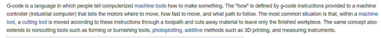
New week, same hard work! This time we all started (both groups) with an introductive lesson with the help of Pietro Rustici, who explained us the main things about the GRBL and G-CODE. After that, we came back to work into our two groups and I decided to study a bit more by myself looking for some definition as the following one:
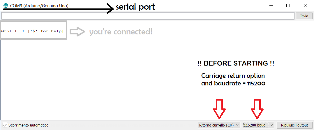
After having read some research material, I started working. But...before starting we all had to know which kind of tools we're going to use. This week, my mates and I will use an ARDUINO UNO board with a CNC shield and four DRIVERS. In order to interpret our GCODE we are going to use GRBL. Before sending the commands I set the required values on the Arduino IDE: Carriage return option and baud rate value at 115200.
So, let's start!
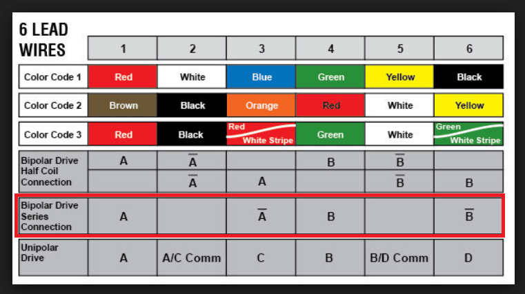
Grbl v0.Xx ['$' for help]. This means all is good! You're connected! :)Obviously, you have to connect the four connectors from the motor to the CNC shield. The needed wires are blue, red, green and black. Their connection is well explained by the following picture. After having done it, you can follow the steps I mentioned before and connect the Arduino board and the CNC shield.
G-Code commands
Now...how works the G-Code? I found this step-by-step guide really useful, and it sum up the commands and the essential things very well. For example:
G0 command moves the machine at maximum travel speed to whatever coordinates follow G0. The machine will move in a coordinated fashion, and both axes complete their travel at the same time.G1 command is similar to the previous one but tells the machine to move at a specified rate called feed rate (F)G2 command is related to the clockwise motionG3 command specifies the counterclockwise motion between two pointsG20 and G20 commands determine the G-Code units: inches or millimeters (G20= inches / G21= millimeters)G28 command is the same writtes as X0, Y0, Z0. It means that the command sends the machine to its home positionG90 and G91 commands are respectively the absolute mode and the incremental mode. The first one causes units to be interpreted as absolute cordinates. The second one, will move the machine the specified number of units from its current point
CNC shield & Arduino
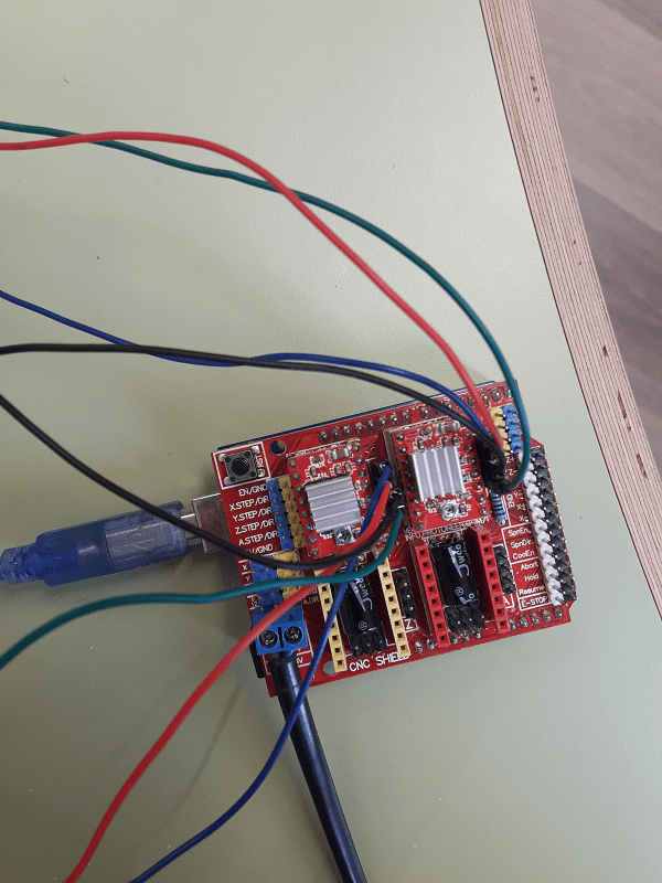
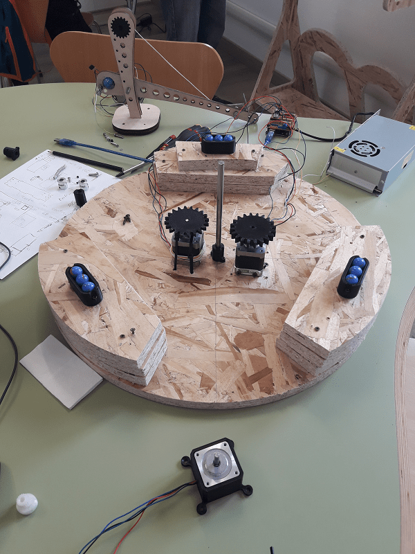
I started trying my rotating base only, without the other two axes on its surface. I only did that test because the axis I did, it would have been represented the support for my mates elements. To sum up, I linked the four wires (blue, red, green and black) on the CNC shield and I did a quick test using the G-Code sender. I just set G1 X10 Y10 F20. The test worked correctly, but obviously I had to edit it in order to calibrate the speed and the degrees related to the plate's rotation. During the first test, our rotating plate did a complete revolution and considering our NEMA17 stepper motor, it means = 200 steps per revolution. After the test I mentioned before, I thought it was time to put the other axes on the machine surface. Only with them we would have been able to understand how the machine would have been worked properly. My mates fortunately agreed with me and Pino had immediately put the lever on the rotating plate's surface. We did a second test together in order to add his axis on the CNC shield. X10 and Y10 were too much because his stepper motor's connection was under the plate (on the OSB basis) and around my rotatory shaft. In other words, it means that the platform wouldn't have turn 360 desgrees and that's the reason why I quickly calculated that 180 degrees were enough. In this way, the connectors wouldn't have been rolled up to the shaft and all would have worked tidily. This means that ...our code will contain a movement related to X+/- and Y+/- dependently on the reached position. Below, you can find some pictures about my first tries: CNC shield and 4 wires connectors and the first test with the rotating plate and the catapult's lever on its surface.
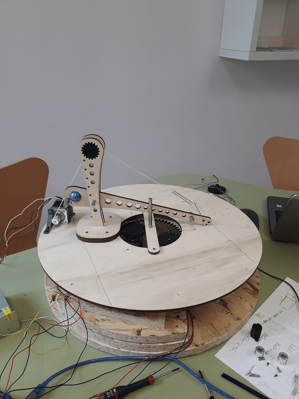
Everything was working correctly, so we obviously added the last axis on our rotating plate. After that, we tried to synchronize all the movements in only one code. As for me, my code will be related to the base support and as I said few lines above, it will be related to a circular movement of 180 degrees. Anyway, we work together in order to synchronize all the axes in the best way. Before doing this, I tried moving only the rotating plate via G-Code Sender. I gave different parameters each time and only at the end I respected the thing I explained before: the rotating plate will do half revolution (180 degrees) because a question of other axes' wires. Only doing this, we can avoid to roll up the others connectors. Here, you can find a short video in which we typed a command in terms of speed and rotation on the G-Code Sender.
After that, we tried to move the plate only to do a half rotation (I explained why in the paragraph above) and then, we added the other axes to see how much weight could be supported by my rotating base. Referring only to some tries, the commands we used to test speed and rotation were the following one. Honestly, we changed them many times in order to find the most appropriate solution. So, the code below just shows what we typed to do aur attemps and to understand which elements worked as we wanted.
Conclusion
We worked really hard during these two weeks, but we had our little satisfactions. I'm still thinking our machine can be better improved and I mentioned some things referred to my own contribution in my mechanical design webpage (future developments paragraph). More than this, you can watch the final result in our group webpage clicking on the video at the top of the page. Last but not least, please take a look to our interface too.
Useful links:
Stepper motor & Arduino (!! Include Stepper Library !!)GRBL Wiki
GRBL v1.1 interface
Universal G-Code Sender (UGS)
How to read a G-Code
G-Code programming for beginners
Download:
All files related to my individual contribution are available in the mechanical design webpage.
During this week, we all worked together to generate our final G-Code (you can find some attempts and tests we did)
