WEEK 09 - Embedded Programming
Antonio Garosi, Eleonora Piccinelli, Dario Bernabini, Tommaso Lombardi, Giada Allocca, Giuseppe Allocca
Index
NodeMCU Amica
www.nodemcu.comDocumentation
Brief description:
This board, based on the ESP8266 microcontroller is a used a simple and realiable connection shield for IoT devices with the use of LUA as scripting language.
This board enables the control over a wide variety of devices (anything with a peripheral among UART, GPIO, I2C, I2S, SDIO, PWM, ADC and SPI standards) with the ease and robustness of an high-level coding.
The microcontroller itself is very powerful, with a 160 Mhz CPU a 8 Mb of flash memory, and it's well documented in the official webiste and benefits from the support of a wide community.
Blinking an LED:
The board as a built-in LED that can be easily turned on and off with few lines of code loaded with the Arduino IDE, such as the following:
						#define BUILTIN_LED 5


						void setup() {

							pinMode(BUILTIN_LED, OUTPUT);
						}


						void loop() {

							digitalWrite(BUILTIN_LED, LOW); //NodeMCU controller works contrarily to many other controllers, so LOW means that the LED is on and HIGH that it is off

							delay(1000);

							digitalWrite(BUILTIN_LED, HIGH);

							delay(1000);
						}
NodeMCU also features programs writte in LUA, which is a versatile scripting language but it's a bit of an overkill for a trivial task such as this.
Final consideration:
Before doing anything, setting up NodeMCU board is not the most simple task. First, you have to download a full set of drivers, then building a firmware, flashing it, and only later you can use start uploading your code (this whole process can be seen in the official documentation). Furthermore, since I don't boast the most updated pc and os, I had to figure out on many instances which were the proper versions to install of the aforementioned drivers (driving me insane for apparently no reason for several hours), but this was not properly disclosed anywhere.
In brief, this board can be pretty useful and versatile, but you have to slog your way to make it work first!
----------------------------------------------------------------------------------------------------
Official site LINK
Datasheet
UDOO Neo has a NXP® i.MX 6SoloX applications processor (Link Datasheet) and embedded:Brief description
Our is the Extended version of the UDOO Neo board. Basically it offers these specs:
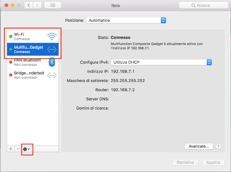
It gives the possibility to be used like a normal Arduino board and to be programmed via Arduino IDE. But, unlike the Arduino, it requires an OS flashed inside a microSD card, in particular UDOObuntu2, a particular Ubuntu distro modified for this board family. The software is available in the Download Page. UDOO Neo is also compabile with Android 6.0.1 Marshmallow, so it can be used for different aims.
Inside the Documentation Page we found all tutorials and files we needed to setting up our UDOO Neo and to start programming it.
STEPS TO PROGRAM UDOO NEO VIA ARDUINO IDE

Blinking an LED
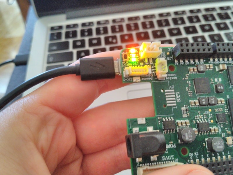
First of all we made a research about LEDs integrated in the board at This Page of UDOO's documentation. We decided to blink the orange LED, connected to Arduino pin n° 13.
int LED_BUILTIN = 13;

void setup() {
pinMode(LED_BUILTIN, OUTPUT);
}

void loop() {
digitalWrite(LED_BUILTIN, HIGH);
delay(2000);
digitalWrite(LED_BUILTIN, LOW);
delay(1000);
}

Final consideration
UDOO Neo seems to be a very powerful board. I appreciated that it can contain an OS and it can therefore be programmed regardless of the presence of a computer. On the contrary, however, I did not like the obligation to install one: I would have liked to be able to use it directly as a simple board.
Official site:
Adafruit Feather M0 Express (designed for CircuitPython)Datasheet
Click here to read the datasheet!Brief description:
Feather M0 Express works with Python circuit, but it can be used also with Arduino IDE. This happens because the Feather M0's heart is an ATSAMD21G18 ARM Cortex M0+ processor, clocked at 48 MHz and at 3.3V logic, the same one used in the new Arduino Zero. The main difference is only in terms of storage. This kind of board uses the extra spaces left over to add 2 MB SPI Flash (that works as storage). When you use Python, the 2 MB acts to a storage for files, libraries and scripts. On the contrary, when you use Arduino, you may know it writes/reads files as a datalogger.
Blinking an LED:
Considering the fact we have just used Arduino individually, we decided to use a different programming language: Python. So, we quickly looked at it, following the needed steps to switch on the LED. If you want to do the same thing, click here to see all the needed passages. In addition, after having done the download, we looked for the micro usb cable. Once have done the connection, the RGB LED starts working. In addition, don't worry if you see a little red led near the USB port: that's ok! Anyway, you have to do a double-click on the black button and doing so, you RESET the board before starting. We tried two times, because during the first test, the RGB LED became red. So, we tried again (maybe it depends on the speed you click the button. We probably pressed it in the correct way the second time and the RGB LED became green! Thanks to this kind of action, the laptop recognize the board and opens a folder named Featherboot. At this point, you can drag your download inside the opened folder. Don't panic if you don't see the folder you've just used, because it will be renamed as CircuitPy. Finally, you will se your green led flashing correctly.
import board
import digitalio
import time

led = digitalio.DigitalInOut(board.D13)
led.direction = digitalio.Direction.OUTPUT

while True:
led.value = True
time.sleep(0.1)
led.value = False
time.sleep(0.5)
Final consideration:
Getting started with the Adafruit Feather M0 Express was extremely easy. The documentation you find on the official Adafruit website is very helpful and we didn't have difficulties.