WEEK 04 - Computer-Controlled Cutting
Giada Allocca, Antonio Garosi, Tommaso Lombardi, Dario Bernabini, Eleonora Piccinelli, Giuseppe Allocca
Index
Characterize your lasercutter, making test part(s) that vary cutting settings and dimensions
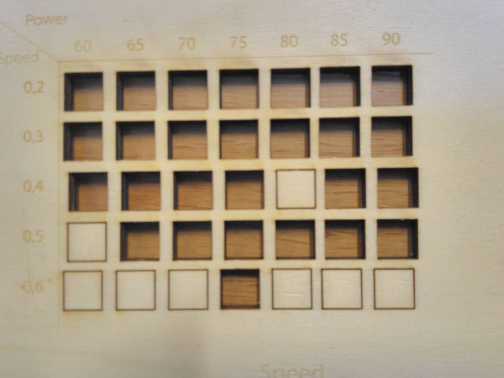
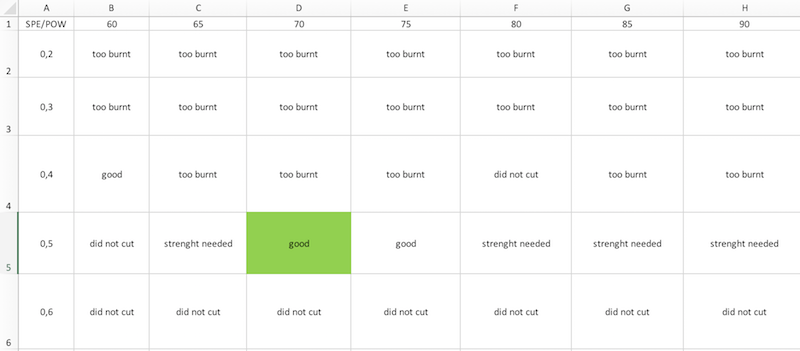
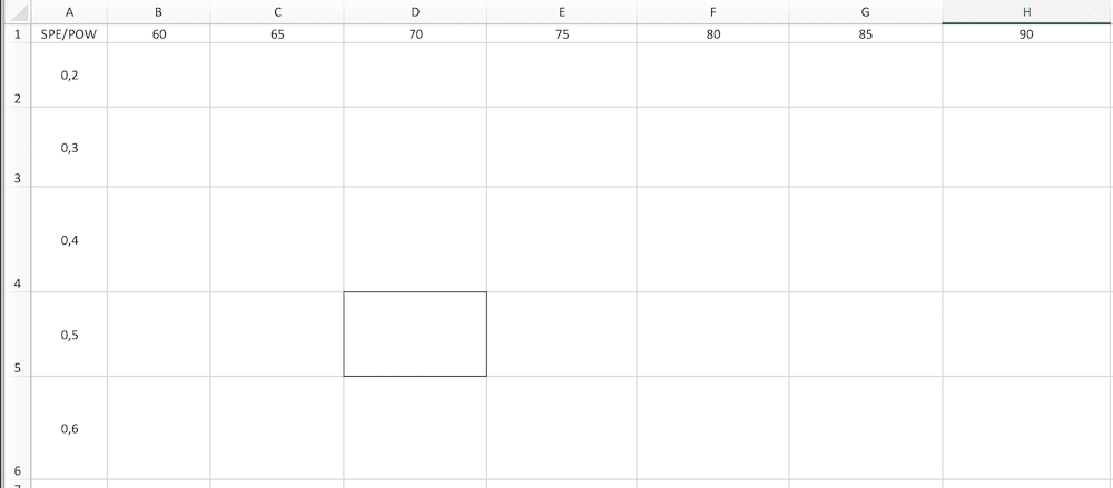
We decided to start with cutting function. We prepare an Excel sheet on which we have created a table containing the power and speed values. We have taken a look at the 2017 documentation of our Fab Lab (Here the Link) and we decided to start from these values:
Power: 60, 65, 70, 75, 80, 85, 90 W
Speed: 0.2, 0.3, 0.4, 0.5, 0.6 %
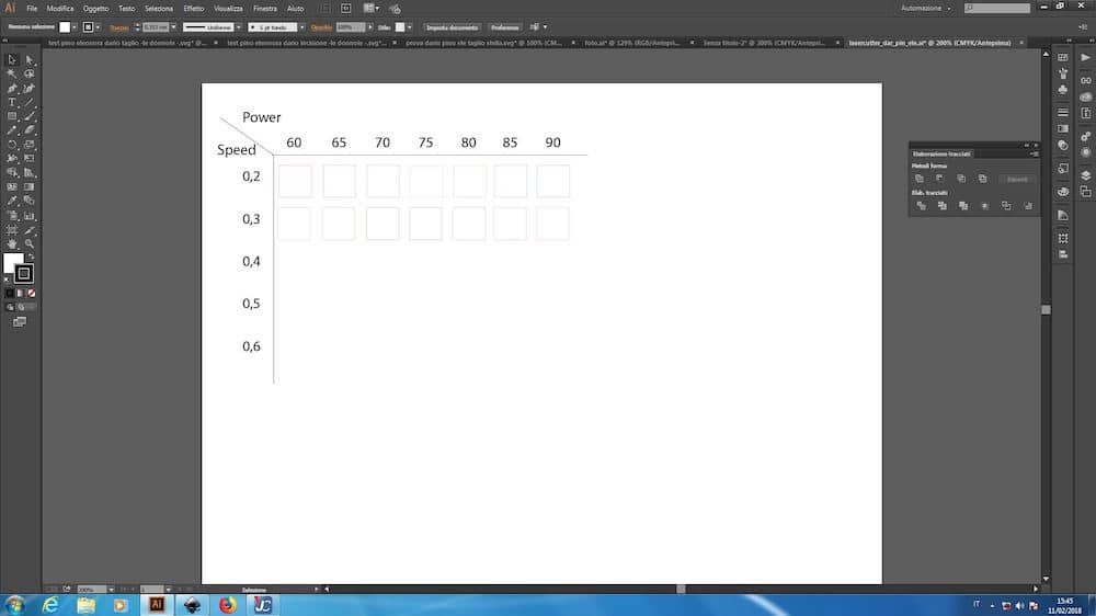
So we created a similar table on Adobe Illustrator. For this table we set lines and fonts completely black (RGB 0 0 0) (we will explain better this parameter during next paragraphs). For every values combination we created a 10 x 10 mm square with a 0.001 mm line (the standard for cutting). We had in total 35 squares. We know that our software for cutting (Trotec JobControl X) supports up to a maximum of 16 RGB colours at a time, which can be assigned different values for cutting or engraving to each of them. The color palette is available in the table below:
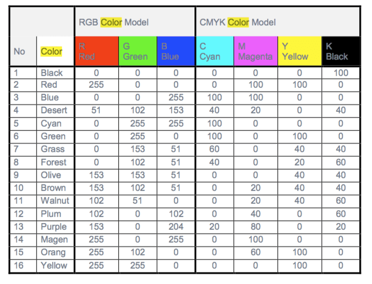
In our lab It was agreed that black was intended for engraving, red for cutting and all the others to be chosen on the basis of the individual projects. For this reason we began colouring the Illustrator squares in red, for a total of 15 colours per cut. Here an example:
If you want download our SVG file and use it you can download it from squares_test.ai (651 KB). You have only to change colours and remove/add what you want.

So we created a similar table on Adobe Illustrator. For this table we set lines and fonts completely black (RGB 0 0 0) (we will explain better this parameter during next paragraphs). For every values combination we created a 10 x 10 mm square with a 0.001 mm line (the standard for cutting). We had in total 35 squares. We know that our software for cutting (Trotec JobControl X) supports up to a maximum of 16 RGB colours at a time, which can be assigned different values for cutting or engraving to each of them. The color palette is available in the table below:

In our lab It was agreed that black was intended for engraving, red for cutting and all the others to be chosen on the basis of the individual projects. For this reason we began colouring the Illustrator squares in red, for a total of 15 colours per cut. Here an example:

If you want download our SVG file and use it you can download it from squares_test.ai (651 KB). You have only to change colours and remove/add what you want.
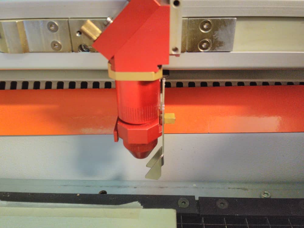
At the same time we power on the laser cutter machine. Supervised by our instructor Matteo Sirizzotti we inserted a plywood sheet inside it and using the command panel we place the laser pointer at the desired point and begin to raise the surface. We focused the laser using the special tool provided. The machine is calibrated when the small tool falls from its position when the table is raised. And than the machine is ready for any operation.

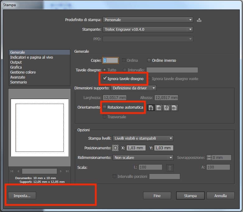
On Adobe Illustrator we clicked on File - Print. Here start the settings about cut parameters:
put the tick on "Ignore Artboards"
remove the tick on "Auto-Rotate"
Than click on "Setup".
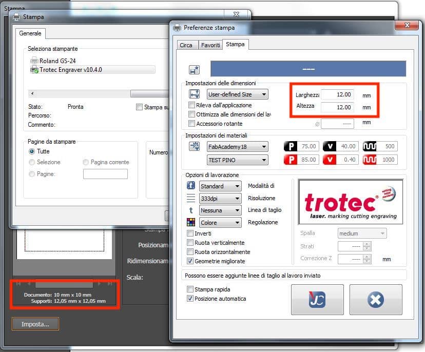
In other pop-up menu, we clicked on "Preferences". Here we set up measures for our document. In the example below the original project was 10 x 10 mm and here we put 12 x 12 mm, adding just 2 mm of tolerance. We left the other parameters unchanged.
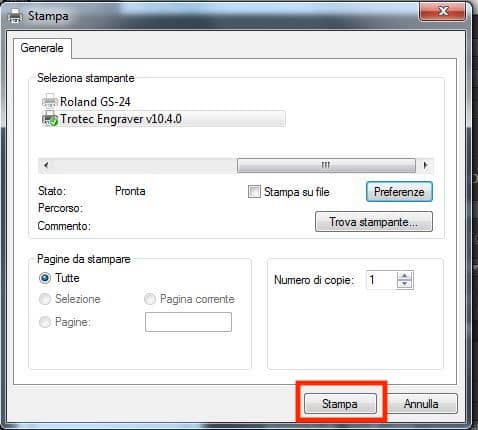
We confirm these parameters. In the previous menu we clicked on "Print". We don't know why, but there is a sort of bug for which we must press "Setup - Print" for a second time before pressing "Print" from the Illustrator menu.
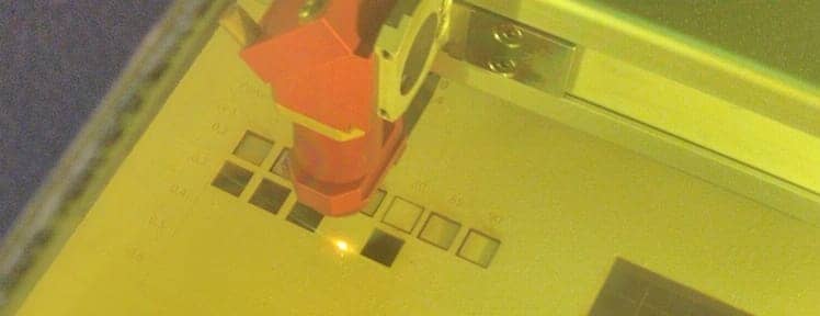
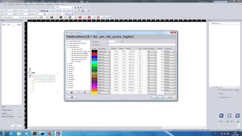
Screenshots represents three cuts made to complete the grid.
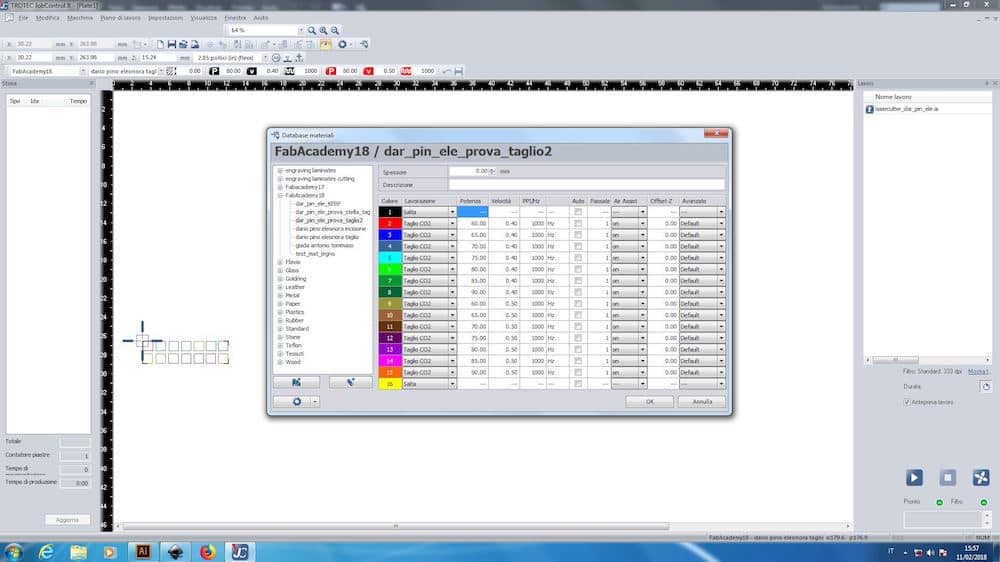
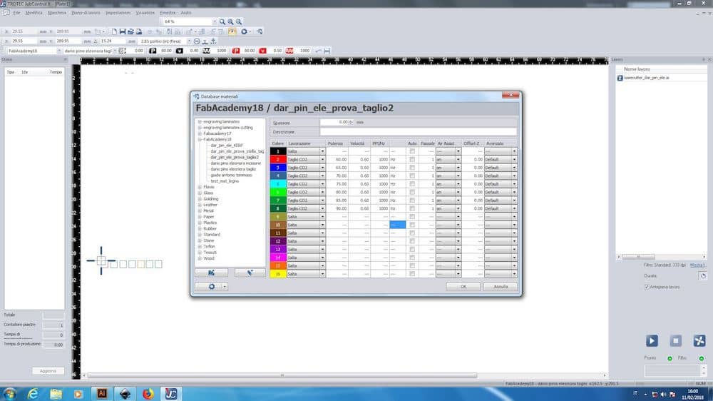

In other pop-up menu, we clicked on "Preferences". Here we set up measures for our document. In the example below the original project was 10 x 10 mm and here we put 12 x 12 mm, adding just 2 mm of tolerance. We left the other parameters unchanged.

We confirm these parameters. In the previous menu we clicked on "Print". We don't know why, but there is a sort of bug for which we must press "Setup - Print" for a second time before pressing "Print" from the Illustrator menu.

Screenshots represents three cuts made to complete the grid.


We made the same things for printmarking. We prepare a table and we test:
Power: 60, 65, 70, 75 W
Speed: 35, 40, 45, 50 %
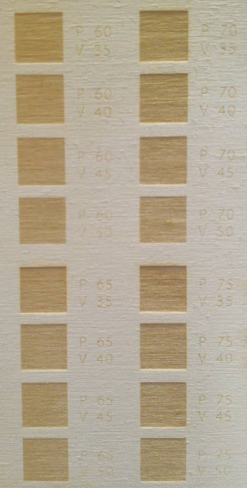

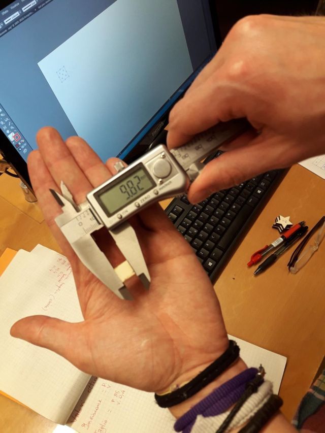
After some cutting, we measure every little square with a digital caliper in order to find the kerf and note it on a paper sheet. The best result we found is available in the following paragtaph.
