
|
|---|
Assignment |
Final Project |
About Me |
|---|
Week 5
Assignment
The challenge this week was to make single-sided pcb and solder parts using a milling machine.
That link is a group assignment page that contains an explanation of PCB and milling machine.
Group assignment link
Milling machine
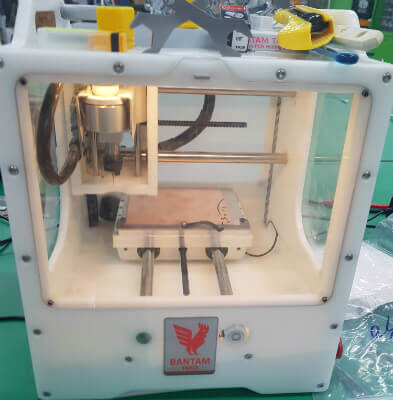
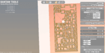
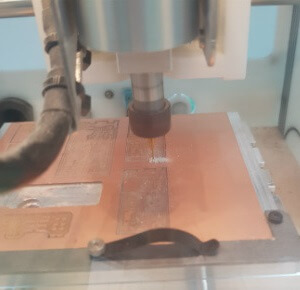
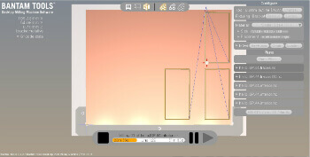
The millingmachine used in the Seoul innovation fablab is othermill,
but it has recently been changed to bantam, but it is still called othermill.
This week, I decided to try milling with this.
Milling
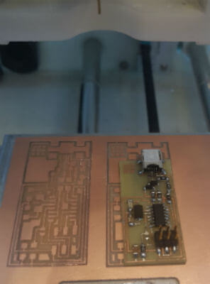
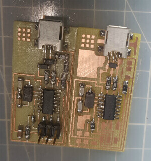
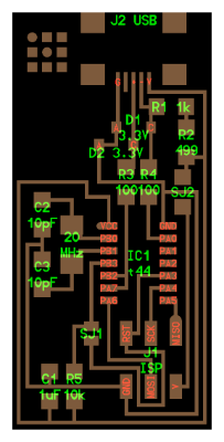 Part location | 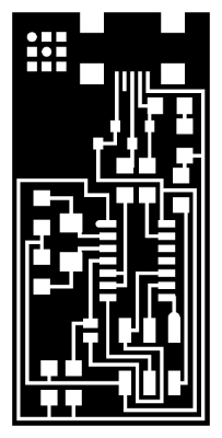 Bitmap | 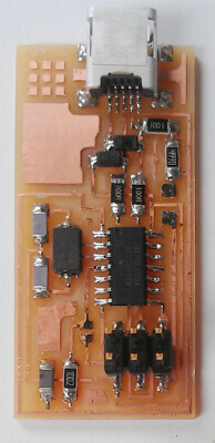 Finished product |
|---|
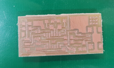
The PCB I made is Hello.ISP.44.
My final project was chargeable silent wood mouse, so I chose this version to practice attaching the usb connector.
The ATTiny44's legs are thin and many, so you should be careful when you look at the finished product.
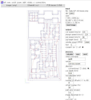
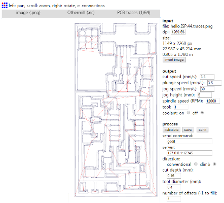
I uploaded the bitmap downloaded from the fab archive to fabmodules.org
according to the othermill specification and downloaded it with the nc extension name.
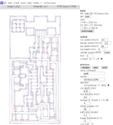
The setting value in the fab module is cutspeed: 2.4 plungespeed: 2.4 jogspeed: 5 jogheight: 30 RPM: 12000.
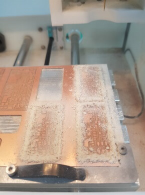
I opened the converted nc file with othermill and started to cut it on the copperboard.
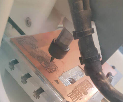
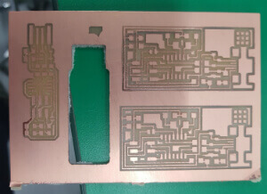
I shaved two things and it seemed to come out well. But there was a problem.
It was a PCB with a dpi of 1000, but I did not recognize it, so I made it bigger than it was.
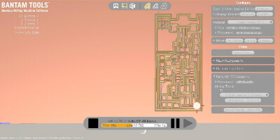
So I created the nc file again and opened it through othermill.
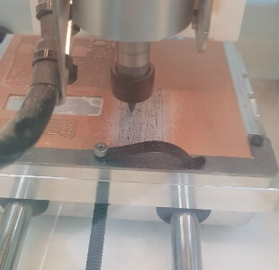
After that, I milled out 2 times and the second one appeared to be a little better,
so I pulled outline with cutter, and decided to take it off.
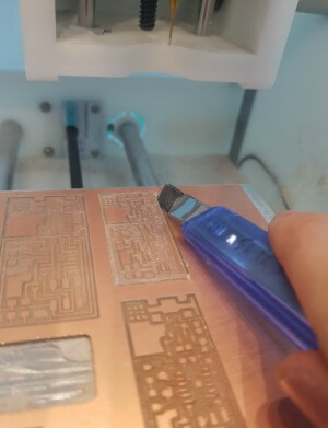
The attempt to remove it was good, but unfortunately,
the copper plate broke down a little, and unfortunately it could not be used.
It seems to work well when you take off the copperboard and think that you lift it slowly rather than hastily.
But I couldn't do it and it broke.
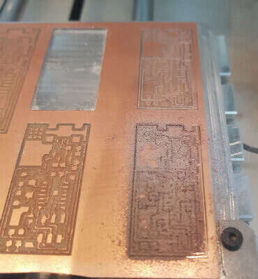
setting value: cutspeed:3.5 plungespeed:3.5 jogspeed:30 jogheight:5(mm) RPM:12000
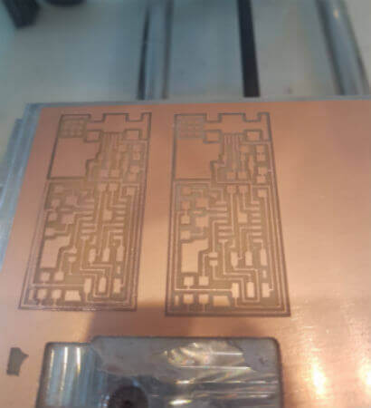
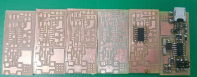
The two right sides were shaved according to the setting of Seunghwan Ji taking classes together.
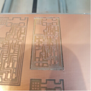
After that, I removed the remaining 3 PCBs and removed them well this time.
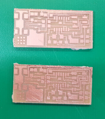
However, I do not know what was the problem this time,
but one or two of them caused a problem according to the setting value of Seunghwan Ji.
The rest of them were very well milled, and the instructor was impressed.
I trimmed it with sandpaper, cleaned with soapy water it and prepared to solder it.
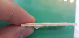
I made 8 pcbs(Incorrectly milled) with one copperboard, so I got a chance to change the copperboard.
I slowly lifted up the PCB as if it had been removed, but I broke the half and only this is left.
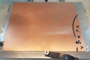
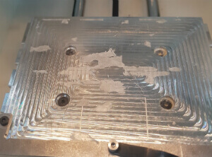
I then affixed a double-sided tape to the back of the copperboard, then trimmed it and pasted it onto the othermill sacrifice board.
(That mark has been marked as not to be used because of the step on the back when cutting the copperboard.s)
Soldering
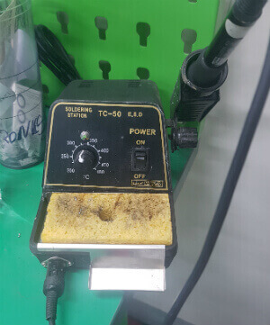
The iron used in the Seoul innovation fablab is TC-50.
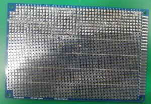
I practiced soldering using the universal board provided by the instructor.
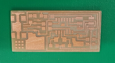
Then there was a problem in soldering the milled pcb.
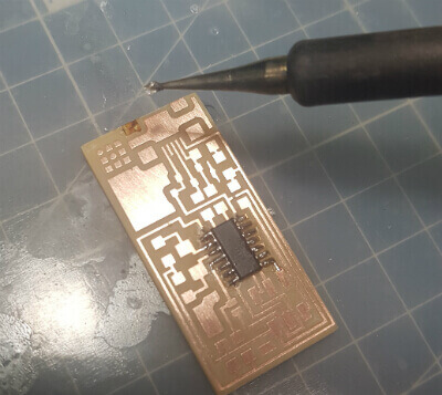
I left it on the copperboard for too long and the copper fell off.
Even ATTiny44's polarity was reversed, and it tried to pull it off, but failed.
(You can see that the wire section on the lower right has fallen.)
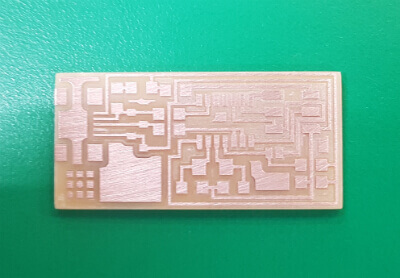
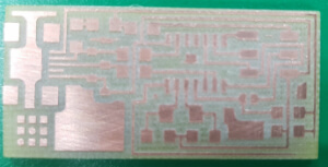
So again, I milled the PCB again, but this time,
the circuit that gave the sandpaper a lot of power was taken away and milled the 8th PCB.
I did not know how to adjust the polarity of the diode during soldering and I asked the instructor.
The diode refers to the + portion as A (Anode) and the - portion as C (Cathode).

Source:https://luguang.en.alibaba.com/product/60699633419-209394707/0_2W_3_3V_SMD_SWITCHING_ZENER_DIODE_SOD_323_MM3Z3V3.html
The instructor showed his PCB and looked at the top of the diode.
On the upper side of the diode, there is a small solid line and the solid line part is C.
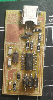
And this is my finished product.
When soldering, the parts were so small that it was hard,
and it was very hard to make the round with the lead shining and it was very difficult
in that the parts could not be properly positioned even if the hand was shaken a little.
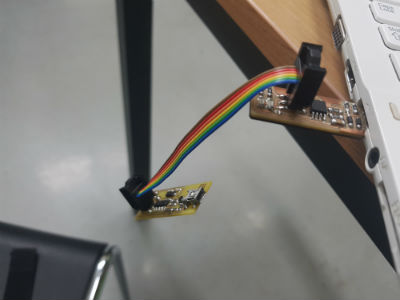
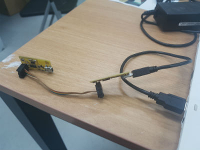
ISP programming
I borrowed an ISP from an instructor and followed programming as described on this page.
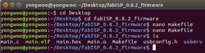
Change the directory according to the path where the firmware is located,
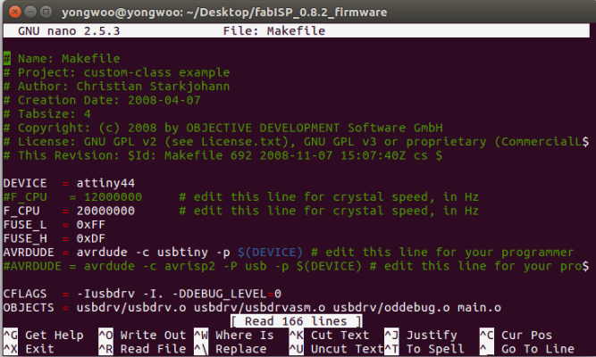
I am ready to program by modifying the Makefile.
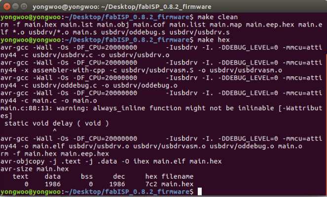
But there was a problem.
make clean, make hex worked fine, an error has occurred since make fuse.
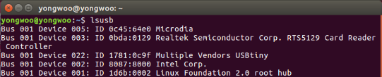
I got advice from the instructor and checked the shot using a multimeter.
However, there was nothing wrong, but I found the problem too naively.
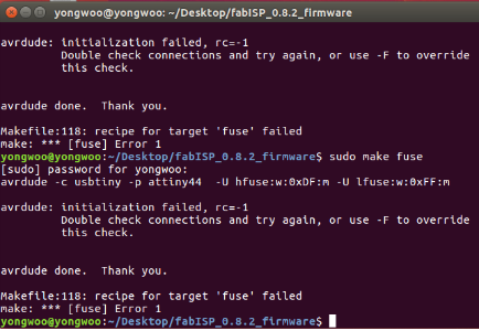
I was trying to program with an ISP created using ATtiny45, so I got an error.
So I programmed it with an ISP made using ATtiny44,
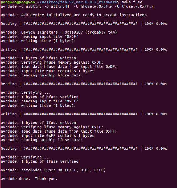
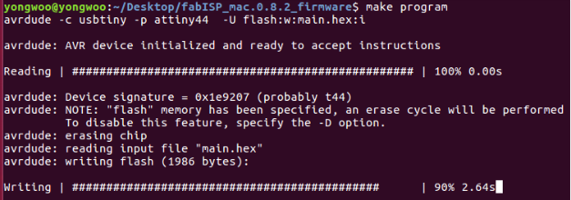
and it worked fine with no errors!
You can download my work here
zip file download