WEEK 9 - MOLDING AND CASTING
Assignment
individual assignment :
design a 3D mold around the stock and tooling that you'll be using,
machine it, and use it to cast parts
group assignment :
review the safety data sheets for each of your molding and casting materials,
then make and compare test casts with each of them
Here is the link to Group assignment.
SCANNING
I tried to scan my head and cast it. I put my camera on tripod. And I sat on the rotating chair. I rotated step by step and took pictures with remote controller. I divided processes to 4 rounds in different angle. First round was eye level, and once was lower than eye level, other twices were higher than eye level. I took 88 pictures in every different angles.

I opened Autodesk Recap and open those pictures. And start Photos to 3D. After a long time, uploading sources, processing create the mesh… output was not good. Upper part of face was fine but else parts were terrible. I thought it’s because object changed while repeating get up and sit about hair and wrinkles on clothes.
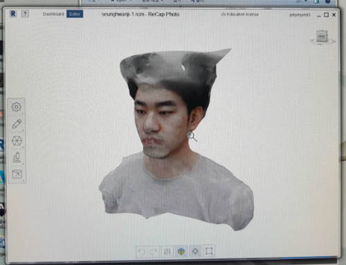
After I trimmed my hair, I repeated same process. I took 76 pictures and created 3D file. Output was better than first trial, but it was not good too. Left side of head was fine but other side wasn’t created. And it was impossible to mirror the left side. I tried twice but results were same as before.

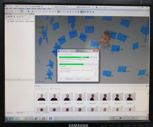
I asked to instructor and he recommended other program named Photoscan from Algisoft. It provided 30 days free trial with full function. I downloaded program and followed the tutorial video. I uploaded same 76 pictures and put align photos button. It showed me a 3d head and there were 76 flag which were the point of taking picture. Then, I created cloud dense and mesh. I can check shade view and solid view. But it was not enough to 3d milling. It was too rough.
MILLING
Tiny CNC, Asphire
MACHINE
MATERIAL
Chemical wood
Chemical wood is similar to wood, but it has no grain. its artificial material. It’s really easy to manufacture and quality is fine. It’s color is light pink. And 51mm thick. I cut chemical wood to two part and work left and right sides each. Those two parts have not exactly same sizes so I decided to set origin point on center. I drew two diagonals and the intersection point is center. I put tip pointed drill bit and move the tool to center manually. And set the origin point.
ASPHIRE
I tried to cut right side first. I opened the program and set the material size. 102*94 and 50mm thick.
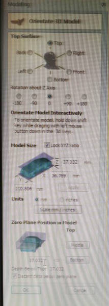
I imported 3d file of right side of mouse. And rotate 45 degree to get inside the material. And I needed to make something to grip both molds on exact location. On the vacant area I created two cylinders. It was important to make sure the location of those parts two make on both side. One was (30, 30) and other was on opposite side. Processes were rough cut with end mill, finish cut with ball-nose, profile cut with end mill again.
ROUGH CUT

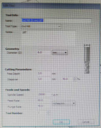
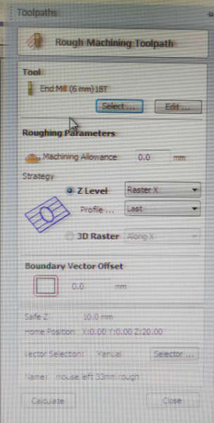
If I create the rough cut path the program automatically calculate the 3d shape and create the paths with certain distance. I used 6mm diameter end mill which has same diameter with shank. And i should cut 35mm deep so I used long end mill. I set cut depth and stopover 3mm.
After I created tool path, I check working process with preview.
Milling
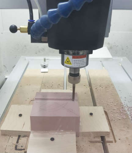
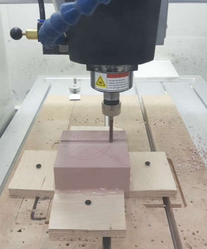
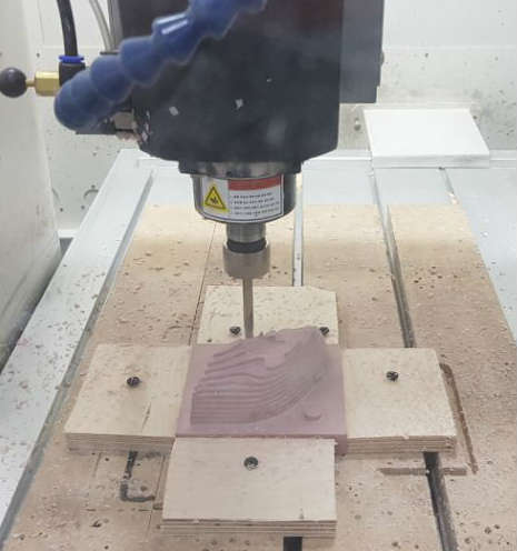
I checked deepest depth was about 35mm, I fastened end mill about 45mm long. On the milling machine program it provided live preview.
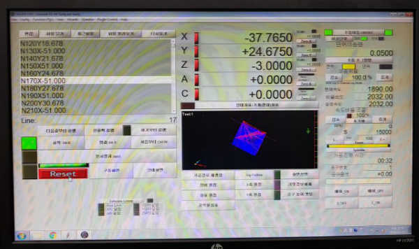
So I could check again and prevent accidents. I started milling, chip load was fine, sound was fine.
FINISH CUT

Most important thing on finishing cut is the quality of surface. So I changed the value of stopover to 10%, 0.6mm.
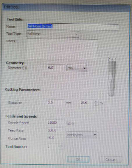
While rough cut was zigzag cut operation, I changed it to spiral cut operation. Because spiral cut will make more smooth surface. I created paths and checked the preview.
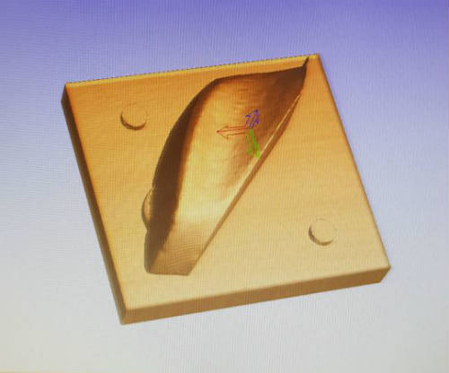
It was fine. I changed the tool to ball-nose and probe the tool length on highest layer.
Milling
Even stopover was 0.6mm, it took short time because it pass one point only once. Output was fine. It even described the bump details on side of mouse. But I remained fillet on bottom part because of the ball nose tip.

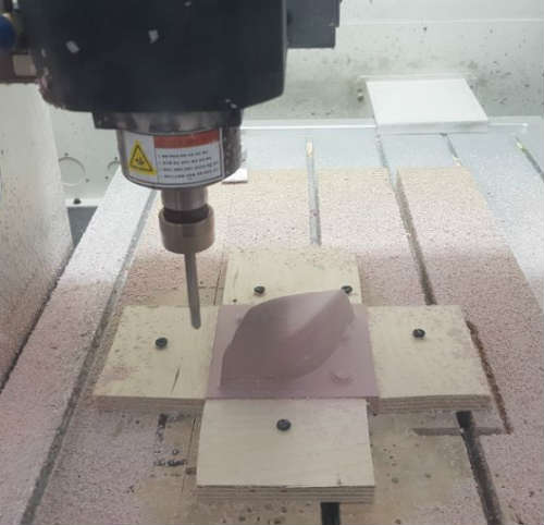
milling progress
PROFILE CUT
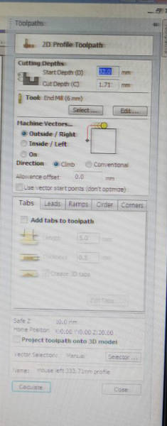
To remove this fillet, I should profile the outline of mouse. Fortunately there was tool to create vector line from 3d. I created the curve. Most important thing of this work was the depth of material. The whole length of right part os mouse was 33.7mm. So I set start depth 32mm and cut depth 1.7mm. And I checked it was outline cut and climb way. After create path, I checked preview.
Milling
To profile I should change the tool to end mill again. But while finishing cut, it removed upper part to measure the tool length. So I put another chemical wood on the bed and check the height with level meter. It was same level and I probed tool length on that. I started milling and I cut deeper than bottom layer slightly. But it was fine to me and it was even better to prevent leaks when casting.
In this process I decided to make the holding part negative because left side of mouse has higher length so it was advantageous to make positive on left side. So I created pocketing tool path inside the circle.
LEFT SIDE
Left side
Same process with right side, but it was mush easier. I drew center point on material and opened the file. I rotated the mouse -45 degree and I created two cylinders on exact location. I created rough, finish and profile cut paths. And checked the previews in turns. Those were fine and I saved the tool paths. And milling was fine too.
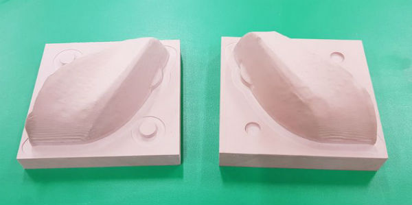
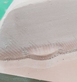
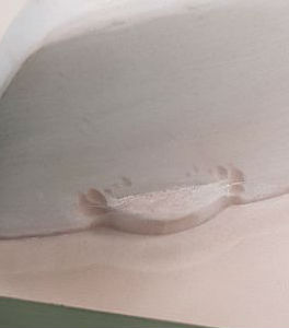
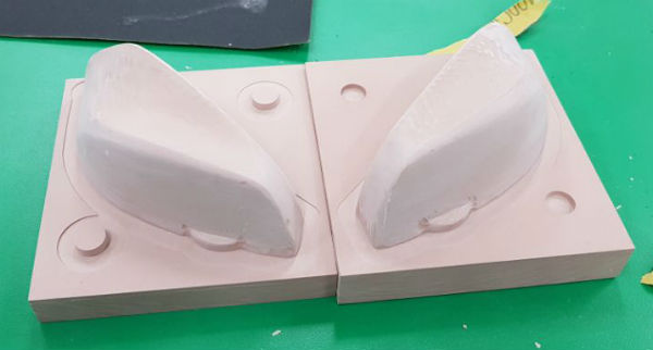
I got two parts of positive mouse. It was smooth on upper side because of finishing cut was spiral direction. But on the slope part It showed rough trace. So I sanded surface with sanding paper. And also I made it sharp on the mouse wheel part with cutting knife.
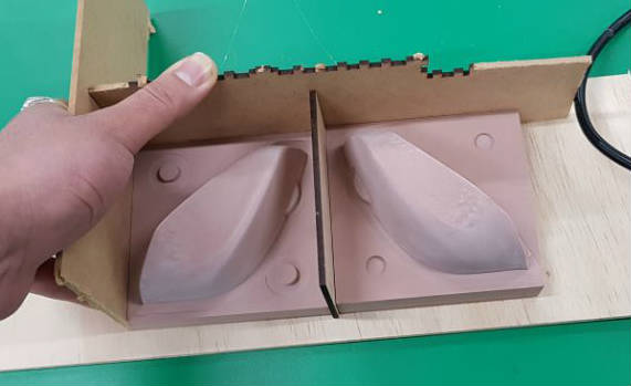
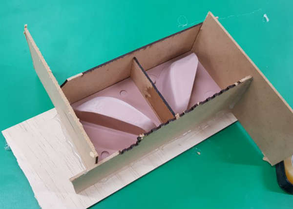
To pour material to make a mold, I needed to surround the edges. I cut MDF sheet to make a wall between two parts and put. Then with 4 MDF sheets I surround every edges. Highest point of mouse was about 50mm, I made the wall 60mm height. And glued every connection part with glue-gun to fix and prevent leak.
MOLDING
Molding
I used Mold star 30 which is silicon from the vender Smooth-On.
It’s pot time was 45 minutes and cure time was 6 hours. It consists of white colored main material and blue colored hardener. They call those part A and B. Mix ratio is 1:1 by volume so it doesn’t need weighing scale. Vacuum degassing is not necessary but it will make better output. It has enough pot time to degassing. I decided to do vacuum degassing.
First I needed to calculate the amount to use. First size was 100*95*50 to cover enough. Volume is 475cm3 and I need double of it. So the amount is 950cm3. But there were two parts of half mouse. It’s about 1/4 volume of box. So I decided to make 700ml, 350ml*2. As mix ratio is 1:1, I poured 350ml of partA and partB in separate cup.
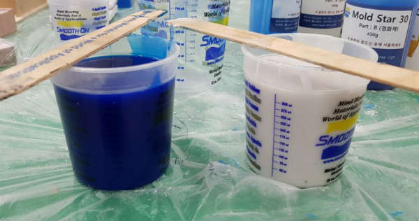
And I poured these two materials in big cup.
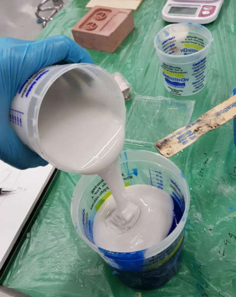
I planned to use 45 minutes pot time, 10mins mixing, 20mins vacuum degassing, 15mins pouring.
After pouring to big cup, I mixed with wood stick 10 minutes being careful to not make bubbles.
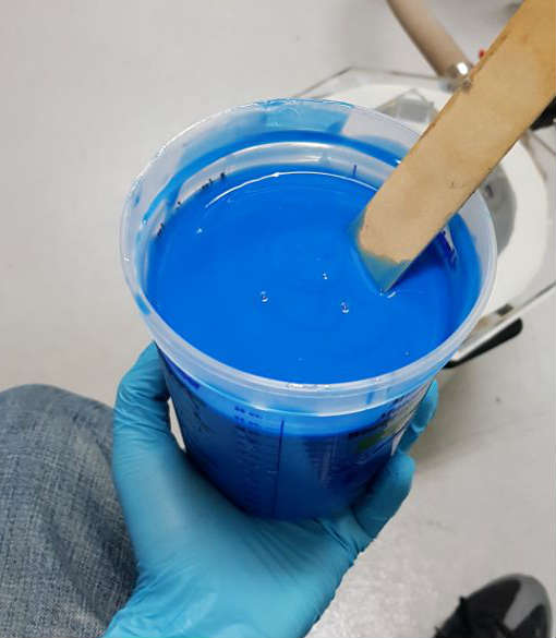
Then, move to vacuum degassed and start degassing. It bulged up immediately and I repeat vacuuming and exhausting.
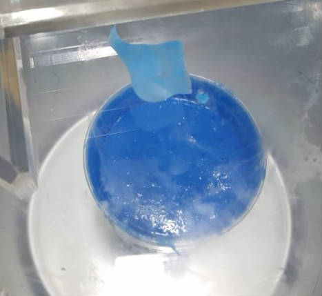
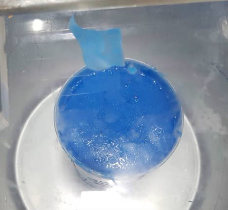
I thought it’s not efficient so I wrapped upper side of cup to make higher. And degassing again. It was much better.
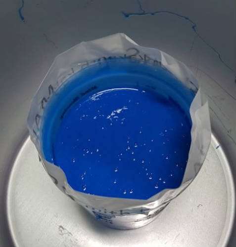
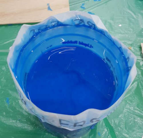
Then I adjusted valve to appropriate pressure and waited. After few minutes, level of bubble went down, so I increased pressure. I degassed 20 minutes.
When pouring, i used wood stick to shed little by little. After silicon covered mouse, I poured to the proper height.
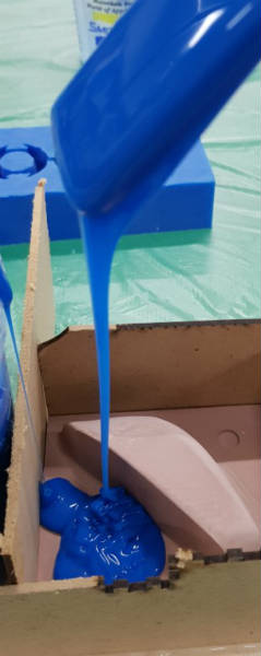
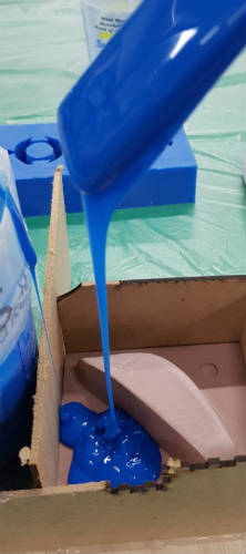
At this point I realized I didn’t spray release agent. But it was too late. Then I sprayed on the second one. After spray, I repeated same work.
After pouring done, I dropped whole work on the table to remove the remaining bubbles. And I covered it with wood sheet to prevent dust.
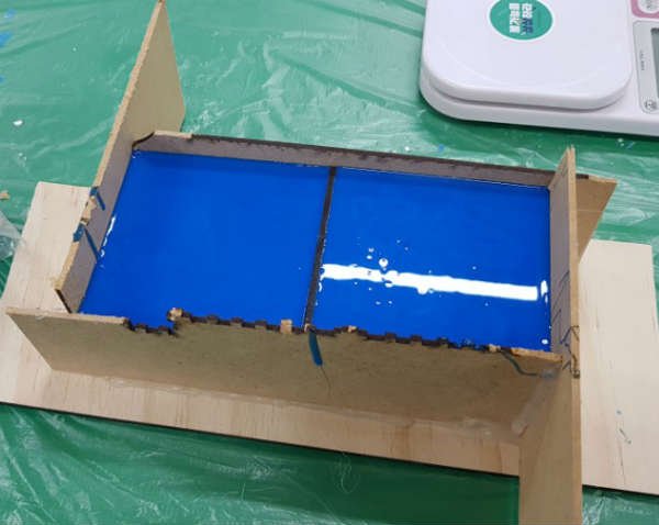
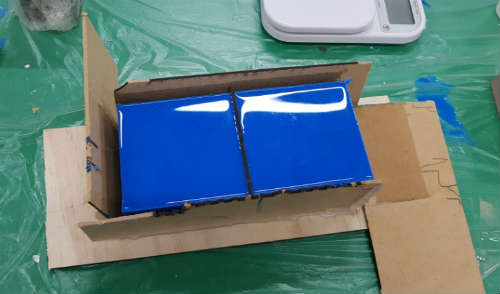
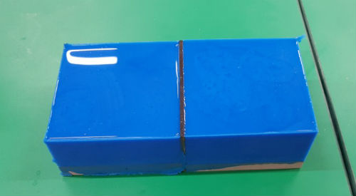
6 hours later, I checked it get hardened enough. It was fine. I removed MDF walls, and separated two parts. Then, I cut the thin part which penetrated to slight gap between chemical wood and MDF with cutting knife. I tried to pilfer chemical wood from silicon. It was easy to put out with release agent, while it was difficult on without release agent. But both part was really good enough to cast.
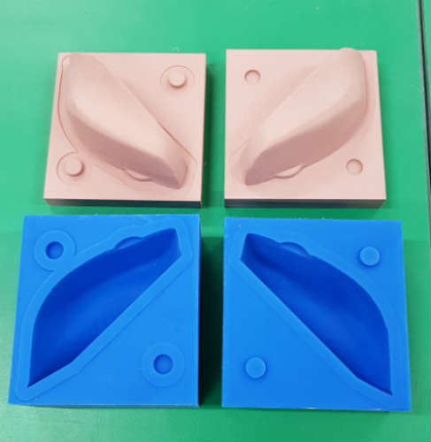
CASTING
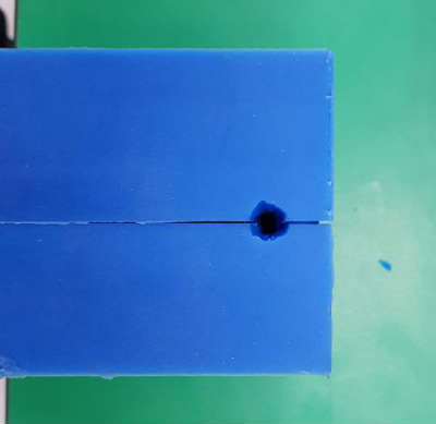
For casting I should make entrance. I decided to make an entrance at the bottom, flat surface that easy to finish. I assembled two parts and marked two points which are going to be diameter of entrance hole. Then I drew cone shape.
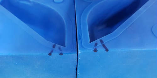
And I cut entrance with the cutting knife. It has cone shape that has large at the outside and small at the inside.
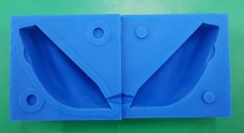
FLEX-FOAM IT-X
My first casting material is FLEX-FOAM IT-X from vender SMOOTH-ON.
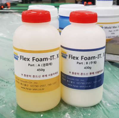
It’s kind of urethane that has expanding and porous characteristic. You can see the specific information here.
It expands 6 times right after mixing. And it has mix ratio by volume 1A:1B. So I measure volume first. I poured water on each mold and poured again in the cup. It was 137ml in total.
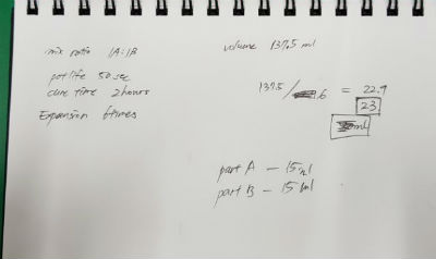
Because flexfoam expands 6times so I divided 137 to 6 that is 23ml. I decided to make 30ml. Because making ample is better to deal with accident and I saw when I give some pressure to mold it became more hard and it’s easier to mix. I pour part A, B on each small cup.
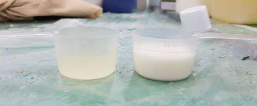
And pour both of material in big cup. It has 50 seconds pot time that make me hurry. Then I mix aggressively with wood stick. Also I pour on one side rather than pouring into entrance hole because it has really quick pot time.
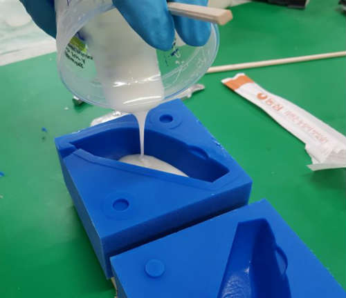
I poured first and cover with the other side mold and clamped.
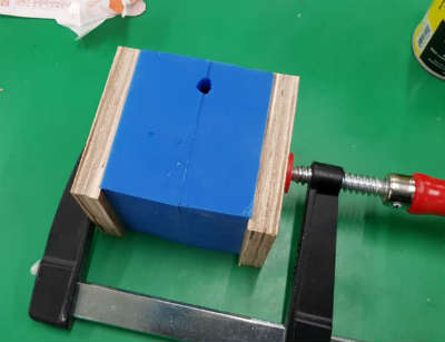
And left it with entrance hole upside. It should be swollen over the entrance but I didn’t. After an hour I unclamped and checked the output. It expanded just half of the mold.
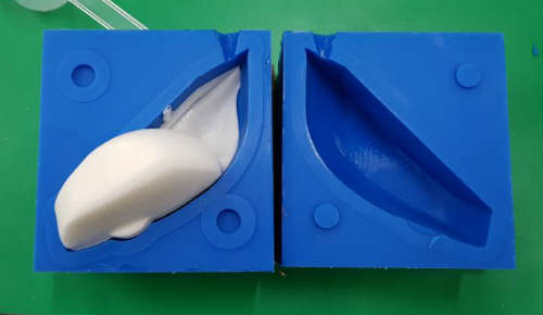
I thought it’s because of the amount is so small to mixed well.
Second trial with FLEX-FOAM
I tried again with some color. I used liquid urethane colorants called SO-STRONG from SMOOTH-ON.Here is the page
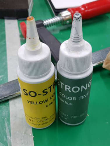
I mixed green and yellow to make light green. First I dropped colorant on partB and mixed perfectly.
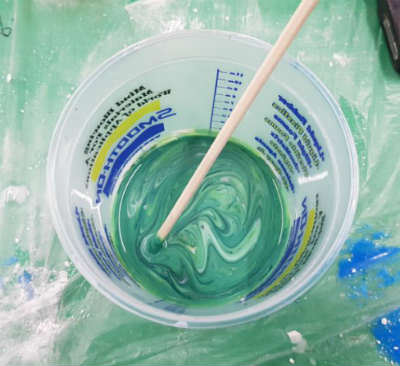
Then pour partA to B.
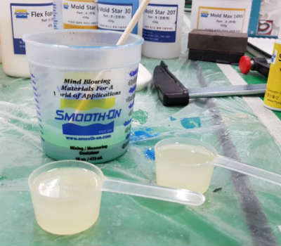
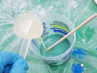
I pour on the one side of mold and assemble with the other side. Then clamped it. I pour plenty to make sure it covers whole mold. But in this case I put too much of urethane so it bulged up so much and it made gap between the molds.
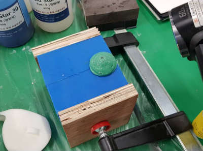
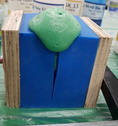
But output was fine.
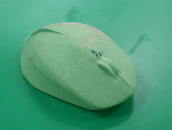
TASK-16
I tried task16 also. It is kind of urethane too. But it doesn’t expand at all. Here is the page of its detail.
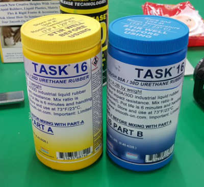
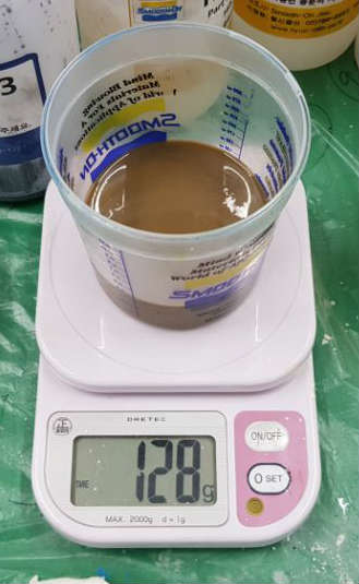
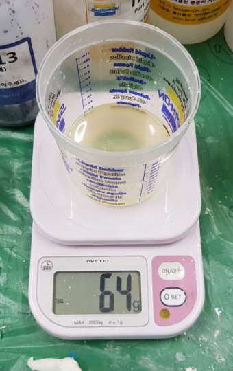
Its mix ratio is by weight 1A:2B. So I divided 150ml to 1:2 that 50ml:100ml. But I poured part A 64g so I decided to make part B 128g total 192g.

It has 6minutes pot life that is too short to vacuum degassing. So I mixed both parts and just pour it to the hole. I clamped both side of molds and poured. But it has high viscosity and hole was too tiny. It just stopped the entrance. So I used wood stick to make hole big. But was inadequate to pour material to the top of the mold.
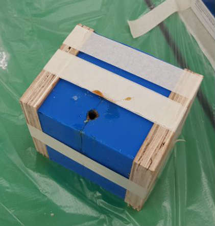
I tried hard but left material in the cup get hard impossible to pour.
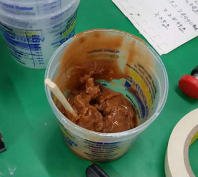
It has 24hours cure time. But after about 3hours, left material in the cup get hard enough. So I opened the molds and there was only half of mouse. I need to make hole bigger and another hole to air get out.
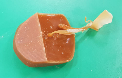
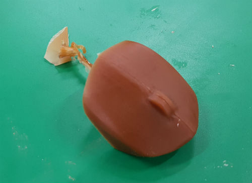
Here are my works.
Download