WEEK 4 - ELECTRONICS-PRODUCTION
Assignment - group assignment:characterize the specifications of your PCB production process
Here is the link to Group assignment.
individual assignment:make an in-circuit programmer by milling the PCB, then optionally trying other processes(ATtiny45)
Milling
First, for making ISP board, download png file from here
There are png files for trace and outline cut.
Then in the fabmodules pagethat makes possible to create file for milling machine program.
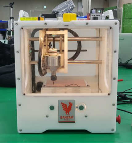
PCB milling machine in our fablab is Bantam tool that was other mill before.
In input format press png and open file to make. In output format choose other mill that use .nc extension.
And I can put various value like tool spec and working values. I put cut and plunge speed 3.5mm/s for trace. And jog speed and height 30mm/s and 5mm. and, cut depth was 0.15mm for just cut copper on board. Offset count is used for how thick you want to cut except line you need. If offset count -1, you can cut every board except the line. I put 3 for offset and 50% for overlap. Then click calculate button to check the path. If there is no problem, click save button to create .nc file.
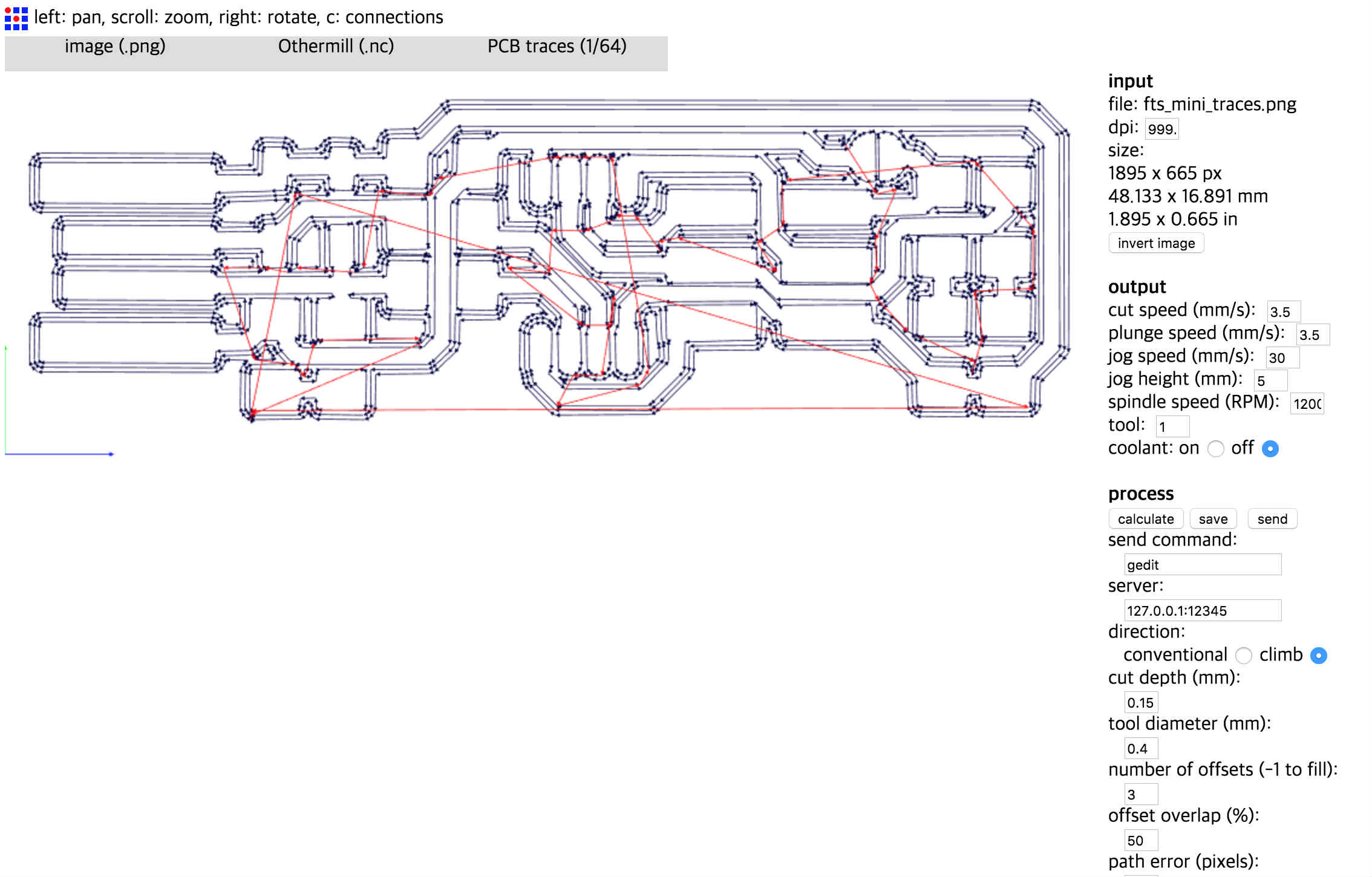
Cut speed is the speed of tool moving while cutting.
Plunge speed is the speed of tool while approaching to material.
Jog speed is the speed of tool moving while off the material so it could be much faster than cut and plunge speed.
Then connect pc to machine.
Material
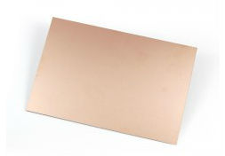
Material is FR1 that has single sided copper and its body is phenolic paper. Its thickness is 1.7mm but it is not that flat perfectly.
First probe the size of board, it was 127*105. And I used double-sided tape to settle tight on the machine board. There might be some gap on the center area if you use clamp to hold the material. Double- sided tape should be attached on all surface of board and there should be not overlapped part that makes little change of thickness. Then place material on the machine at (0,0)point. And put size and thickness of material on program.
Tool
To equip endmill on machine
1. release nut
2. Put collet inside nut that exactly fit to end mill you use. (Before assemble you should clean collet and nut. If there is chips from former work, it may occur some problem with shaft of end mill)
3. Then fasten nut with collet.
4. Put end mill inside the collet (be careful to make sure not to drop end mill. It has tiny cutting bit that is easy to be broken)
5. Fasten nut tight with spanner.
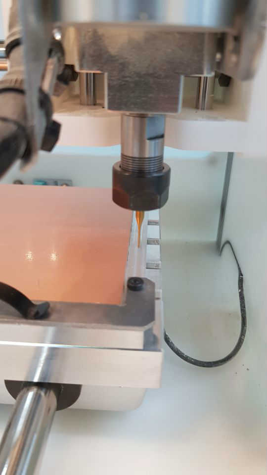
Then I should change the tool on program. Choose 0.4 end mill that instructor saved before.
If tool changed, program automatically start some process to probe tool length. I set the location of end mill on aluminum board not material. Then, endmill slowly going down until it gets to the board. If tool touched the board, electricity goes through and stops.
Trace cut
Then open .nc file and place the file using placement. It was (4.4) I did. And to make the thickness of material thick sure, I should probe the material thickness on bitbreaker menu. I set the location on center of my working area to make it more dedicate. And place the clip to electricity go though the copper surface.
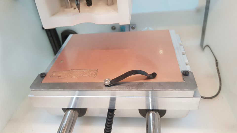
It said thickness is 1,71mm.
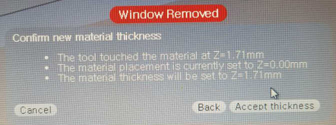
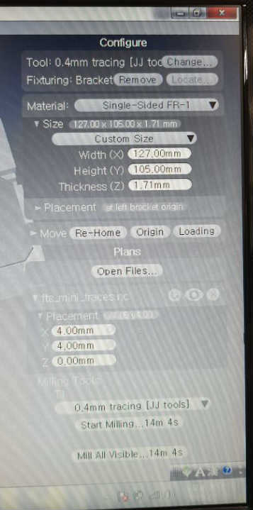
And put that value on thickness.
Then remove clip.
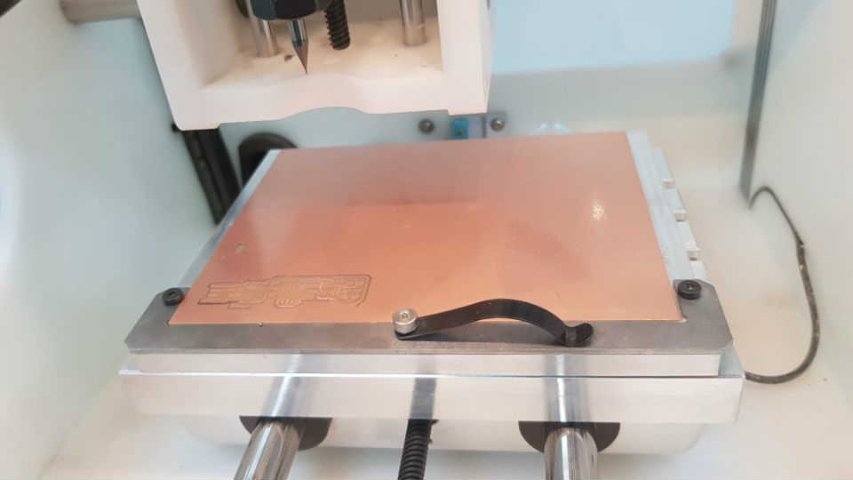
Start milling
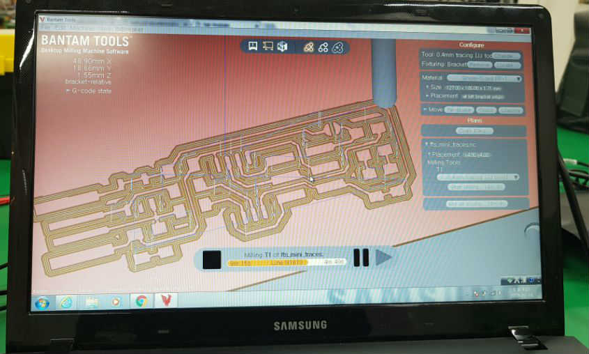
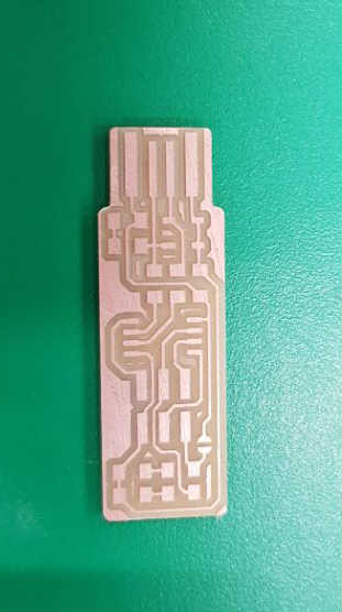
After milling done, open the window and clean chips on the surface. There was some part that didn’t cut on the right, lower part.
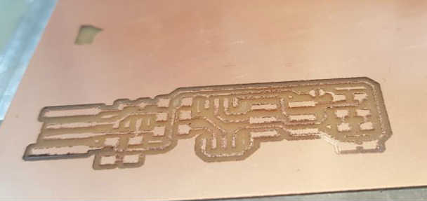
I think it’s because material thickness is not exact. So I did again on the upper side.
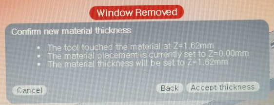
I repeat probing material thickness and it said 1.62mm. It was fine with second work.
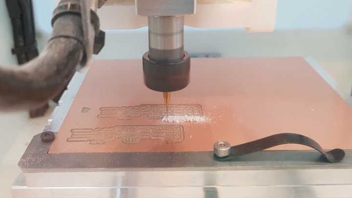
Out line cut
Outline cut
Same process with trace, I put cut and plunge speed 0.4mm/s and jog peed and height 30mm/s and 5mm. And cut depth for 0.6mm and stock thickness 1.65mm. When start milling there is warning about it may invade the aluminum board because material thickness is 1.62mm and working depth is 1.65mm. I push ignore and proceed.
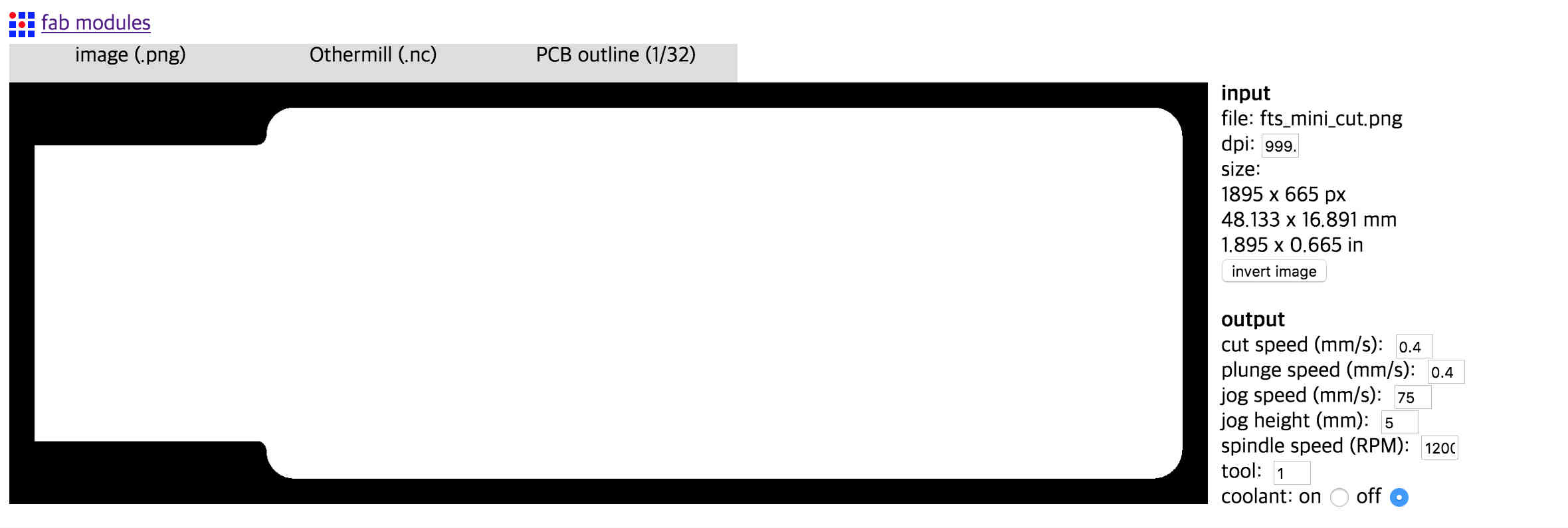
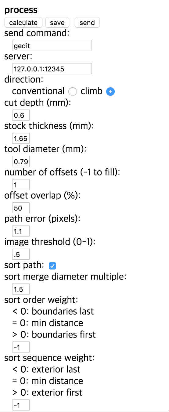
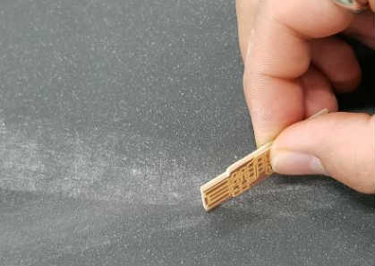
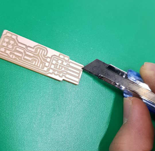
After milling done, I cleaned surface with vacuum cleaner and detached board by using cutter knife carefully.
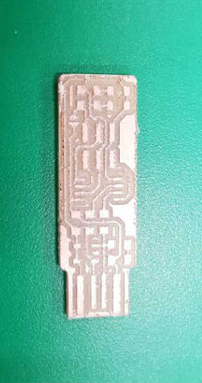
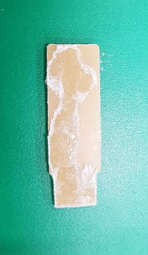
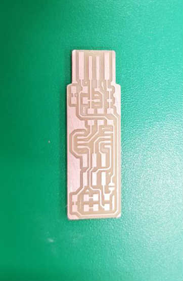
It was fine. i washed the board with soap to wash hazardous substances.
And, I did some finishing work with 800 grit sanding paper and cutting knife.
PCB Soldering
components
Here’s all components to make ISP board.
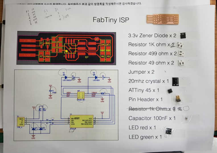
I attached every components I need on the paper printed with circuit and component name not to lose any components. Then I soldered with lead wire.
Solder tips
1. Center to edge
2. Bottom to top
3. Tiny to big
First, I put some lead on the one side. And grab component and hold on the place to attach. Heat lead and when lead melted give pressure component to surface until lead gets hard.
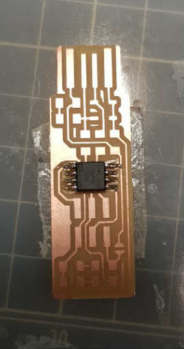
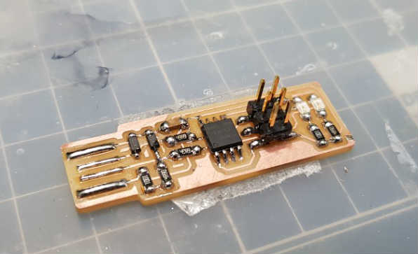
Here’s picture of board I soldered.
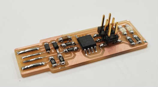
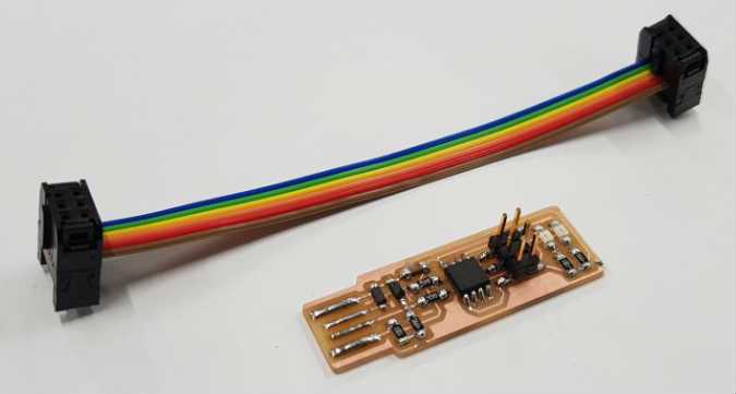
ISP PROGRAMMING
I tried to program my ISPboard I made before.
I followed the tutorial in the class page.
I downloaded firmware file and install Crosspak and Xcode. And I modified the makefile and open terminal and put first command ‘make clean’. But there was error message like this
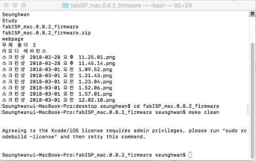
It said about Xcode license and I found Xcode wasn’t installed yet. So I waited for the remain install and put command again.
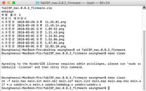
It was fine. It deleted I think some files.
I commanded ‘make hex’. And I found it created some files on directory with extension ‘.hex’.
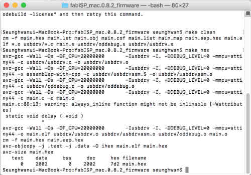
It was fine until this stage but at command ‘make fuse’ there was error message about it couldn’t read the board I made.
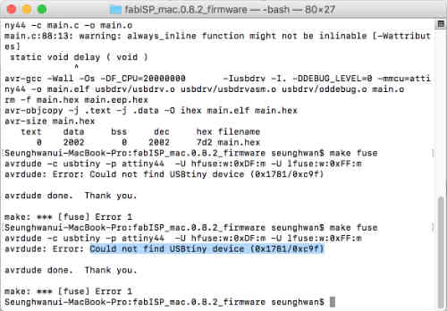
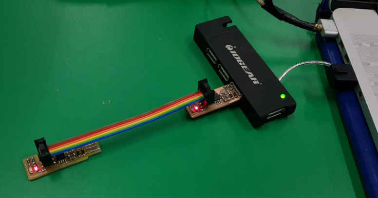
But LED were on both two boards, I thought boards got powered and those were alright. But I checked every components with multimeter for if there was any shorts. But it was okay.
So I asked instructor again and he said try with tutorial by Brian which is in class page at week4. So I tried it. I downloaded firmware again. First, I checked the makefile that make sure it said programmer is usbtiny.

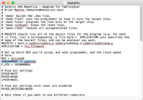
And it was fine. And I put command on terminal ‘make’. After several stages, it created .hex file.
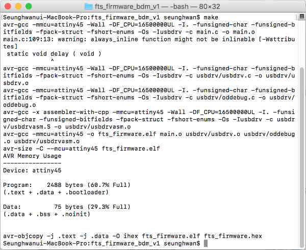
The next step was ‘make flash’ but same error message saying it couldn’t find the board.
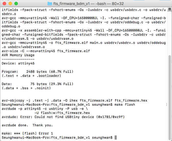
But I didn’t give up and tried once again with another ISP board with ATTiny44.
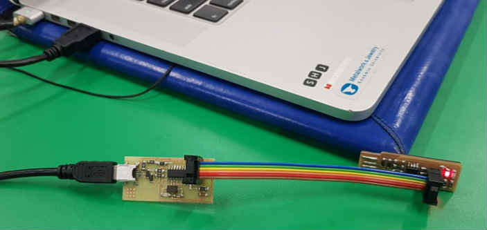
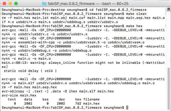
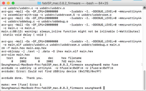
But same error at make fuses. I researched former students and tutorials I found that recommend Linux to program the board.
So I tried to do same process on Linux system. I opened the bash and install avrdude, and modified makefile by gedit.
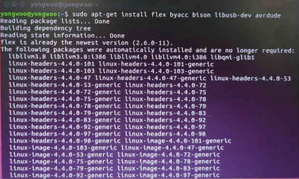
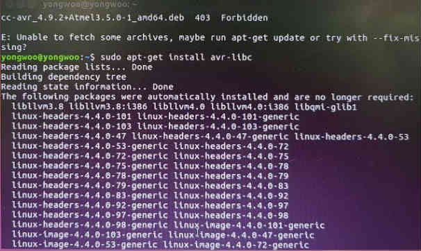
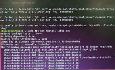
And went to directory and command ‘make clean’. After then command ‘make hex’ but there was error message again.
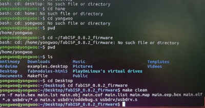
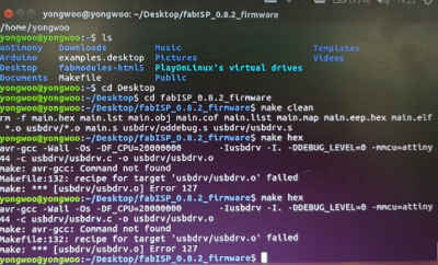
So i tried with different firmware file from brian.
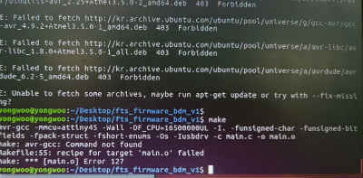
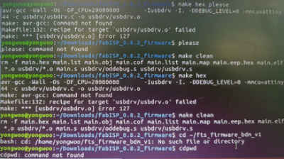
It said it couldn’t find the command and it failed on the file ‘usbdrv.o’. I tried to figure out but I don’t have any application to open .o extension and I don’t know exactly what’s wrong.
After fail on Linux I was so depressed to make another ISP board. And I found someone’s assignment that connect programmed board on computer and connect another board. I thought this is the last trial. I used ATTiny44 and connected this board to computer. And I connected my board to this board. I made sure pin1 to pin1.

And I used fts_firmware_bd_v1 file to make fuses. I commanded ‘make’ and it said it already have the .hex file that I made before.
And I commanded ‘make flash’ which was not work before because it couldn’t read my board. But it worked this time!!!!!!!!!!!!!!!!!!!!!!!!!!!!!!
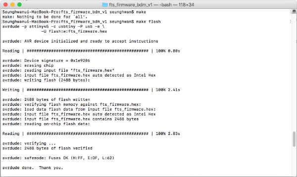
After some messages about reading, writing, reading, the message came up saying avrdude done!
Then I commanded ‘make fuses’ and it went well.
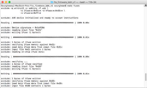
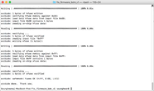
I almost get there. ‘Make rstdisbl’ made reset pin disable on my board. After programmed done, I removed the jumper by leads. Finally my computer read my board as a usbtiny.
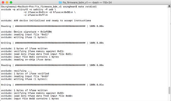
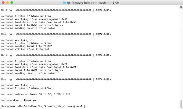
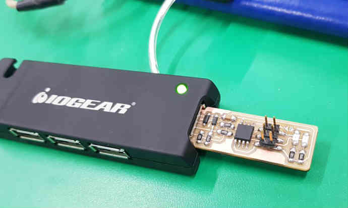
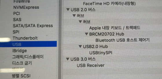
Here are my works.
Download