BOARD
June first week 6/1,2
-according to my plan I designed my board and make a board.
Making board and programming is relatively not my strength. so I did this works first.
I'll use PIR motion sensor and bipolar stepper motor. So I need to design integrated board include both of input and output devices.
BOARD DESIGN
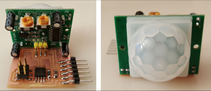
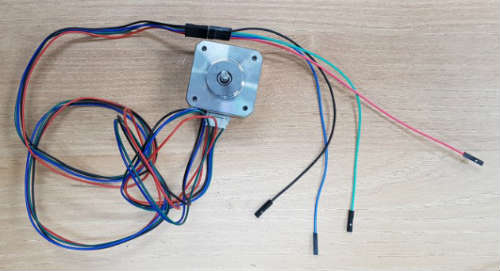
PIR sensor and bipolar stepper motor
BOARD DESIGN
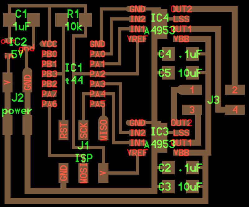
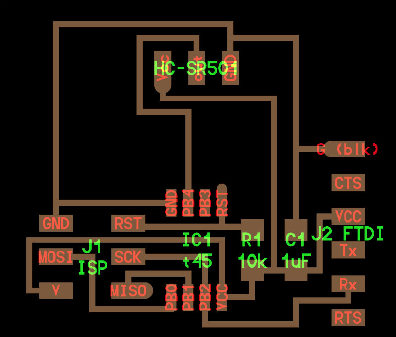
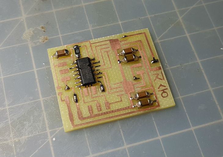
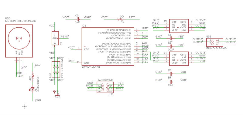
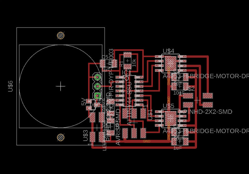
I referenced Neil's boards. These are the boards PIR motion sensor and bipolar stepper motor. I tried to combine those two board in one. For my project, stepper motor will do a bigger role so I added sensor part on stepper board. I designed bipolar stepper board and put HC-SR501 the PIR sensor on it. I connected sensor's VCC and GND to board's and connected sensor's out pin to PB0 pin on ATTiny44. and to make board compact, I placed every components and rotated and create routes. This is my board for final project.
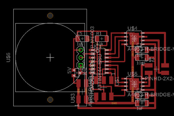
And I exported to image file and modified scale and put my name on it.


I created .PNG files for trace cut and outline cut. For milling, I opened these files at fabmodules and created .nc file.
MILLING
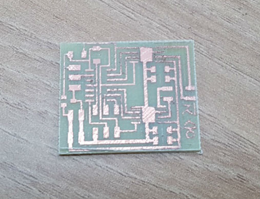
Milling was fine, and i finished with fine sanding paper.
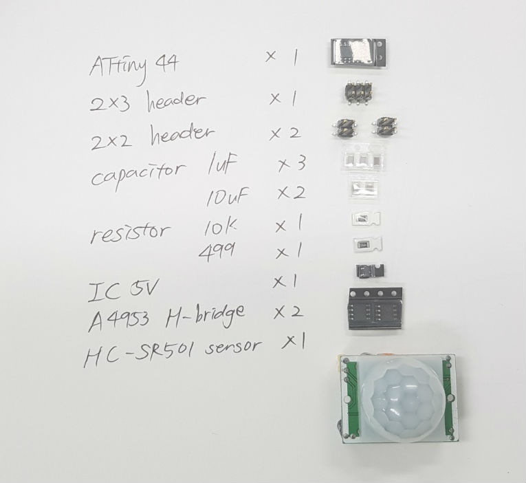
COMPONENTS AND SOLDERING
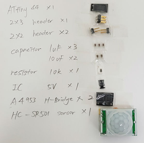
These are all the components I used for this project. I wrote down a list and arranged on paper before soldering.
I stared with thin components to thick and center to edge.
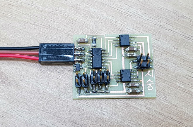
After soldering done. I soldered jumper cable for PIR sensor.
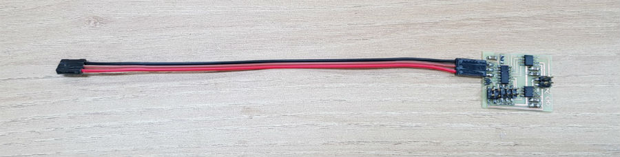
Like this.
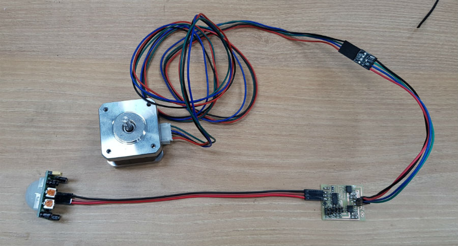
Then I connected stepper motor to each correct pins and PIR sensor.
-I designed second board, milled and soldered components.
COMPONENTS AND SOLDERING
But first board didn't work well. When I connected power, motor rotates well. but with unknown reason sensor doesn't work and motor doesn't rotate.
So I decided to make another board with LED. I added LED and resistor on schematic and connected to PA7.
And I opened board file in Eagle. and routes
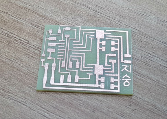
I exported to PNG file and modified scale and shapes.

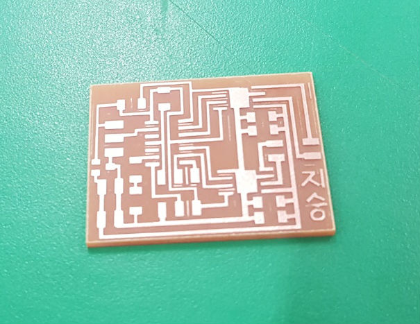
milling was fine.
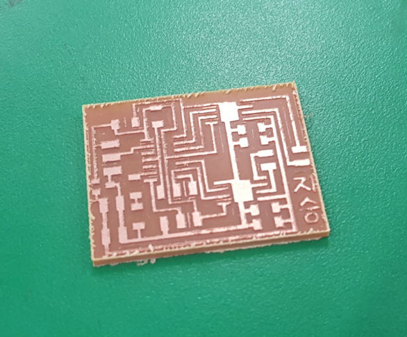
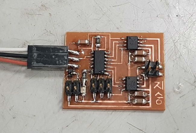
after some finishing works like before I got this beautiful board.
Here's the components I needed.
After soldering.
WHERE I WORK
I'd love your feedback!
Phone: +082 1041950935
Email: jshjshjsh93@gmail.com
Feel free to contact! , or leave me a note: