FINAL PROJECT

Like I mentioned in the previous week, I had changed my mind about the final project late in the course. As I am pretty indecisive, it took a sufficiently long time to think of a new project that I was satisfied with. I knew that my main electronic component would be neopixels as I am interested in working with light as a medium. I was brainstorming different lamp ideas, and working with different types of material. I saw an example of an led in an epoxy cube and thought that it had a really nice look to it. In line with my original project, I wanted to incorporate an element of aiding in the practice of meditation and/or awareness. Focused breathing has been a very powerful tool in helping me with my meditation practice and being able to rechannel my energies. With my yoga students, I have found how this simple act has a profound effect on people in dealing with stress and being more at ease. As I often do many breathing exercises, I've learned effective visual vocabulary with respect to the breath. I decided that I wanted to make a lamp that would cue respiration with the dimming and brightening of the lights. The hourglass design came because it had two separate portions that could be designated for inhalation and exhalations. I also liked the idea of it being the antithesis of an hourglass in which you are directly confronted with the finiteness of time. The lamp would help to reframe our concept of time as it flows infinttely up and down through the glass.
Design
Modeling in Fusion
I am a fan of minimal design so I wanted to keep the hourglass as simple as possible. Since the glass was supposed to help bring about a sense of calm, keeping things as minimal as possible would be the most effective in achieving this I had a lot of restrictions to work with because of the material I would be using. The lamp had to be large enough in the center for the microcontrollers, rings and input to fit into. Due to the hourglass shape though, it was quite a small area. It would have been possible to make the lamp much larger, but I had a limited supply of epoxy resin, and I also didn't want to the lamp to be too heavy.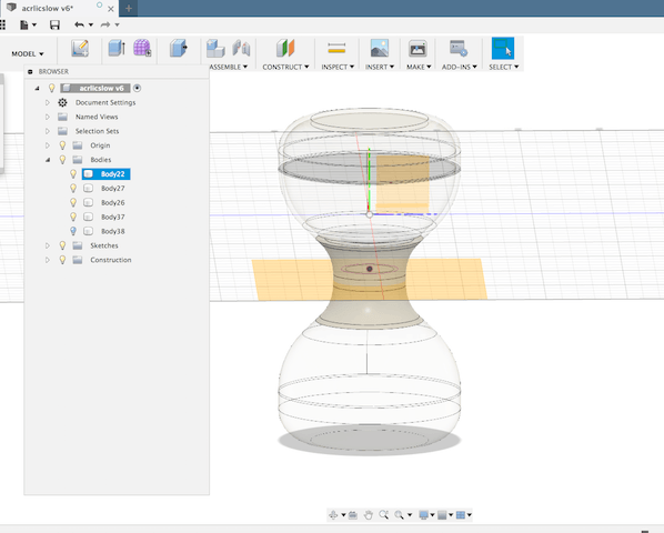
3d Printing, Molding & Casting, Laser Cutting
Because of the size of the hour glass, I decided to make a mold from using a solid object printed in the 3d printer rather than milling in the CNC. I used the lasercutter to make an acrylic box the appropriate proportions to hold my mold. I used the same molding material from Molding & Casting Week .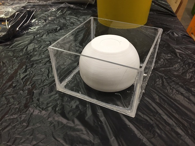
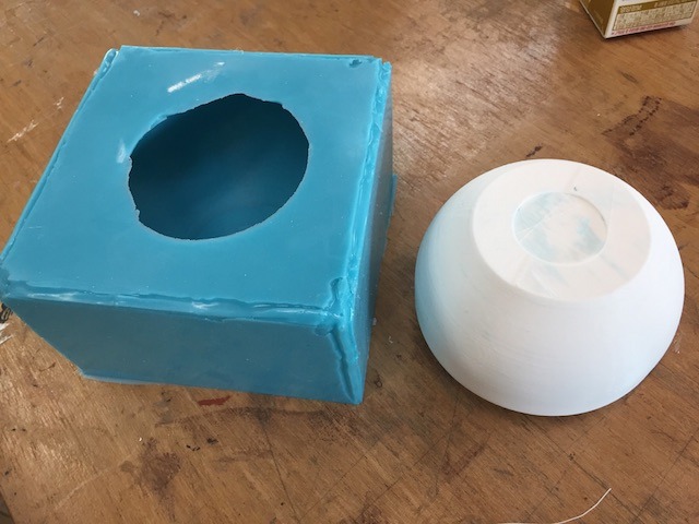
For casting, I used ProMarine Table Top Epoxy as suggested by a friend who works a lot with resin.
Mix Ratio : 1 part Resin to 1 part Hardener by Volume
They recommend a "second mix method". First measure out the ratios in separate containers. Then pour the the hardner into a larger container followed by the resin. Mix for about 3-5 minutes in the first container. Then pour the content into a second container and mix for an additional 3 minutes. Don't stir too vigorously and no longer than 8 minutes as it can cause the epoxy to heat up and self cure. You can remove airbubbles by using a a hot gun and blow it over the the epoxy. Curing time : 12-14 hours to harden but 3 days for complete curing
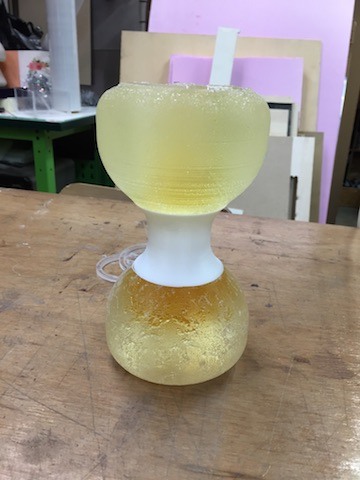
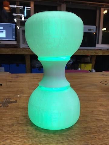
The results were not as nice as I had expected. There were a lot of airbubbles and it had a very frosty look to it. You can also see that there was discoloration from the oil because the mold wasn't fully cleaned out. Unfortunately because the designs were big, I had used up all of the resin. While I had expected that I may have results that I didn't like, I was 3d printing the design using white and clear filament as an alternative material. Even though I had originally printed out the hourglass design to be casted, after seeing it printed I was quite surprised with the results because I thought it looked pretty good. The clear filament filtered the leds nicely and I decided to use this instead of the resin for my fnial design. In retrospect, I should have done a few tests with the epoxy especially since it was expensive and had to be shipped internationally. Also I would sand down my 3dprint so that there wouldn't be any ridges in the mold.
3d printed hourglass
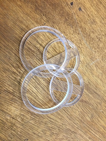
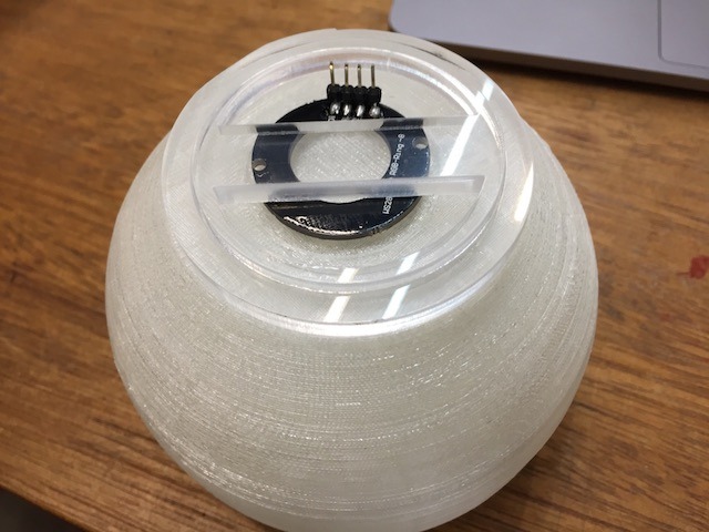
I laser cut some rings as connectors for the lamp and the center portion of the lamp. I also cut out some small LED holders so that they would stay in places. The middle part of the lamp was 3d printed.

Board Design & Production
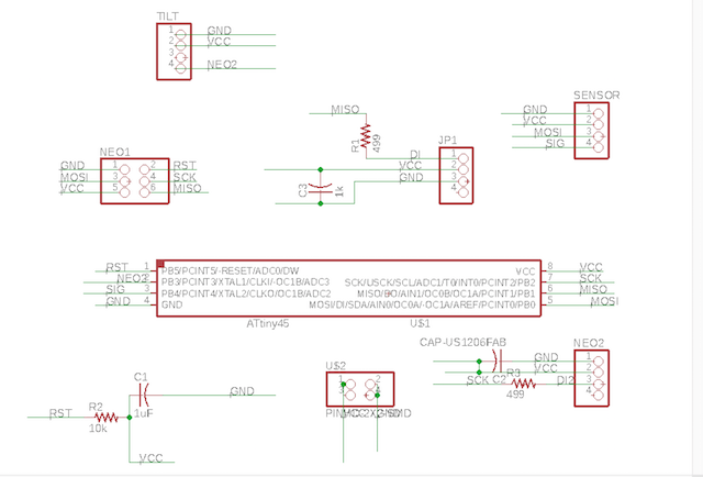
For my board I needed to be able to connect 2 neopixel rings, a capactive touch sensor and a tilt sensor. I was able to the use the Attiny 85 as it had sufficient pins for my components. I made smaller separate boards for the capacitive sensor and touch because of the size restriction of where I would house the electronics. I had done the best job I could smashing all of the components onto the smallest board I could manage. So much so that the a few of the first board cut the circuit lines were merged and I had to cut to separate them. The first board I was able to program worked fine. It was set up for the 2 neopixels and a sensor. My plan was to have a single sensor to control the neopixels. I realized that I had a pin left over and that I could add an additional sensor at later time if I wanted, so I made another board that utilized all the pins on the 85.The capacitive sensor needs to be connected to the attiny through two Digital I/O pins (0, 4) and ground. The copper tape will act as a sensor and be directly connected to pin 4, and to pin 0 through a strong resistor. The larger the resistance, the higher the sensitivity of the sensor. The largest on board resistor we have at the lab is 1m, so I added a few of them to increase the sensitivity.
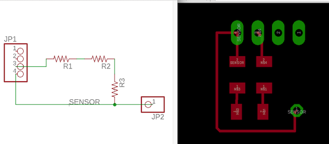
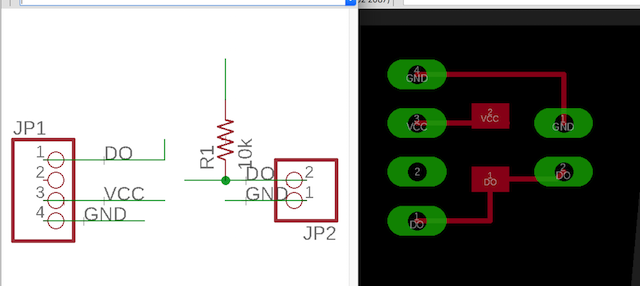
I thought that since I had an extra pin, I would try out another sensor. The tilt sensor worked well with my design as it imitated an ordinary hourglass. I just needed to add a 10k resistor between ground and the data pin on the ball tilt sensor and have the three lines G, V and D connect to my main board.
Main Board
Components List
- AtTiny85
- 10k res -> RST
- 499 res (x2) -> DI on NEOPIXELS
- 1k cap (x2)
- 1x4 Header Pin (x4) -> For I/O devices
- 2x3 Pin -> SPI
- 2x2 Pin -> Power
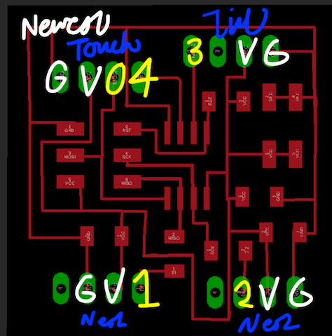
Components

Programming
Neopixel Rings
This is always the most difficult part for me. I've found that the best way for me to not feel overwhelmed by coding is to tackle the most basic of commands one at a time and try to build on them. This takes a significant amount of time and I seem to have trouble even with this, but because it's so foreign to me I have to simplify it the best I can to be able to get to a place where I feel like I can accomplish anything with it. I started out with trying to get the neopixels to run the function I wanted.I ran some sketches on the neopixel board from their library and tried to study how the code worked. It was a bit difficult actually trying to find out how to change the brightness to get the lights to dim as I had read somewhere that using set.Brightness wasn't a good function for animation. After some searching, I found a great Pixel breathing made by Jason Yandell. This was a good place for me to start because this was the effect I wanted to create with my lights. The breathing effect is based on the function
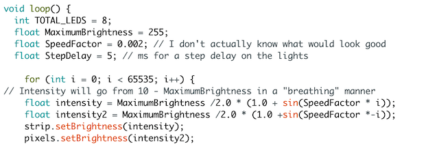 Change the value of speed function to slow it to your liking. In order to the opposite relationship of the two rings, I need to loop separate functions for each ring, making one result in the inverse value of the other.
Tilt Sensor
The tilt sensor are a simple switch that sends out high/low digital signals. Inside are small balls that when connected create a conductive path to complete the circuit. When the connection is made, it will send out a high signal state. There is a delay to eliminate signals that might incorrectly be interpreted as a state change.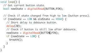
Capactive Sensor
Add capacitive library. The library utilizes two pins (0 and 4) that are connected from the sensor to the AtTiny. It will set the send pin to the sensor to a new state and wait for the receiving pin to input the same state change. When the sensor comes into contact with skin, it creates a delay between the state change being trasmitted versus that of being received.
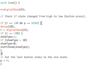
The code for the capactive sensor looked really similar to the button state code for the tilt sensor. The processor sends out the state change from pin 0, and waits for the input from pin 4 to indiciate a state change. If it detects a state change it will delay and then reread the state change. Then it will reset the last send pin to the old state. If it was a true change, then it will run the loop of you rmaking. Every time you touch the sensor, it will cycle through the different showtypes, or colors. When it reaches the last show of the cycle, it will start all over again.
To get the final results, I kept building on the code little by little, combining and failing and then repeating. Although, I think I need to figure out a better workflow because after every little success, I would need to save the sketch, which got very confusing because I couldn't remember which sketch did what. Towards the end, I spent a significant amount of time looking through the 10 open sketches on my desktop to find out which was my last successful upload.
I am really pleased with the results of my breathing glass. I will like to continue modifying the design, trying out different sensors possibly and lighting options. I will also experiment with different materials for the lamp and have another attempt at the epoxy resin because I still really like the look of it.

