

WEEK 9
Embedded Programming
Equipment
- Hardware:Roland Mill
- Software:Arduino
- Material:PCB Board
DataSheet
I attempted to read through the datasheet and I can't say that I was able to comprehend most, if any of what was read. I don't know if I can call it reading more so as looking at seemingly familiar words and being puzzled as to how I couldn't grasp the combination of them together. It was incredibly frustrating. I desperately hoped that it would make sense to once I started working more with the microcontrollers. These are some of the few elementary elements that I was able to gather from the data sheet.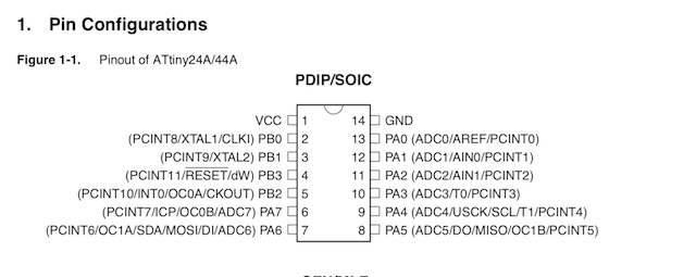
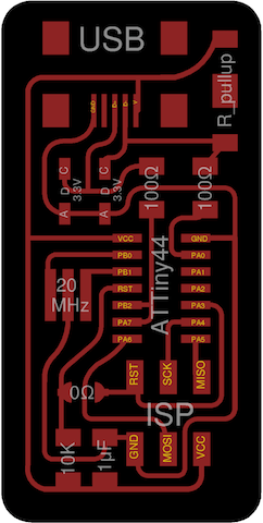
ATTiny 24/45/85 is an 8bit AVR microcontroller by Atemel with a operating voltage of 1.8- 5.5 V. I has 1 VCC, 1, G, 4 PORTA pins (8 bit bi directional I/O) and 8 PORTBs Pins (4 bit bi directional) and a reset.
Port A can also serve alternate functions to I/O pins such as Analog to digital convertor, External analog reference, pin change interrupt, Timer/ Counter, Serial interface, MISO (master Data Input), MOSI (Master Data Output).
Port B pins alternative functions include crystal input, pin change interrupt, time/counter, reset, external clock input, system clock output
It is an AVR Architecture with 2K/4Kb on-chip in systen reprogrammable flash memory for program storage, 32 general registers, 64 i/o registers and 128/256 bytes of internal data SRAM, and 128/256 bytes of data EEPROM memory located in a sepearate data space which can read/write single bytes.
Arduino IDE
Set up environment
-
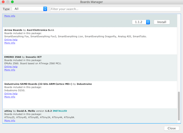
Add Additional Boards to Board Manager
Install ATTiny Board
-
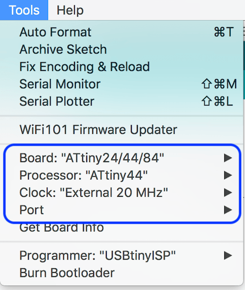
Select appropriate environment for programming
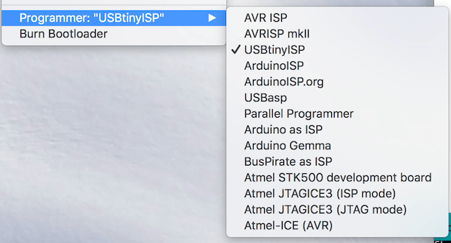
Select programmer
Burn Bootloader

Programming Echo Board
Initialize variables
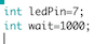
For Arduino, the ledPin is 13, so we have to change this for our ATTiny board. This names pin 7 as our ledPin. wait=500Set up PinMode
-
digitalWrite
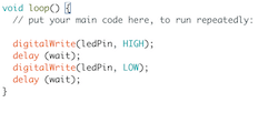
(ledPin, HIGH); gives command to send 5v signal to ledPin which will turn the LED on
(ledPin, LOW); will turn the LED off
delay(wait); will keep LED light on/off for the number of milliseconds that we've set for wait in this case wait=1000; (as defined earlier) so it will stay on/off for 1000 milliseconds
*Note: the reason that we need to use delay to have the light blinking is because the CPU is processing so quickly that if it's not told to delay, it will run the command so fast that our eyes can't perceive the change and it looks like a constant dimly lit LED
>
Upload

Compiles & uploads code to board
Hello Button
Programming FabKit 2.0
-
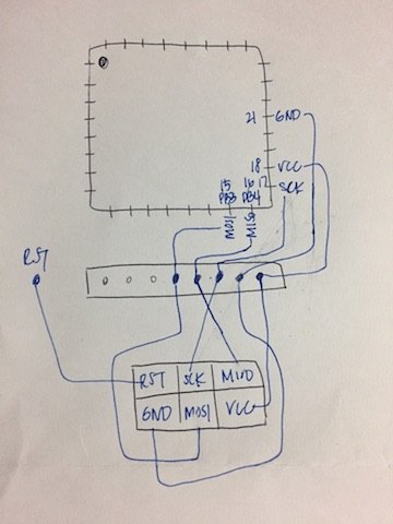
Connect FabKit to ISP
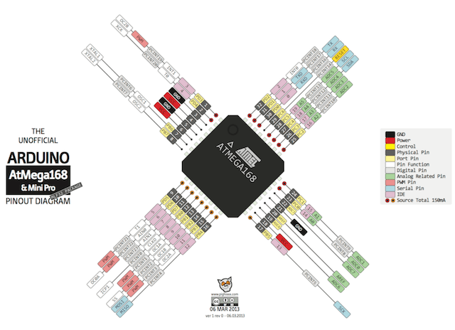
Compare the ATMega data sheet with the ATTiny board to match the pin connections.
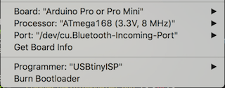
Set up environment for ATMega
Run Bootloader
Blinking FabKit
-
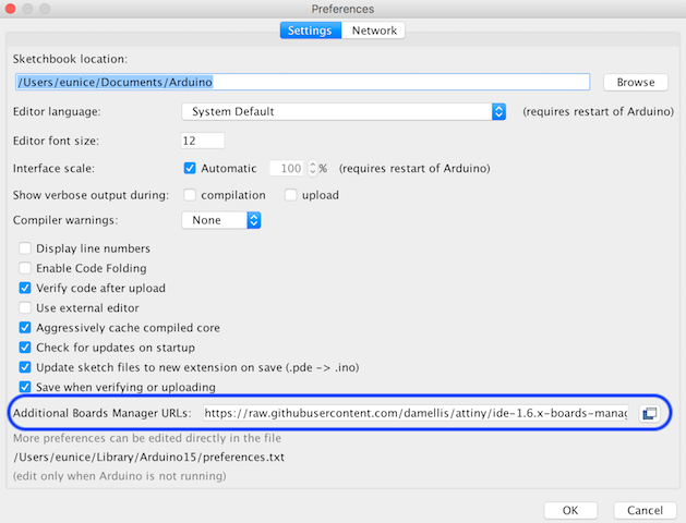
Under Preferences -> Settings, add: https://raw.githubusercontent.com/damellis/attiny/ide-1.6.x-boards-manager/package_damellis_attiny_index.json to the Additional Board Manager URLs
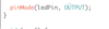
Our ledpin (pin 7) on the ATTiny is connected to the LED, so we want to set up this pin as the output
Git Bash
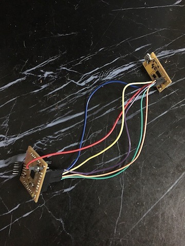
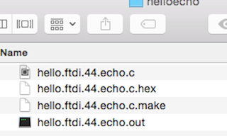
Connect the FTDI to the EchoBoard which connects to the computer via the FabISP Programmer. Download the Make and C files
hello.FTDI.44.echo.c hello.ftdi.44.echo.c.make Put these files in a folder on the desktop called HelloEcho.
From your terminal, cd into the HelloEcho folder and run the command:
make -f hello.ftdi.echo.c.make
This will create a hex file which contains the information of the code in a binary form.
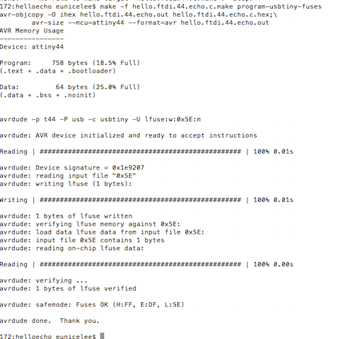
I had burned the bootloade once in Arduino IDE which needs to be done at external 20MHz. If you haven't burned a bootloader, you can also set your fuses in the command prompt. From what I understand this is similar to the bootloader as it sets sets up an environment for the program to execute and establishes things like baud rates and clock speeds. You can set fuses by running the command:
make -f hello.ftdi.44.echo.make program-usbtiny-fuses
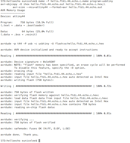
Run make -f hello.ftdi.44.echo.c.make program-usbtiny
This will upload to the C Code to the Echo Board.
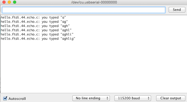
Disconnect the the Echo from the FabISP and reconnnect it to the computer using the FTDI. Then go into Arduino IDE, select the serial port and open your serial monitor. Make sure you set the baud rate to 115200. Type something and you should see the code running.
Troubleshooting
-
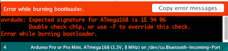
Error Message: Expected signature for ATmega168 is 1E 94 06
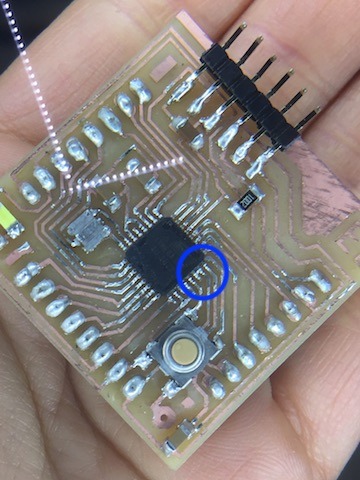
I googled what this message meant, but couldn't understand the language being used. It sounded like it might be with the hardware itself, so I took another look at my soldering. You can see there was a bit of solder between two pins.
After removing the solder I got a different error message.
avrdude: initialization failed, rc=-1
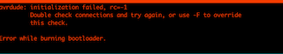
I checked my connections multiple times. I was reading the websites of past Seoul lab students and they reported that they had used the wrong ATMEGA and thought that this might be the issue. Sure enough, when I asked my instructor about it, he said that the chip should say ATMega328P NOT ATMega328AU. History repeating itself over in the Seoul Lab. I learned that I should thoroughly read past websites before delving into the homework to avoid these types of silly mistakes.
Because there are so many pins on the ATMega, I used a hot air blower to heatup the connections together. You need to move around the Mega, not staying on one place too long and evenly heating up the pins. You have to be careful because if you keep the heat in one area too long, you can risk burning the controller. This took about 5 minutes for me to safely remove the Mega. Then I changed it to the correct controller, ran the bootloader and it worked! WHOO!
AtTiny Not Found
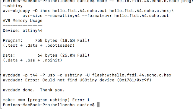
This one again took me a while to figure out. Then I remembered that I had some difficulty before with my USB hub not reading things correctly. (My laptop doens't have USB port so I have a hub that connects to my computer through firewire) Once I switched everything over to my old laptop with a regular USB port, everything worked fine. This is quite an annoyance as my old laptop is very old and slow. Also because I have to keep going back and forth between two laptops which makes things confusing and can get disorganized. I think until I figure out how to fix this so that I can read programs through my terminal, I will stick to using Arduino IDE to program my boards