WEEK 7
Electronics Design
EAGLE
-
Add Fab Library
First download the Fab Library containing the components we'll be using for the class.
Open Application-> Eagle -> Lbr and add the downloaded Fab Library.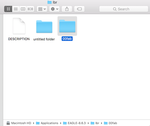
*Note- Rename your fablibrary to 00fablib. This will have it show up on the top of the list which eliminates confusion and having to scroll through the library list.
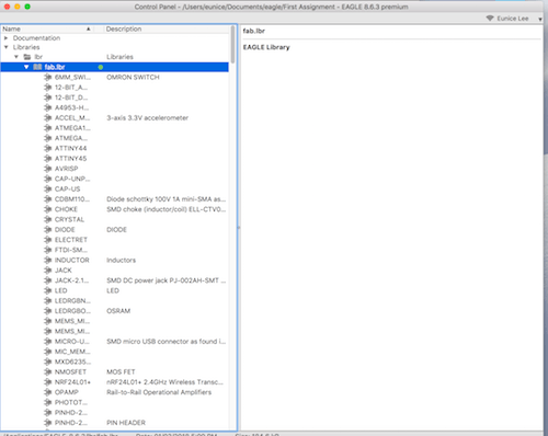
Open Eagle and under the Windows options, click Control Panel.
Under Libraries -> lbr, you should see fab.lbr with a list of components underneath. The fab.lbr should have a green dot next to it to show that it is active.
-
Create Schematics
Add Components using Fab Library
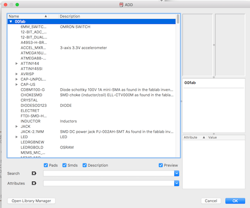
Type Add to bring up the components library. Choose the Fab library from the list and select the components you want.
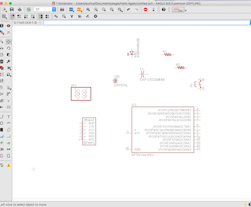
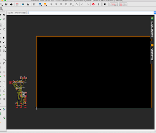
Connect Paths using NAME
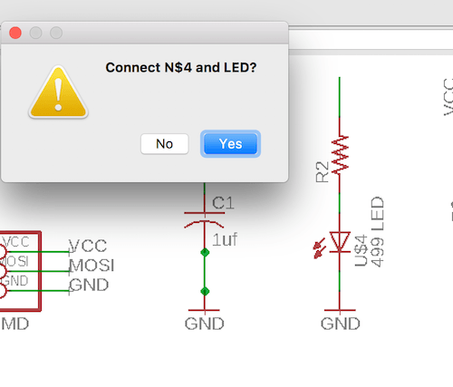
NAME the paths you want to connect.LABEL paths
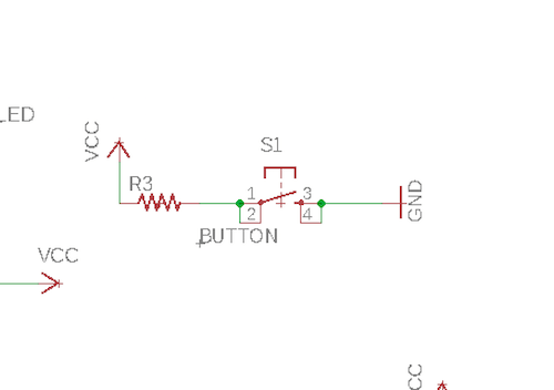
LABEL items to make the schematics easier to readCompleted Schematic for Hello Echo
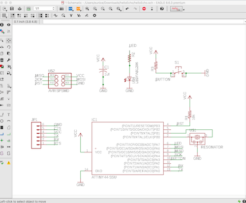
-
ERC
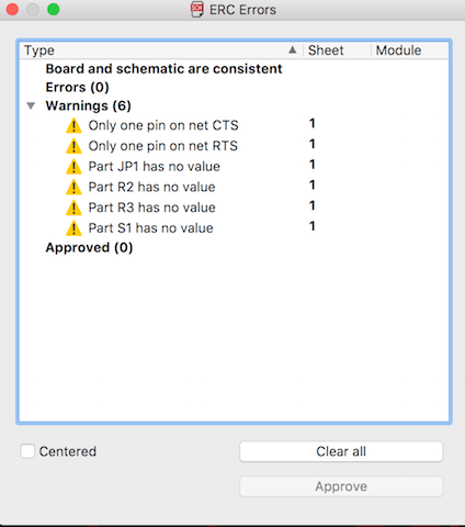
When you've finished the schematics for your board, do an Electric Rules Check (ERC). This will let you know of any connectivity issues and will ensure that you board is capable of working properly. Fix any errors that the ERC points out.
-
Create Board
Switch from Schematic to Board view. You need to keep the schmatic window open or it will also close the Board.
The added components should appear in the bottom left corner of the window connected by yellow lines.
Adding Components to Board
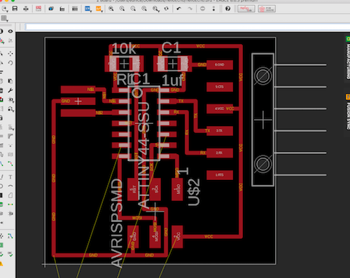
Drag the components on the board. In the free version of Eagle, the workspace can only be to Right and Above the Origin X mark.Auto
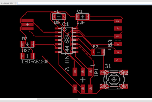
You can use auto routing.
Type ripup; in command box to undo all routesChanging grid
Adjust the grid so that you are working with smaller increments when moving around items. This makes it easier to create paths around the board.
View-> Grid

Create Paths
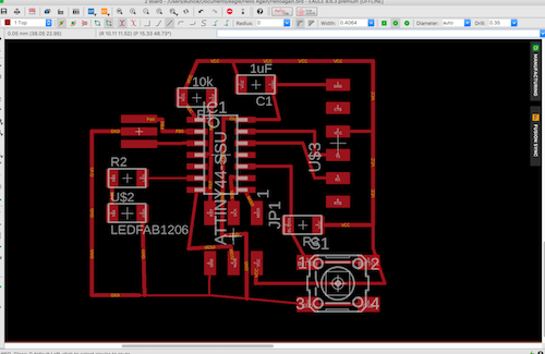
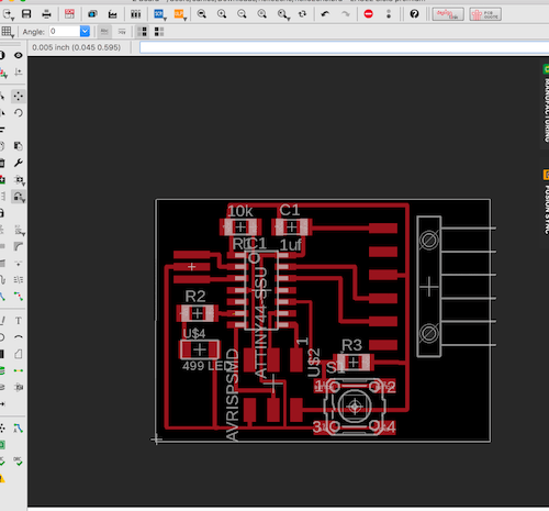
Completed Board
DRC
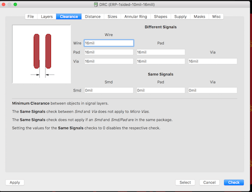
You can set certain design properties for your boards such as minimum size of paths, distance between wires, and other design related restrictions. When you've arranged your board, you can run a Design Rules Check to make sure that your board design falls within the restrictions set by your design rules.
Export Images
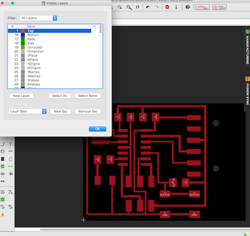
View -> Layer Settings select only the top layer to be visible.

Select Monochrome. Resolution= 500 dpi. -
Create PNG files
Traces
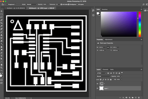
Crop as needed.
Outline
For outline- Create a new layer with the background black. Select the area of the traces, and remove so that you get only a black border.

* Note- keep the layers the same size. I initially forgot this and cropped out the outline of the trace file making it slightly smaller. Export Traces & Outline Layers as png for milling. Create RML using FabModules
Dimensions too big
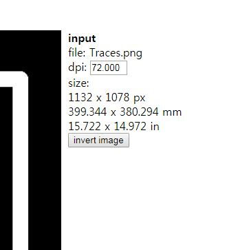
Check your dimensions. It said my board was to be almost 400 mm, which is clearly way too big. I went back to check where I went wrong in scaling.Matching Canvas Size to Eagle's export dimensions
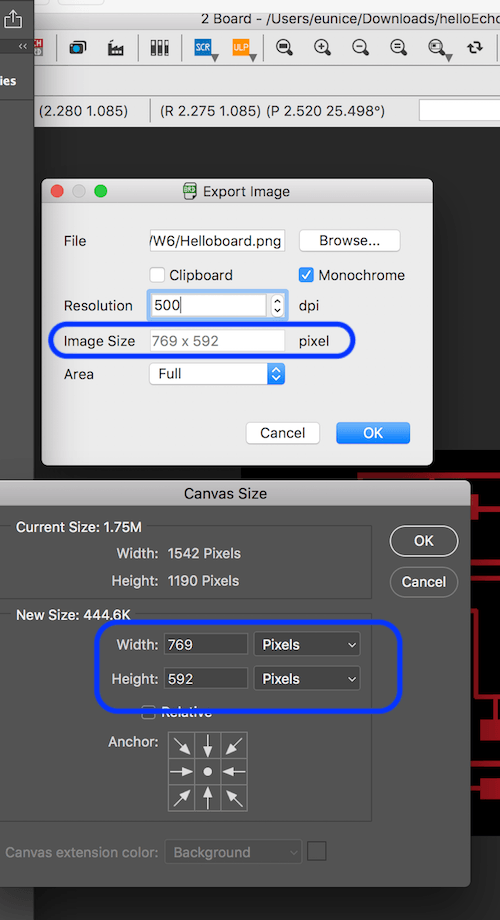
In Photoshop, I went back to check the dimensions of the Eagle file upon exporting. I changed the canvas size to match the Eagle files.Correct Size
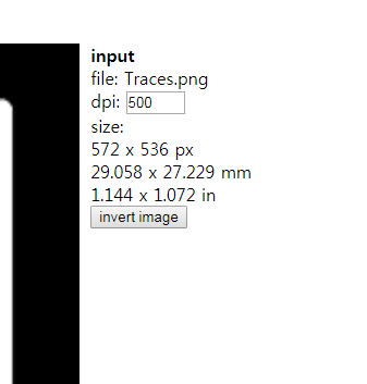
Corrected. Also change the DPI to 500.Complete Board Production
Milled Board
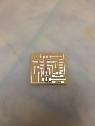
Components List
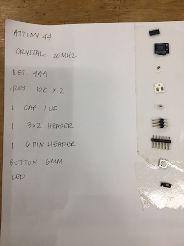
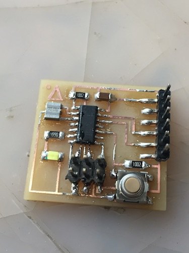
Finished Board
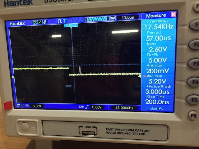
Oscilliscope
One of my labmates who is an electronic engineer kindly offered to explain what it does and how to use it. From what I understand it observes the voltage signal over a period of time which is useful to find out if there is power being run through all of your lines at the correct rate. We have been using the multimeter in the lab to test whether or not there are breaks, or accidental joints in our wires and also to test for functioning resistors and capacitors. The oscilloscope gives much more detailed information about the electrical signals running through your lines. You can use this for debugging to find out if the voltage signal is being sent to the appropriate data pins.We soldered a small piece of wire to the echo pin of a sonar sensor board so that the oscilliscope could take a reading traveling from the pin. From the oscilliscope he connected a point to ground and to echo while it was connected to the computer which gives of a 5V power supply. We could watch the voltage coming in from the sensor. We could see that the as the an object moved closer, the voltage width would get shorter.

Troubleshooting
-
Airwave Errors
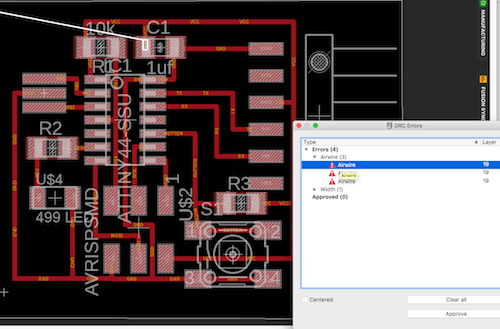
Few airwave errors. I believe these are lines that don't have paths connected to them. They were hiding behind. I deleted traces of unconnected lines to fix the errors.

