Output Devices
So for this week I started with making a
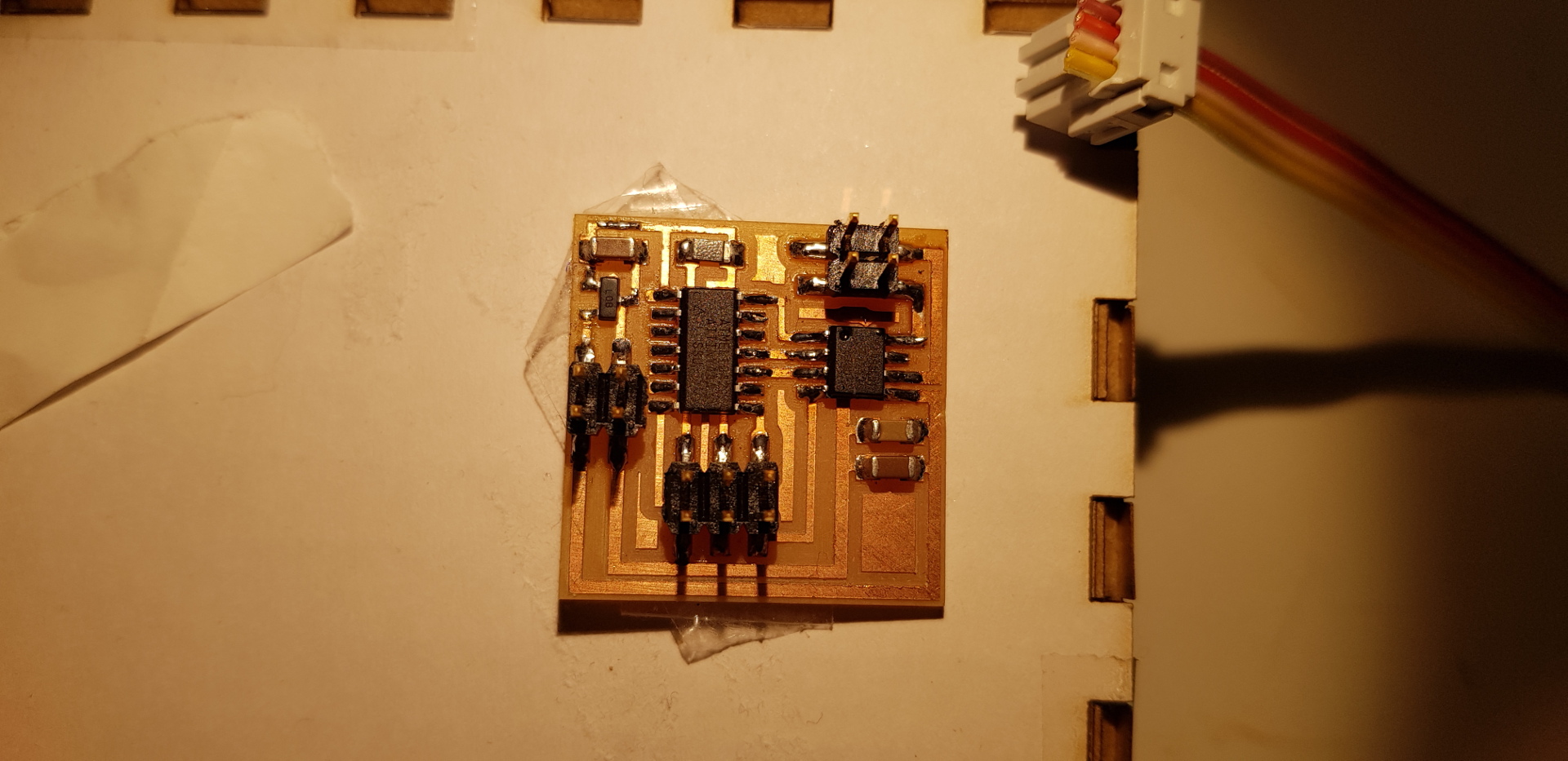
DC motor control board from Neil. I did this to understand the workflow since I want to make my own for my final project later on.
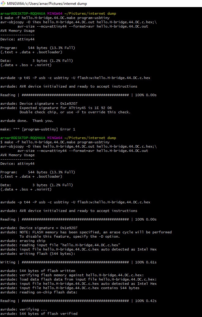
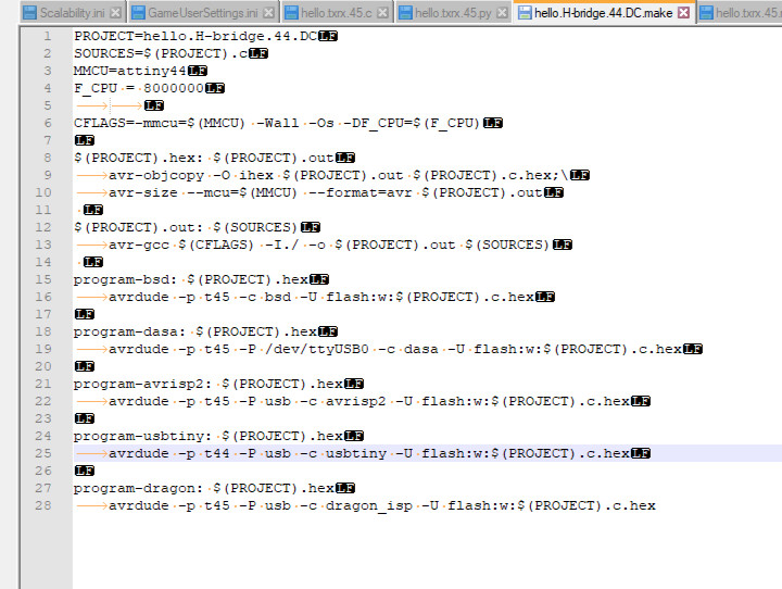
 I had trouble at first with trying to program the board and got an error message "make: *** [program-usbtiny] Error 1" and I searched through the FabAcademy archive for a solution to that error. I found out that the code was using three spaces insted of 1 tab.
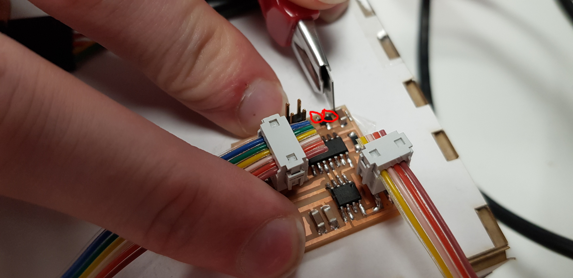
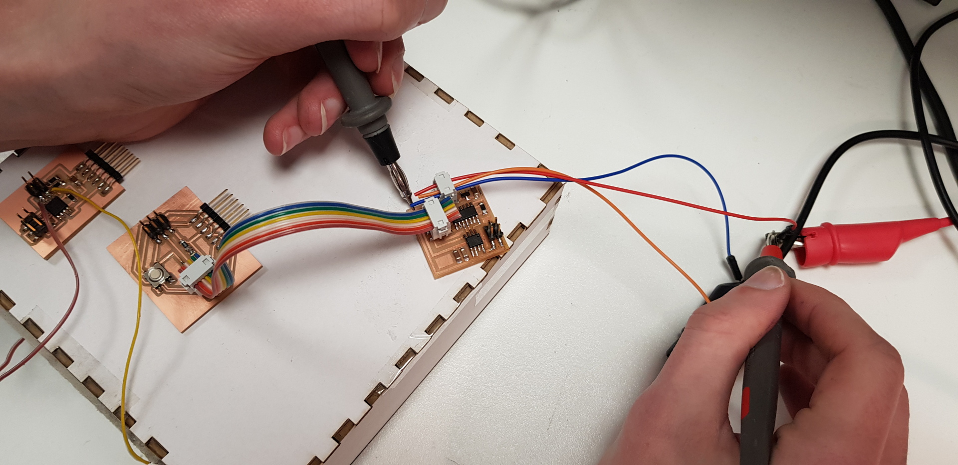
 After that was fixed I tried hooking up the motor and used the power supply to run the motor. It didn't work so me and Bas looked at the board and saw that the power is going into the regulator from the wrong side. I cut off the connection as shown in the picture and I also used the multimeter to mesure the continuity of all connections.
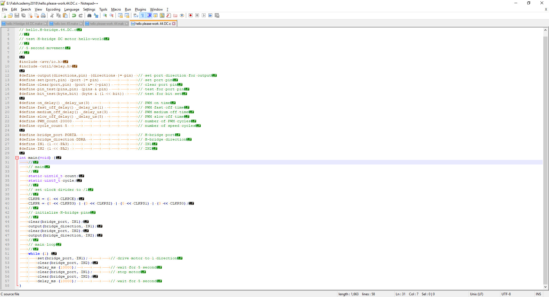
 After that I changed the code from Neil so it would run for 10 seconds and be idle for 10 seconds. The motor runs constantly and the reason is still unknown.
 After output week I decided to change my
final project concept.
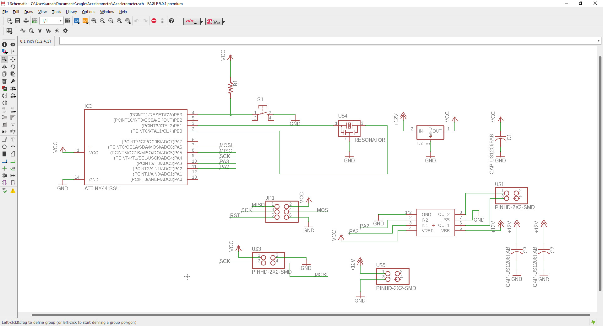
For the new project I also needed a DC motor board.
(screenshot of eagle schematic and highlight pins)
When I first made the board I didn't calculate for the spacing between the pins. So I had to move them so I could connect them side by side. So I had to make a new board again.
After output week I decided to change my
final project concept.
For the new project I also needed a DC motor board.
(screenshot of eagle schematic and highlight pins)
When I first made the board I didn't calculate for the spacing between the pins. So I had to move them so I could connect them side by side. So I had to make a new board again.
 I put in a simple code that I found
online
to see if it worked. I deleted all the "pwm" codes since it was not necessary and played with the delay values. And it ran like a charm.
I put in a simple code that I found
online
to see if it worked. I deleted all the "pwm" codes since it was not necessary and played with the delay values. And it ran like a charm.
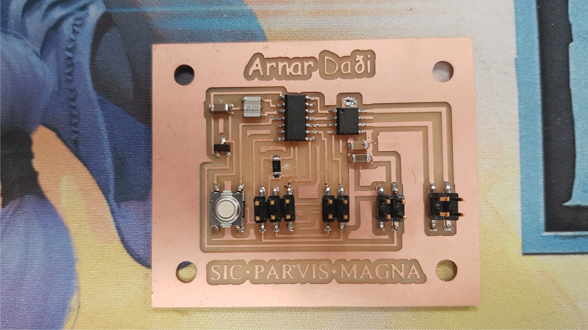
 Later on I added a button to my project, so the motor runs when I press the button.
Motor Test arduino code
Later on I added a button to my project, so the motor runs when I press the button.
Motor Test arduino code
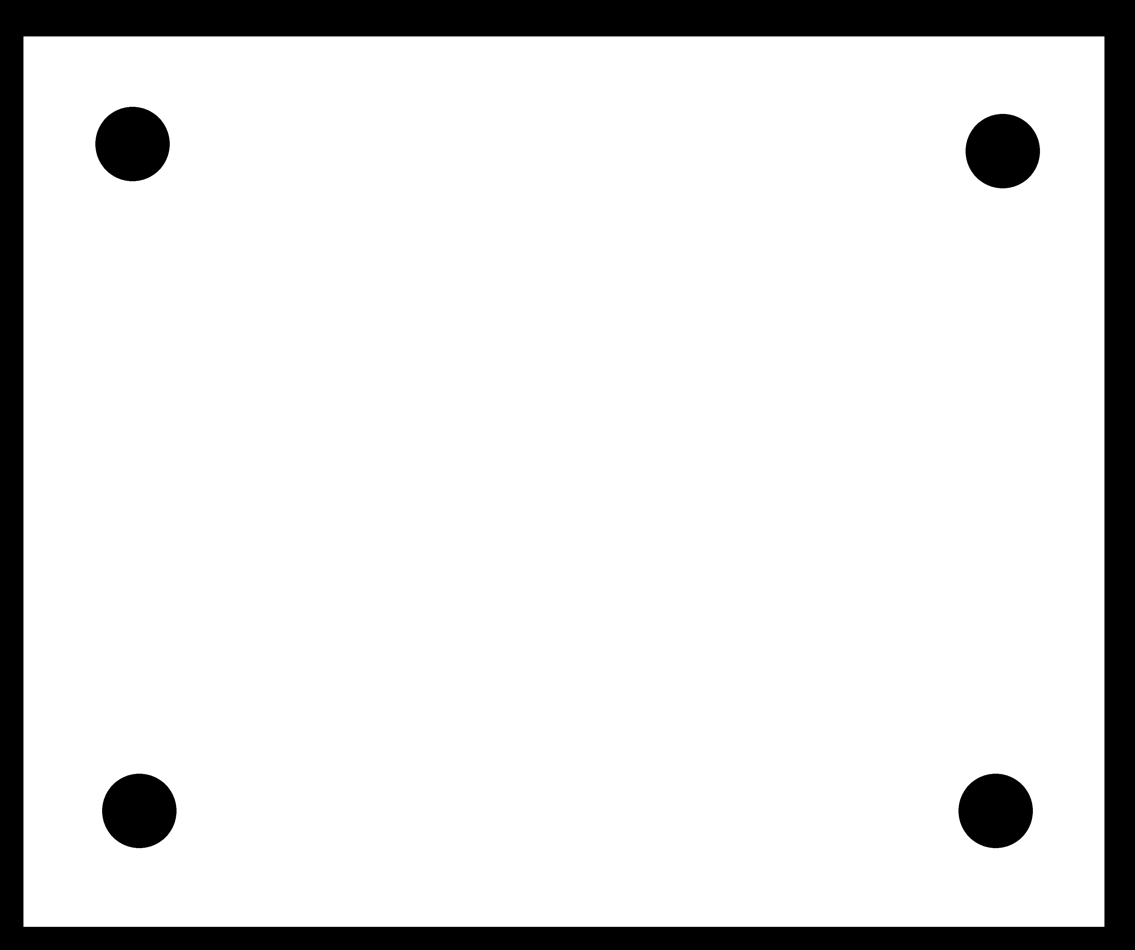
Board Outline
Board Traces
Eagle board file
Eagle schematic file