Week seven: Electronics design
Group assignment
As always I started this week's asignment by downloading the software I'll be using to design electronics. In this case it's going to be Autodesk Eagle, and as all the previous Autodesk woftware I used my students license.
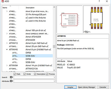
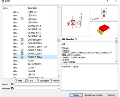
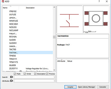
I created a new project, and from there a new schematic, I imported two libraries from my Fab Guru so I had the electronic components we have in the FabLab.
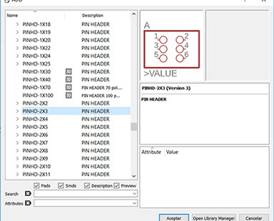
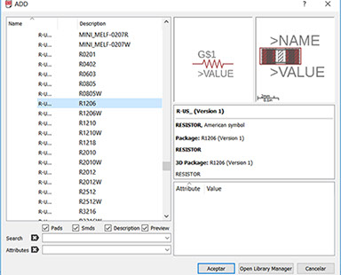
I used an Attiny 45, a blue LED, six ICSP pinouts, one 220 ohm and one 10 k resistors and a push button for this circuit.
So I imported all the components, connected and arranged them.
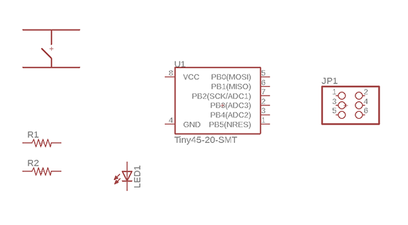
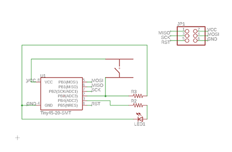
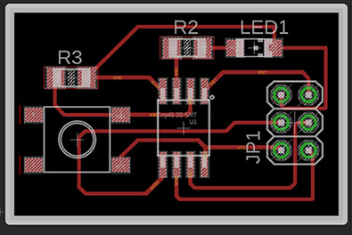
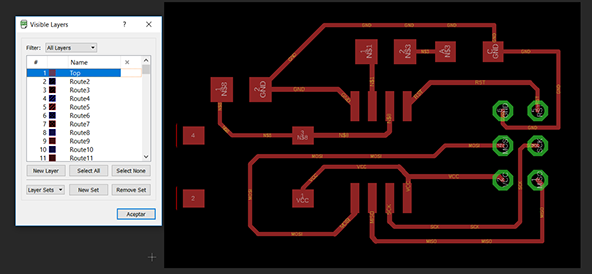
I then generated a board and followed the paths to make all the conections, tested the circuit for conection errors and ended with something like the first image.
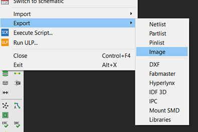
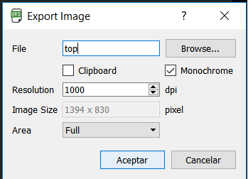
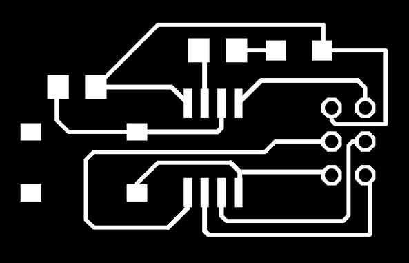
After, I hided all the layers but top and pads, exported the file as an image, selected Monochrome and maximum resolution and ended with a PNG ready tu cutt.
<
>
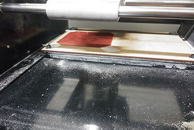
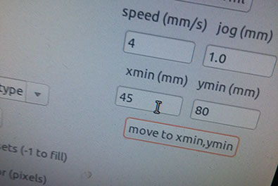
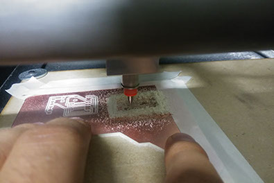
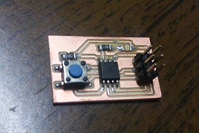
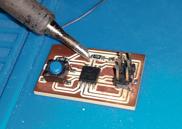
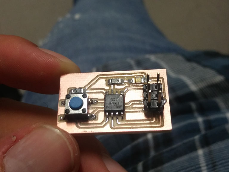
I prepared a copper PC board, setted the parameters and started cutting, I then soldered all the components and tested for shorts.
I'm starting to enjoy soldering and I think i'm getting pretty good at it.
<
>
For soldering I pre-heat the iron to 380 Celsius, put my components in place, put just a drop of solder in the copper path and push the component into place, then I solder the other parts of the component.
The parts list is:
- A push button.
- A 2200 Ohm resistor (Positioned in R2).
- A 10K Ohm resistor (Positioned in R3).
- An ATtiny 45V.
- An LED.
- 6 pinheaders.
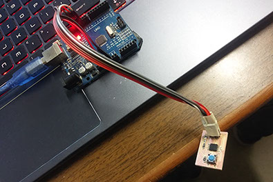
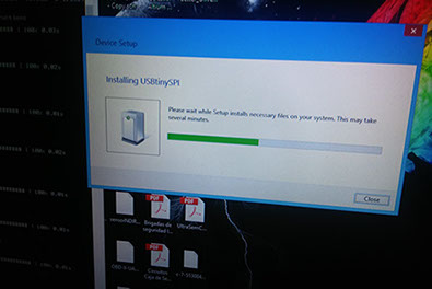
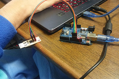
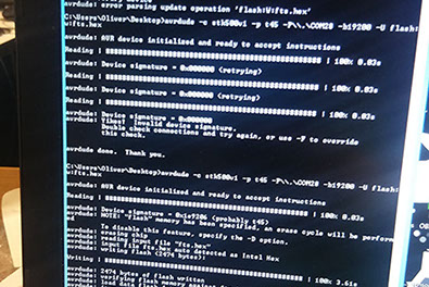
At first I programmed my Attiny with an arduino UNO successfully (first video), so I tried to use my programmer cuircuit to try and do the same also successfully and ran two different programs (second video).
So now I know my programmer circuit works and also I can now program different circuits with it, including this little guy.
<
>
EXTRA CREDIT
