Week fourteen: Networking and communications
For this week I builded a network of 3 processors connected between them by wire.
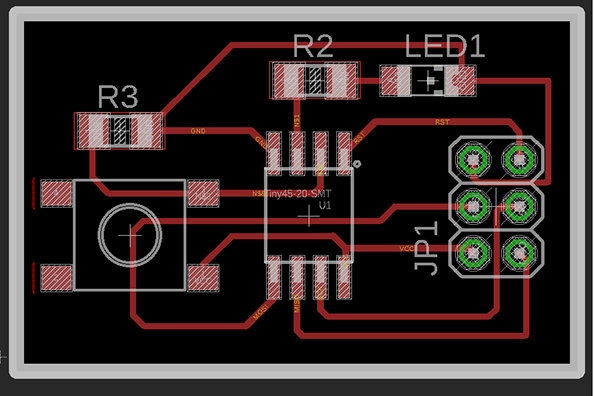
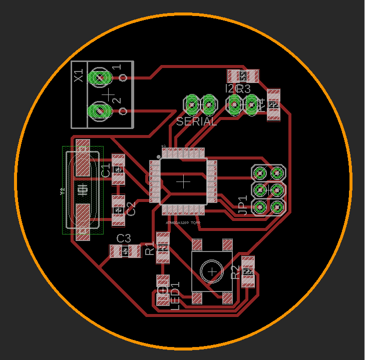
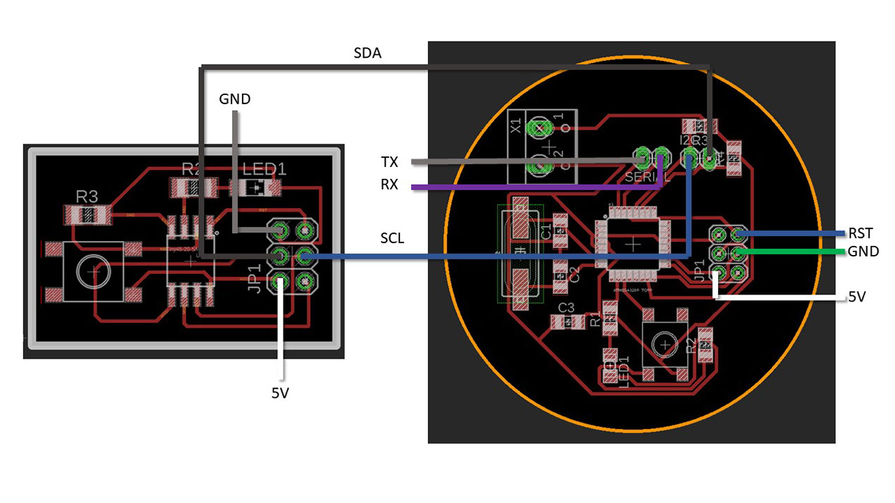
I used the board made in week 7 "Electronics design" and also I made another one similar but adding 2 extra pinheaders so I could connect them with the last board wich is an Atmega328p.

For this week I builded a network of 3 processors connected between them by wire.
I used the board made in week 7 "Electronics design" and also I made another one similar but adding 2 extra pinheaders so I could connect them with the last board wich is an Atmega328p.
The list of components of the first two boards is in week 7, for the Atmega328p board I used:
- An HC49UP Crystal.
- An Atmega 328p microcontroller.
- A button.
- A LED.
- 2 10 kOhm resistors (R2 and R3).
- A 100 Ohm resistor (R1).
- A 10.2 kOhm resistor (R4).
- 2 100 mf capacitors (C1 and C2).
- A 200 mf capacitor (C3).
- A 2x3 pinheaders.
- 2 2x1 pinheaders.
- A screw terminal.

I used an Arduino UNO without its chip for programming the boards, I kept the arduino without chip to use for extending the pins in my arrange, I should have used a protoboard but in order to save some time I used this chipless arduino.
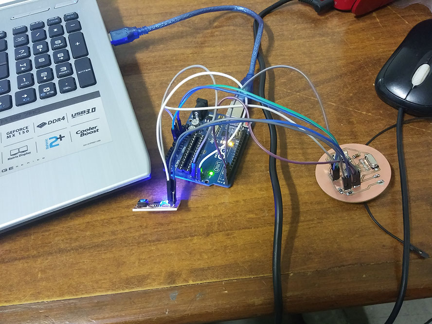
Above there is an image of the boards connected and below is the wire diagram.
Programming
For programming the boards I found an arduino program in this forum: https://forum.arduino.cc/index.php?topic=433407.0 wich is an example of ATtiny I2C slave recieving and sending data to an Arduino master (wich later I'm going to turn in to an Atmega board). I used this program for both the ATtiny 45 boards, I highlighted in green the things that where changed.
Original
Modified
/* ATtiny85 as an I2C Slave BroHogan 1/12/11
* Example of ATtiny I2C slave receiving and sending data to an Arduino master.
* Gets data from master, adds 10 to it and sends it back.
* SETUP:
* ATtiny Pin 1 = (RESET) N/U ATtiny Pin 2 = (D3) N/U
* ATtiny Pin 3 = (D4) to LED1 ATtiny Pin 4 = GND
* ATtiny Pin 5 = I2C SDA on DS1621 & GPIO ATtiny Pin 6 = (D1) to LED2
* ATtiny Pin 7 = I2C SCK on DS1621 & GPIO ATtiny Pin 8 = VCC (2.7-5.5V)
* NOTE! - It's very important to use pullups on the SDA & SCL lines!
* Current Rx & Tx buffers set at 32 bytes - see usiTwiSlave.h
* Credit and thanks to Don Blake for his usiTwiSlave code.
* More on TinyWireS usage - see TinyWireS.h
*/
#include "TinyWireS.h" // wrapper class for I2C slave routines
#define I2C_SLAVE_ADDR 0x1 // i2c slave address (38)
#define LED1_PIN 3 // ATtiny Pin ESTO ES LA 1 PLACA
void setup(){
pinMode(LED1_PIN,OUTPUT); // for general DEBUG use
TinyWireS.begin(I2C_SLAVE_ADDR); // init I2C Slave mode
}
void loop(){
byte byteRcvd = 0;
if (TinyWireS.available()){ // got I2C input!
byteRcvd = TinyWireS.receive(); // get the byte from master
if(byteRcvd == 1)
{
digitalWrite(LED1_PIN,HIGH);
}
else
{
digitalWrite(LED1_PIN,LOW);
}
TinyWireS.send(byteRcvd); // send it back to master
}
}
void Blink(byte led, byte times){ // poor man's display
for (byte i=0; i< times; i++){
digitalWrite(led,HIGH);
delay (250);
digitalWrite(led,LOW);
delay (175);
}
}
/* ATtiny85 as an I2C Slave BroHogan 1/12/11
* Example of ATtiny I2C slave receiving and sending data to an Arduino master.
* Gets data from master, adds 10 to it and sends it back.
* SETUP:
* ATtiny Pin 1 = (RESET) N/U ATtiny Pin 2 = (D3) N/U
* ATtiny Pin 3 = (D4) to LED1 ATtiny Pin 4 = GND
* ATtiny Pin 5 = I2C SDA on DS1621 & GPIO ATtiny Pin 6 = (D1) to LED2
* ATtiny Pin 7 = I2C SCK on DS1621 & GPIO ATtiny Pin 8 = VCC (2.7-5.5V)
* NOTE! - It's very important to use pullups on the SDA & SCL lines!
* Current Rx & Tx buffers set at 32 bytes - see usiTwiSlave.h
* Credit and thanks to Don Blake for his usiTwiSlave code.
* More on TinyWireS usage - see TinyWireS.h
*/
#include "TinyWireS.h" // wrapper class for I2C slave routines
#define I2C_SLAVE_ADDR 0x1 // i2c slave address (38)
#define LED1_PIN 4 //BECAUSE MY BOARD USES THIS PIN AS THE LED PIN // ATtiny Pin ESTO ES LA 1 PLACA
byte byteRcvd = 0; // BECAUSE THIS PART SHOULD BE A VARIABLE AND VARIABLES ARE SET BEFORE VOID SETUP AND VOID LOOP.
void setup(){
pinMode(LED1_PIN,OUTPUT); // for general DEBUG use
TinyWireS.begin(I2C_SLAVE_ADDR); // init I2C Slave mode
}
void loop(){
if (TinyWireS.available()){ // got I2C input!
byteRcvd = TinyWireS.receive(); // get the byte from master
if(byteRcvd == 1)
{
digitalWrite(LED1_PIN,HIGH);
}
else
{
digitalWrite(LED1_PIN,LOW);
}
// TinyWireS.send(byteRcvd); // send it back to master
}
} I DON'T USE ANY OF THE FOLLOWING CODE.
I found the next program in the arduino page: https://www.arduino.cc/en/Tutorial/MasterWriter.
I used this program for the ATmega328p board.
Original
Modified
// Wire Slave Receiver
// by Nicholas Zambetti <http://www.zambetti.com>
// Demonstrates use of the Wire library
// Receives data as an I2C/TWI slave device
// Refer to the "Wire Master Writer" example for use with this
// Created 29 March 2006
// This example code is in the public domain.
#include <Wire.h>
void setup() {
Wire.begin(8); // join i2c bus with address #8
Wire.onReceive(receiveEvent); // register event
Serial.begin(9600); // start serial for output
}
void loop() {
delay(100);
}
// function that executes whenever data is received from master
// this function is registered as an event, see setup()
void receiveEvent(int howMany) {
while (1 < Wire.available()) { // loop through all but the last
char c = Wire.read(); // receive byte as a character
Serial.print(c); // print the character
}
int x = Wire.read(); // receive byte as an integer
Serial.println(x); // print the integer
}
// Wire Master Writer
// by Nicholas Zambetti <http://www.zambetti.com>
// Demonstrates use of the Wire library
// Writes data to an I2C/TWI slave device
// Refer to the "Wire Slave Receiver" example for use with this
// Created 29 March 2006
// This example code is in the public domain.
#include <Wire.h>
int boton = 7; //This is the pushbutton from the ATega board.
void setup() {
Wire.begin(); // join i2c bus (address optional for master)
pinMode(boton, INPUT); //Setting the pin 7 button as an imput.
pinMode(6, OUTPUT); //The pin 6 is the Led Pin in the atmega board.
Serial.begin(9600);
}
void loop() {
Serial.println(digitalRead(boton)); //Setting the pin 7 boton as serial.
if(digitalRead(boton)==HIGH) //When the button is pressed do:
{
digitalWrite(6,HIGH); //Light the LED on.
Wire.beginTransmission(0x1); // transmit to device #8 //Comunicate with the slaves.
Wire.write(0); // sends one 0 byte
Wire.endTransmission();
Wire.beginTransmission(0x2); // transmit to device #8 //Comunicate with the slaves.
Wire.write(1); // sends one 1 byte
Wire.endTransmission(); //Ends comunications.
}else{ //If the button is not pressed in the ATmega do:
digitalWrite(6,LOW); //Turn off the LED.
Wire.beginTransmission(0x1); // transmit to device #8 //Comunicate with the slaves.
Wire.write(1); // sends one 1 byte
Wire.endTransmission();
Wire.beginTransmission(0x2); // transmit to device #8 //Comunicate with the slaves.
Wire.write(0); // sends one 0 byte
Wire.endTransmission(); //Ends comunications.
}
// stop transmitting //Well...yes...it stops transmitting....
delay(100);
}
As I explained before I use an arduino without chip, just for programming the boards quicker and I ended just using it as a pin extention to avoid connecting a protoboard to a voltage source.
All the boards have the programs above and work independently from the arduino.
The programs I used in the ATmega and one of the ATtiny keep an LED of the board always ON, I changed the program of one of the Attiny so it would do the opposite and show that the program does work.