Week eleven: Imput devices
Group assignment.
For the group assignment we measured the analog pulses of an "electret" device.
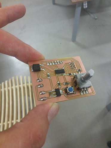
For this week I wanted to make a board with as much input devices as possible and compare them with each other, and I did the board but...designing a board and programming it wasn't as easy as I thought.
I made the first board considering it would have a motor for next week's assignment "outputs" and a lot of inputs, it had a potentiometer, a microphone, two buttons and an ultrasonic sensor, it was powered by a 12v DC source for the motor, and then with a voltage regulator lowered to 5V for everything else.
As you may encounter while making PCBs in Eagle, there are not allways the components you want, there are two things you can do, find a library online that has your component or design the component yourself, that's what I did with the superficial potentiometer.
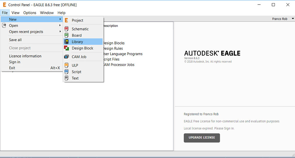
First enter to the control panel in Eagle, click on "file", "new", "library".
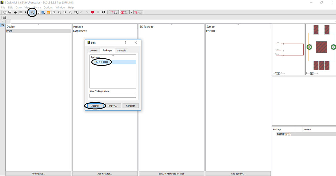
You'll be redirected to the following page, there you can start by clicking on "pacage" button shown in the image below, a pup-up window will appear, write your package's name and click "ok".
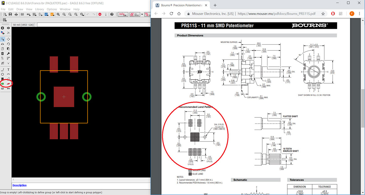
As soon as you click "ok" a black background page will appear, this is the sketch page for your component, I used only the marked tools to draw the potentiometer, I based the sketch from the datasheet on the right, here is the link to that datasheet: https://www.mouser.mx/pdfdocs/Bourns_PRS11S.pdf, save your package and go back to the table of content, this package is what you will be using when designing your board it is literally the surface of copper you will be soldering on.
Make sure you name each pad that is going to have a conection.
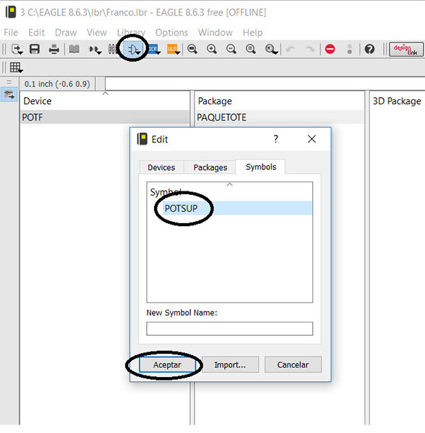
Click on "symbol" wich is the button shown in the image below, write your symbol's name and click "ok".
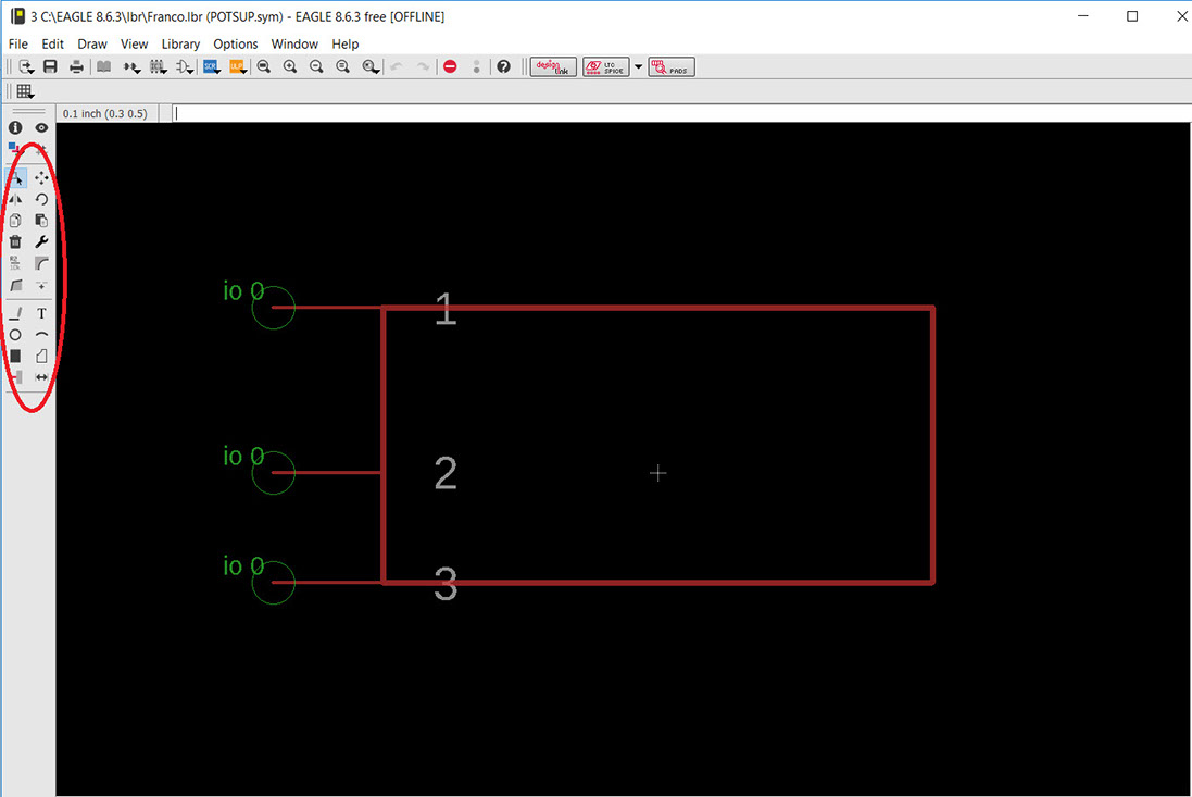
You'll be redirected to another black background page, this page is for drawing the device that you will be using when designing your schematic, as I will only be using 3 of the 5 pins of the potentiometer I only have to draw 3 pins, use the tools palette to draw your device.
Here you also have to name each pin with a name.
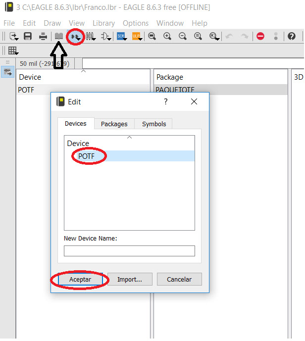
To go to "table of content" click on the oppened book as it is shown with the black arrow on the image below, then click on "device", it's right next to the table of content button, write your device name and click on "ok".
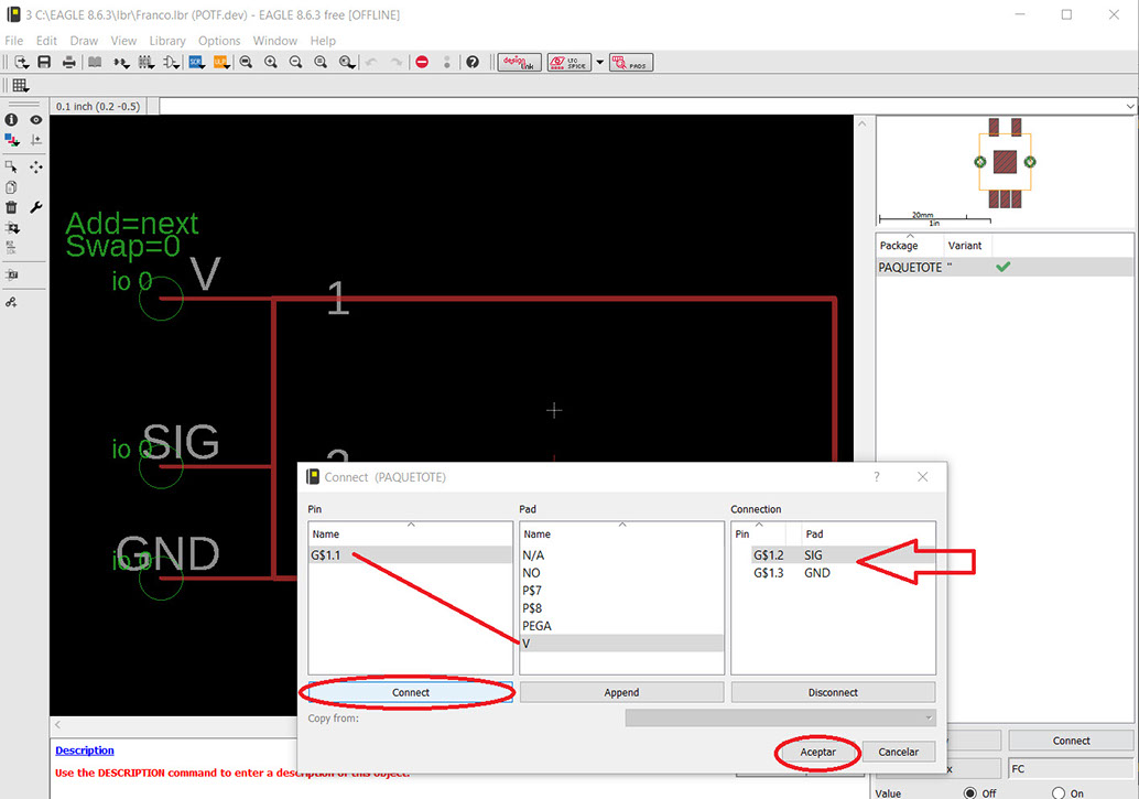
Here you have to make the conections between your pads and your pins, click the "connect" button on the lower-right corner of the page, the following window will appear, you have to select your pins and pads, click on "connect", the connection will appear where the red arrow is pointing, click on "ok" when you're done.
Save your new component and it will be available the next time you open Eagle.
To make your schematic simply click on the "add" button, search for your library and find your component, click on "ok", then just drag the component and start conecting everything together.
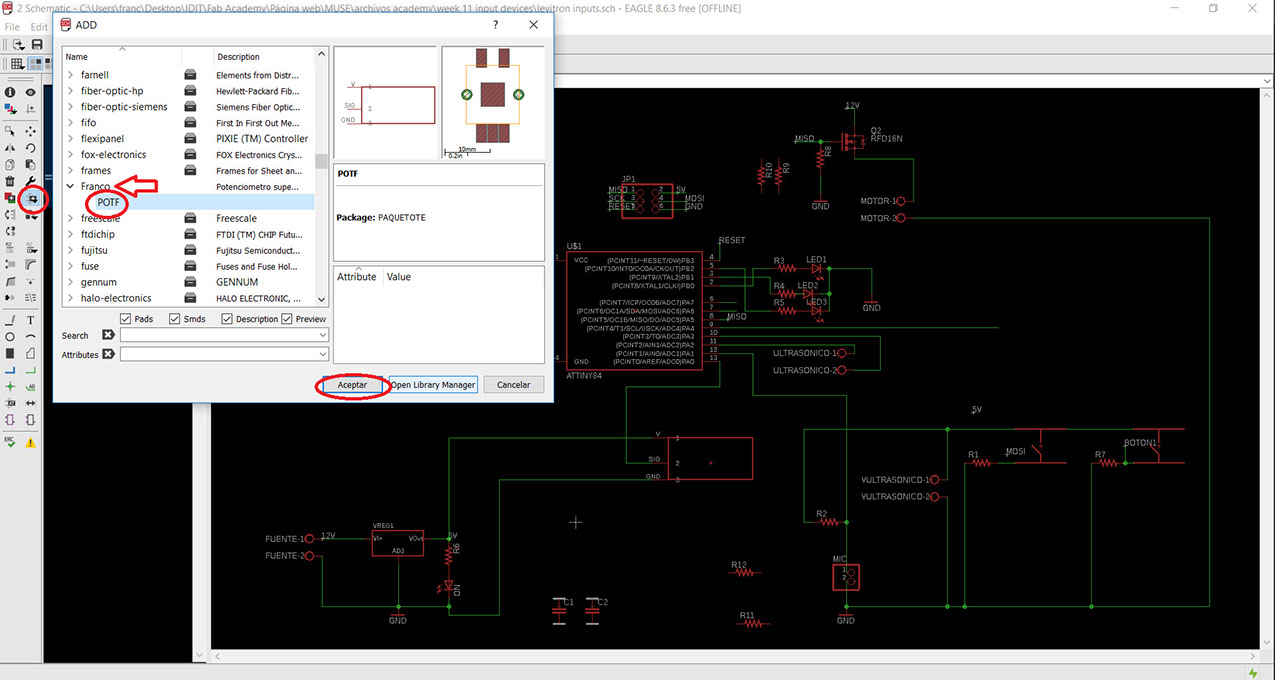
The board turned out like this after connecting every component and running the error tool.
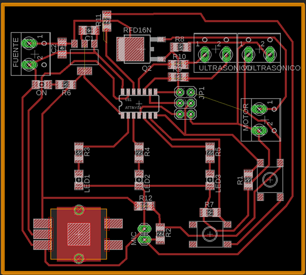
I got overconfident with this board so a lot went wrong, first I still dont know why the voltage regulator wouldn't work, then my mosfet was positioned wrong, so it wouldn't work properly, I was missing a conection from 5V to all my inputs (I could fix this with a wire) but I couldn't make the microphone work and didn't even got the chance to test the ultrasonic sensor.
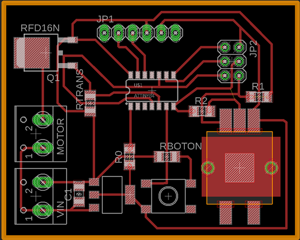
I couldn't fix this board and I lost a week so I designed a new one but simpler and with less inputs.


As I was getting behind with my board I took the chance to get ahead and made some pins to connect a bluetooth device for week 13 "interface and application programming".
As you would expect I also got this board wrong, I was missing a capacitor from the output of my voltage regulator.
It took me a lot more time than I am proud to admit to notice the capacitor, so I soldered a ceramic capacitor from the voltage regulator to ground and then everything went right.
For this board I just got a potentiometer and a button.
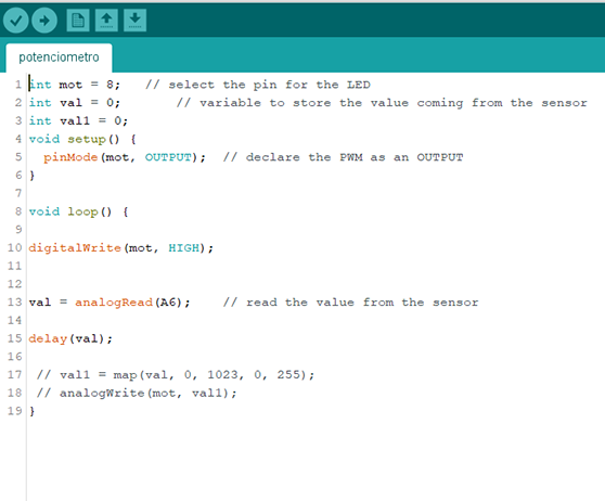
In this program I use the value of the potentiometer wich is from 0 to 1024 and put it direcly to de value of the delay, so basicly I am making a manual PWM by alternating the size of the delay between pulses.
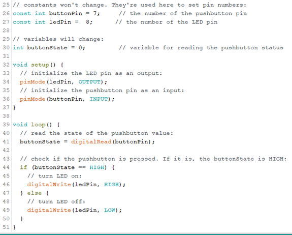
In this program I use example button and chenge the pins so the button pin goes to my button and the led pin goes to the transistor which turns the motor on.