Assignment 8
7.3.2018
Topic: Computer-controlled machining
Goals of this week:
- Make something BIG (individual)
- Test runout, alignment, speeds, feeds, and toolpaths for your machine (Group) (LINK)
Deciding the "BIG" project
Day before this weeks lecture was given, I found out about Wyrmwood´s Magnetic Gamemaster Screen Kickstart project. For those of you
who don´t know what the gamemaster screen is, it is a piece of bended paper or plastic which contains a collection of rules and other
important information which the gamemaster uses during the tabletop roleplaying game session. Addition to this, the game master screen helps
the gamemaster to hide confidental information from the players.
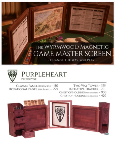
Wyrmwood´s game master screen is a modular product made out from wood which can be modified according to game master´s needs. It´s a great
product for a tabletop roleplaying game fanatics and a fantastic project for me to do for this week´s assigment.
Top: Commercial picture, Bellow: Pricing example for "Purpleheart" version in dollars (they are pretty expensive to buy).
Due to time limit of this week, I decided only to create 3 modular gamemaster screen panels as seen bellow:
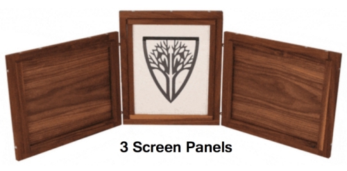
These panels have following functions:
- Embended magnets on every side so that the screens can be attached together in many ways
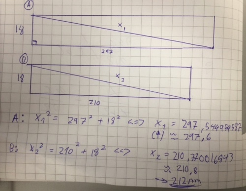
- Holder pieces and magnetic slides to hold A4 papers and projector slides (210x297mm)
- Holes and screws for turnable middle piece design
From designing perspective, my screen should also be:
- Lightweight (Minimum thickness and size)
- Durable (Strong magnet connections and good overall ballance)
According to these functions and designing requirements. I created following sketches. (Left: brainstorming, Right: exact measurements of the panels.)
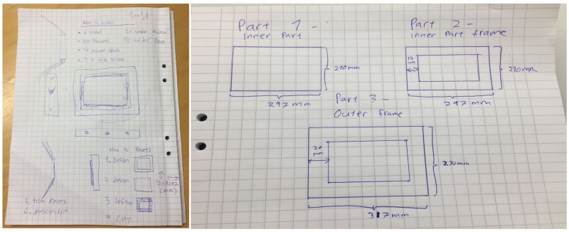
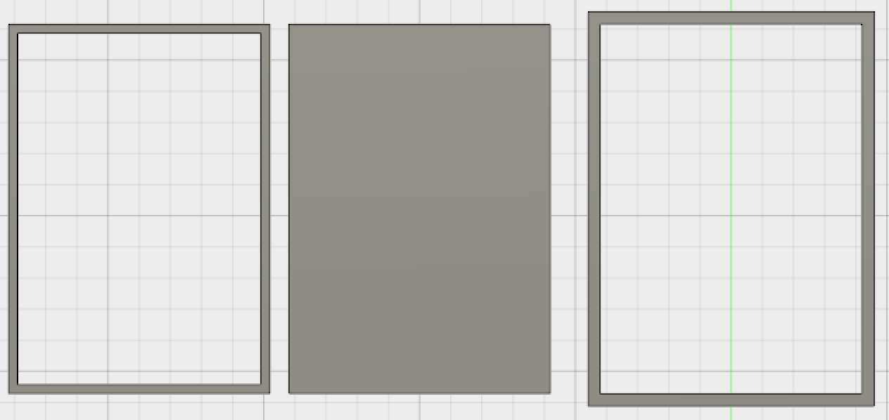
These sketches revealed that I had to cut following 4 pieces to conctruct my panels:
- Inner part (To hold paper)
- 2x Inner part frames (to hold paper on both sides of the design)
- Outer frame (To hold and turn the inner part)
I planned that when these parts are cut, I drill holes for screws from the outer frame to the inner part to be able to form rotating
gamemaster panel. I also need to either attach or embend magnets on the sides of the panels.
Before starting the designing process, I decided to use magnets seen bellow on the left and the material seen bellow on the right. The material was
chosen because it was the material which our lab had reserved for this week´s assigment.
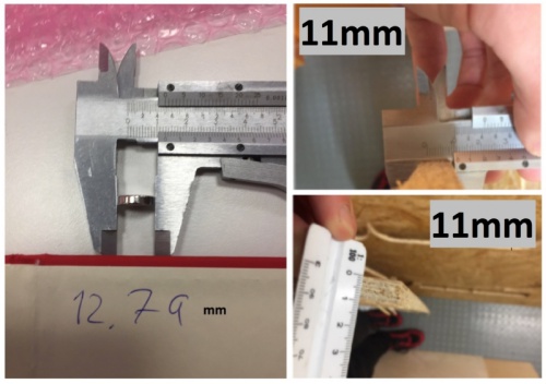
(Later, I decided to use magnetic tape instead of the magnets I mentioned and change the material for real wood.)
3d modelling the screen
I started 3d modelling by viewing good tutorial about CAM for CNC in fusion 360:
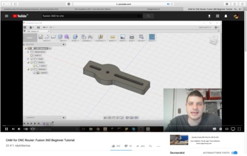
Then I began to model the frames, however, I got stuck when I tried to handle my frames as individual components. I had accidentally designed
them to be one body instead of multiple bodies:

To solve this proble situation, I watched following tutorial to learn how to convert
individual bodies to converters:
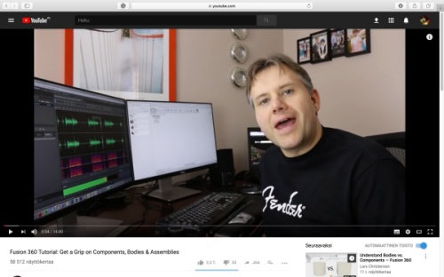
With a knowledge I got from the tutorial, I created each part as an individual bodies in seperate files by using measurements defined previously:

Then I created components from each of these bodies by chosing the body and chosing following option:
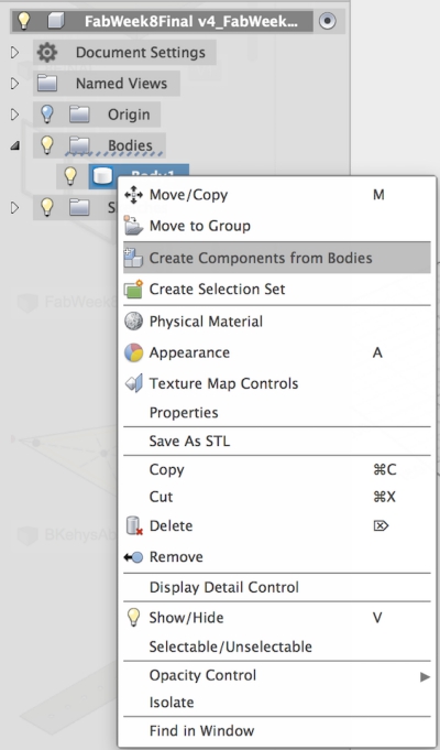
>
Finally, I mported all off them to one project file by chosing all the designs and clicking "Insert into current design" as seen bellow:
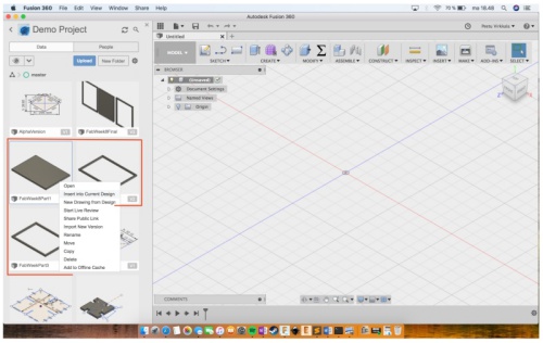
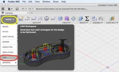
When I had all the parts together as components, I oppened CAM from Fusion 360 and started to
configure the cutting settings:
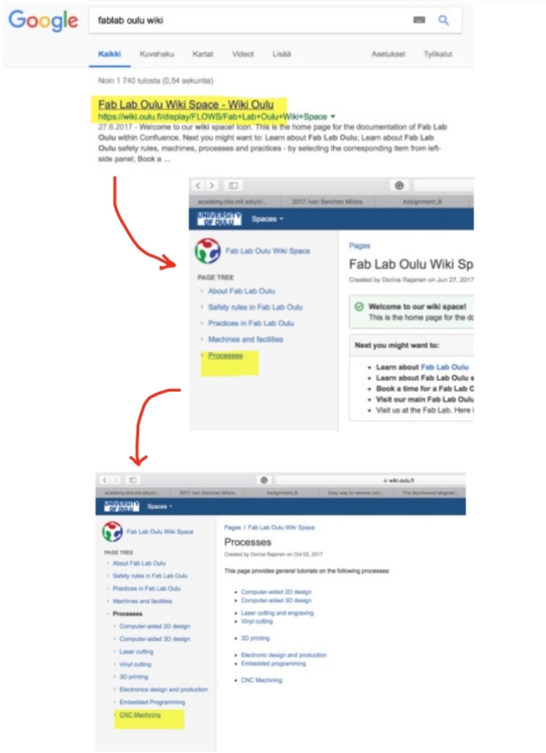
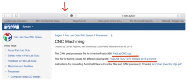
Megumi helped me to use CAMS. First, I downloaded Fab Lab Oulu tool library and CAM
postprocessor files from
Fab Lab Oulu wiki page
Then, I processed according to tutorial video and used specific cutting values for fabLab Oulu machine. First I went to Manage
> Tool library and selected Local and right clicked > Import tool library
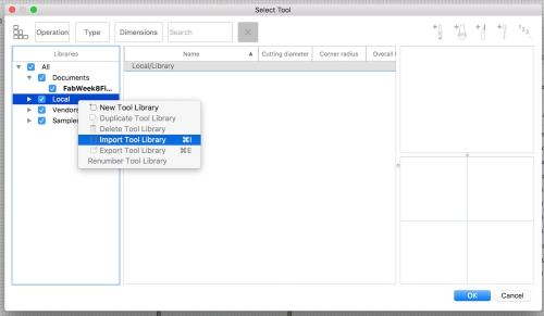
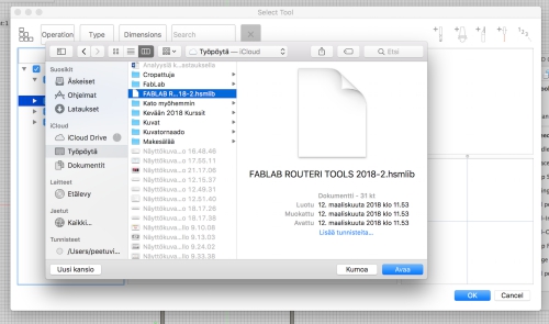
Then I chosed the tool library I downloaded and clicked ok
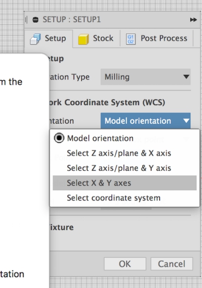
I clicked Setup > New setup. Then I selected Orientation > X and Y axes, Origin > stock box point and chosed the lower left
bottom corner on the top of the stock as a origin:
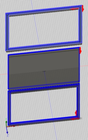
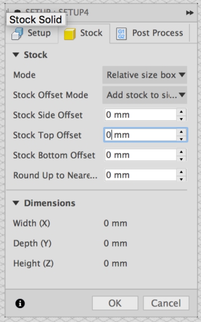
I went to Stock section and changed stock offsets to 0 and clicked "OK":
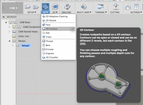
Next I began to prepare tool paths for cutting. To do this, I went to CAM mode with the model and clicked 2D> 2D contour
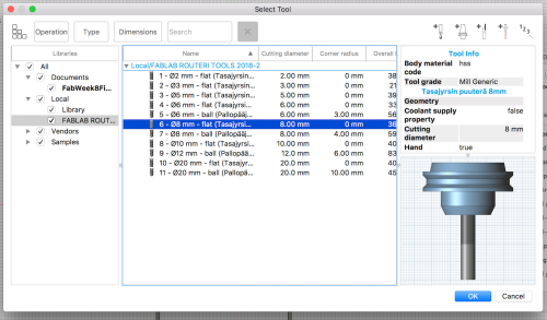
Tool window is opened, I clicked tool and chosed FabLab tool library which I dowloaded. From there, I chosed 8mm flat bit:
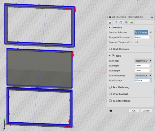
In Geometry tab I chosed inner and outer frames one by one in contour selection and created tabs as seen bellow:
In Clearance tab I chosed top of my frames as an top and bottom of my frames as an bottom. The depth was correct.
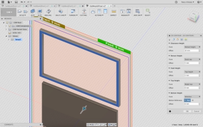
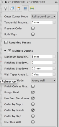
In Contour tab, I marked even stepdowns and used otherwise normal settings.
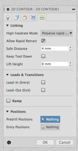
Finally in Linking tab, I used 4mm safe distance and unmarked Lead-in Entry and Exit.
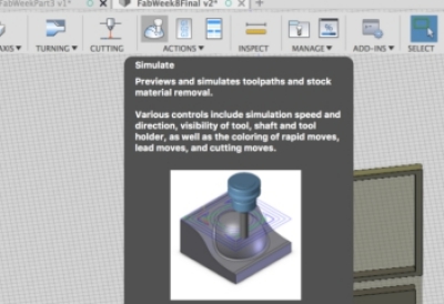
Finally before creating .nc file, I simulated my job to see that everything was going according to my plans by clicking Simulation icon as seen bellow:
Simulation went fine so I created .nc file by going to post-processing.
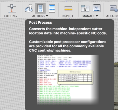
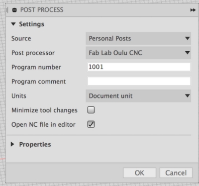
I choosed personal posts, FabLabCNC.cps as post processor and saved the file.
Cutting
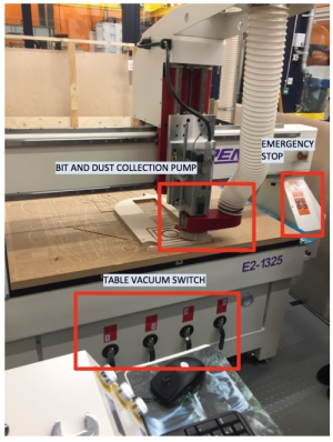
Our lab has Rensi E2-1234 CNC router:
It´s controlled by using control station:
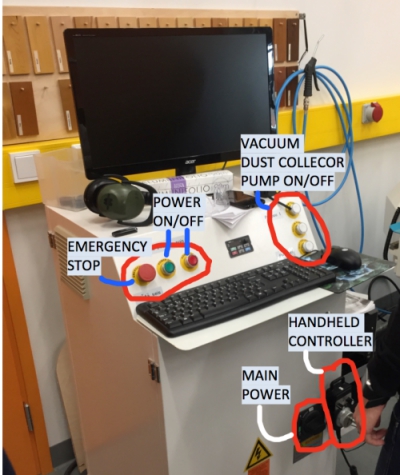
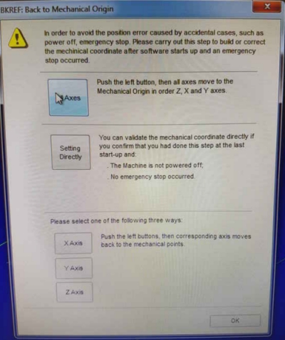
When the machine is turned on, open the NcStudion. When the pop-up window appears, press "All Axes" button to move all axes to the
mechanical origin or machine zero. When the machine stops moving. Press ok.
After this, I continued by attaching my milling material on the table with screws and ensured that the 8mm flat millin pit
was in use. I powered the computer by turnin main power switch on on the control station. Then I put my .nc
file in a usb-drive to CNC machine computer and .
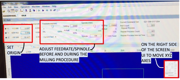
First I defined the origin point I moved the router with XYZ arrows on the screen to XY origin point which I wanted to use.
Then I used XYZ arrows to move Z axis to the origin spot where the drill was slightly touching the material. Next I clicked
set origin bars for X, Y and Z to set the origin. When this was done, I rised the Z axis little so that when the CNC starts
to mill, it doesn´t hit the material.
I cleared all the previous milling processes by right clicking the blue area of the screen and clicking "clear". Then I loaded my
file to the progam by clicking File > "Open and load". As in Fusion 360, I tested simulation to see how my design would be cut. I
was ok with the result, so I turned vacuum pump and dust collection buttons on on the control station. For my starting settings, I
used Feedrate value 80% and spindle value 70% which were basic values used in our lab for the material. If the machine starts to vibrate
or give loud sounds during the milling procedure, these settings should be changed during the milling. Otherwise the drill or other mechanical
parts may broke (too small feedrate/spindle value), or the material may be cut incorrectly (too big feedrate/spindle value).
My milling was ready to start. I clicked start button to began the milling procedure:

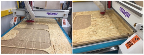
I had to stop the cutting process when the drill started to mill the outer frame. The drill milled the outer side first, which
made the material lose, and then tried to mill inner frame, which got the material stuck on the drill. Reason for this
strange milling behavior was probably my milling settings in Fusion 360: I had accidentally ordered milling order for inner
and outer part of the outer frame wrong way.
To rise from this failure, I opened outer frame design in Fusion 360 and made similar cutting settings for it as fo the inner
frame. Then I cut the outer frame again. This time, the outer frame was cut in right order.
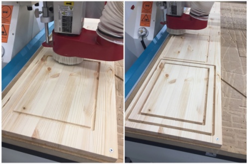
The milling was now ready
Preparing the design
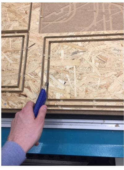
First, I used carpet knife to remove the tabs around my parts:
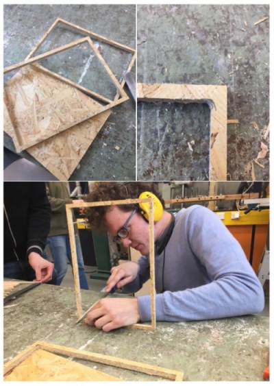
Because the drill is circle shaped, it left circled corners to inner corners of the frames. I used woodfile to square them
and to smooth the edges:
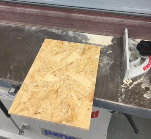
I had problems to fit inner part inside outer frame so I used sandpaper machine to shrink the inner part little bit:
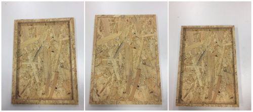
After preparing all 3 frame pieces as seen above, my first prototype frame was ready!
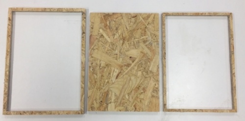
Here you can see inner frame/inner part, outer frame/inner part and inner frame/ inner part combos:
Assembling and testing the design
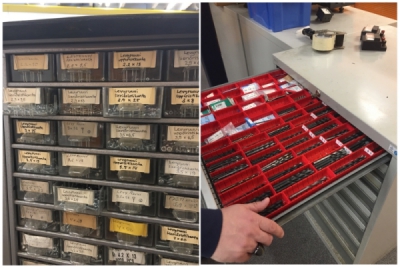
To create rotating frame, I had to drill two screw through the outer frame to inner part. First I went to screw storage
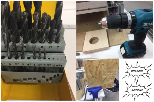
and picked the screws. Then I picked corresponding drilling end for the drilling machine.
Then I drilled holes for the screws by using a vise:
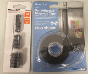
Next I began to think how the inner frame would be attached with the magnets to the inner part. However, I found
out that magnetic tape exsists so I decided to try it first instead of the magnets. I went to store and bought
roll of magnetic tape:
Then I found out that I didn´t actually need the inner frame and could attach the paper to inner part just by using
transparency with magnetic tape.
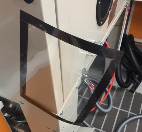
Therefore, I decided to use magnetic tape. I attached it to the inner part and to the transparency:
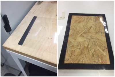
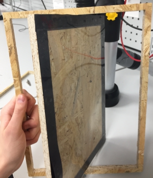
Screwed end result worked but it was not turning symmetrically and got stuck sometimes due to that.
Next it was create second version of the frame.
Creating the final frame
I wanted to use better wood so I went to hardware store and bought the birch board:
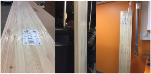
Then I used the same process for the milling but cut only the outher frame and the inner part:

Next I prepared the design as before and measured the calculated places for the screws...
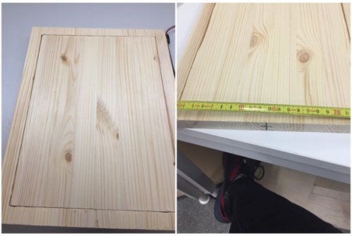
...and screwed the holes as before:
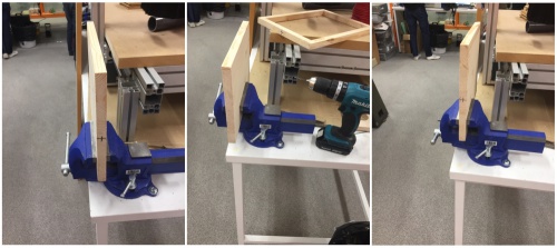
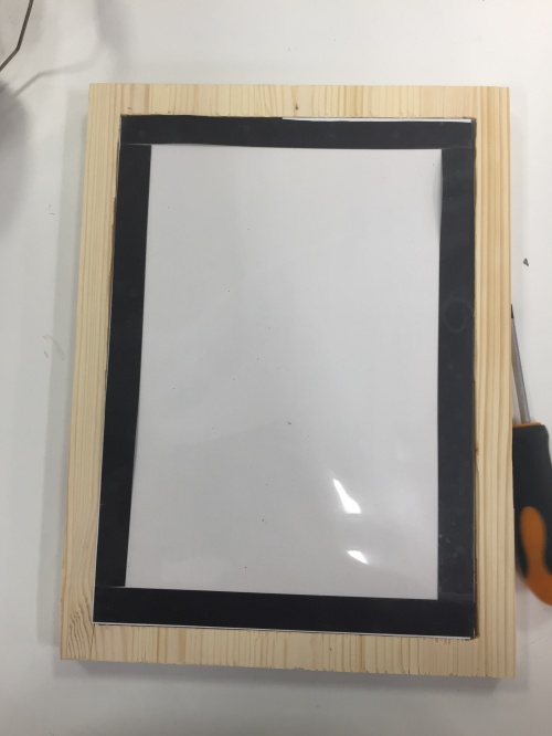
Then I attached the magnetic tape and my frame was ready:
For this week, I didn´t have time to create more of these frames. However, I identified few steps to develop
the frame further:
- Create holes for the screws with automatic machine, not by hand to keep symmetry
- Miter the edges and use plate and ball magnets to attach multiple frames in prefered angle
- Create visual engravings for the frames and stylish them
- Postprocess the frames for example by varnishing them
In future, I would want to build all the units of the magnetic gamemaster screen. This project could be one option
for my final project.
Group assigment: test runout, alignment, speeds, feeds, and toolpaths for your machine
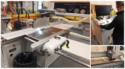
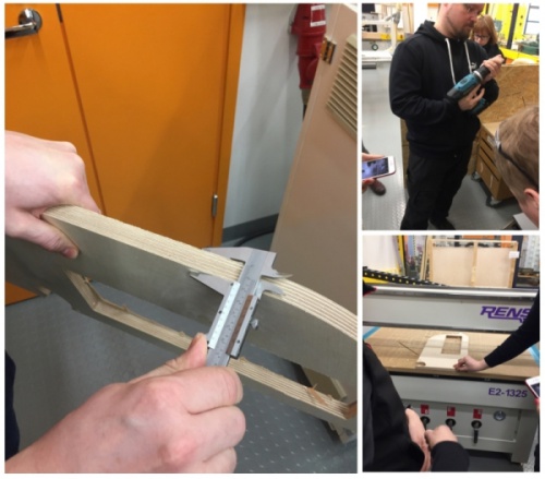
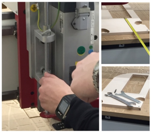
We finished the group work before individual assigments to get to know the CNC machine and the process. First, we designed
a simple part with Fusion 360. When the part was ready, we milled it from the board with the machine:
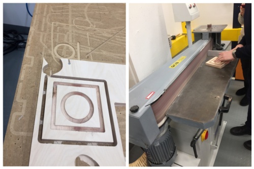
When the part was ready, we used sandpaper machine to do finishing:
FILES made THIS WEEK

This work is licensed under a Creative Commons Attribution 4.0 International License.


