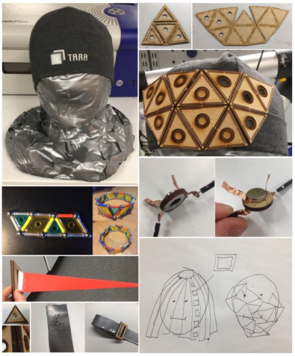
Overview (Click headlines to jump to topic, click "go up" to come back to top)
SYNOPSYS
What is it?, Status, How I´m aiming to create it?, Applications and implications, Invention, intellectual property and income
FRAME
6.5 Thinking about the size of the frame, 9.5 First big frame triangle prototype, 1.6 First version of the frame, 7.6 Creating frames for the frame, 12.6 Finishing stickers and adding washers
11.5 Cutting settings, copper sticker and triangle chain, 14.5 Sewing connections and frames, 18.5 Testing different materials
22.5 Birchbark test and first bigger assembling, 29.5 Second bigger assembling, 30.5 Third bigger assembling
MODULAR PIECES
4.5 Designing the frame part locking system, 21.5 Embroidery design, 24.5 3D printed connector piece,12.6 Testing the frame locking system, 14.6 Designing and printing paper parts, 15.6 Laser cutting designed paper parts, 17.6 Making part from rice paper, 16.6 Building paper parts by hand and 3d printing final connector pieces
INNER PART
1.5 Fastening strip, 14.5 3d printing connecting strip
ELECTRONICS
11.5 Thinking about the wiring, 31.5 Megumi´s neopixels, 14.6 Thinking about the package of the board, 15.6 Building a battery holder and testing the package, 16.6 Packaging new version of the board, 17.6 Developing the package and boards, 18.6 Prototyping two sided board, 19.6 Finishing the boards, 20.6 Finishing the software
VISUAL & OVERALL
27.4 Creation of the mannequin head, 28.5 Screenscrip for the video, 20.6 RESULTS
FINAL PROJECT (SLIDE) (VIDEO)
In Details
SYNOPSYS
What is my final project? (go up)
My final project is a fabricated helmet which enables user´s to construct modular shapes on the top of the helmet.
By doing this, users can create unique helmet designs for visual and artistic purposes. As a finishing touch, led´s
can be connected to these modular shapes and controlled by users. WEEK 1 decribes the concept in more detail
Status: (go up)
DONE Mannequin head, Fastening strip
UNDONE Frame part locking system, Frame fitting system, Modular pieces
How I´m aiming to create it? (go up)
In short: my creation process goes forward as follows:
Build the frame
Build the modular pieces
Create visual material
Expand the project if there is still time
Applications and implications (go up)
What will it do?
My final project, modular helmet creates a versatile building surface on the top of your head. This surface can be used to create unique designs on the top of your head by using different kind of materials and electronics. With theses designs, users can act as different characters.
The helmet consist of modular MDF structures that are bonded together so that the helmet adapts to user´s head so that it can be taken off and put on the head with ease. Modular pieces are made by the user according to his or her´s needs and attached to helmet either directly or by using 3d printed frame-modular piece connectors. Connection between modular pieces and the helmet is achieved by connecting strong ferromagnets in modular pieces to metal washers inside the helmet. Because of this, modular pieces can be attached and unattached easily. Even so, the magnetic bond between the ferromagnet and metallic washer is capable of holding the weight and shape of even more heavier and complex materials like metal and wood.
Electronics of the helmet include a mainboard, a lightsensor board and an individual LED boards which are powered by two 3V button batteries. The lightsensor board measures chages in the room lighting, mainboard gets this information and controls the brightness and On/Off situation of individual LED´s. Goal of this electronic system is to illuminate helmet in dark environment to higlight existing details like shapes of modular pieces and create new visual elements like fast light patterns.
Who's done what beforehand?
There are multiple Fabacademy students that have created different kind of helmets before me. As a final project, Jasmin Rubinovitz created bike helmet by using composites whereas there are multiple tutorials online which teach how to build led interface for motorcycle helmet motorcycle helmet. Hovewer, I didn´t found modular helmet designs that connect both electronics and modular design.
My modular helmet is made of the modular pieces, the frame and of the inner part. For the frame, I have got lot of ideas from Yogi Kulkarni´s laser engraving assigment. He created a geodecim by using the laser cutter. I´m also using the laser cutter for similar kind of shape, so I used the geodecim calculators which he mentions on his page.
What will you design?
I will design the following things:
- Modular frame pieces
- Instructions to assemble modular pieces
- 3d printed modular-frame connector pieces
- Frame attachment solution for the inner part of the helmet
- Head attachment strip for the helmet
- Electronic board system to change the status of the LEDs according to the data got from the light sensor
- Board controlling interface
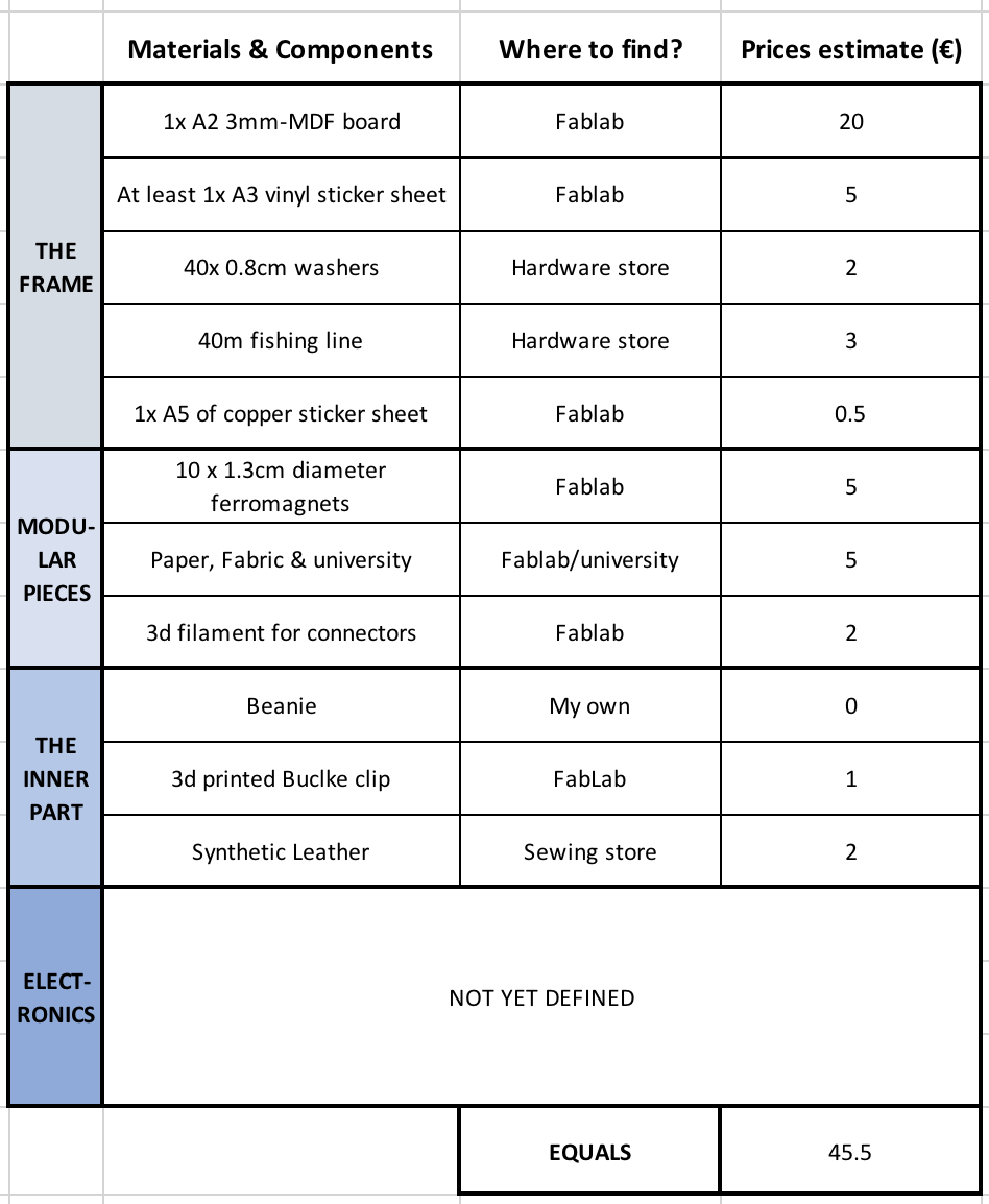
What materials and components will be used/ Where will they come from/ How much will they cost?
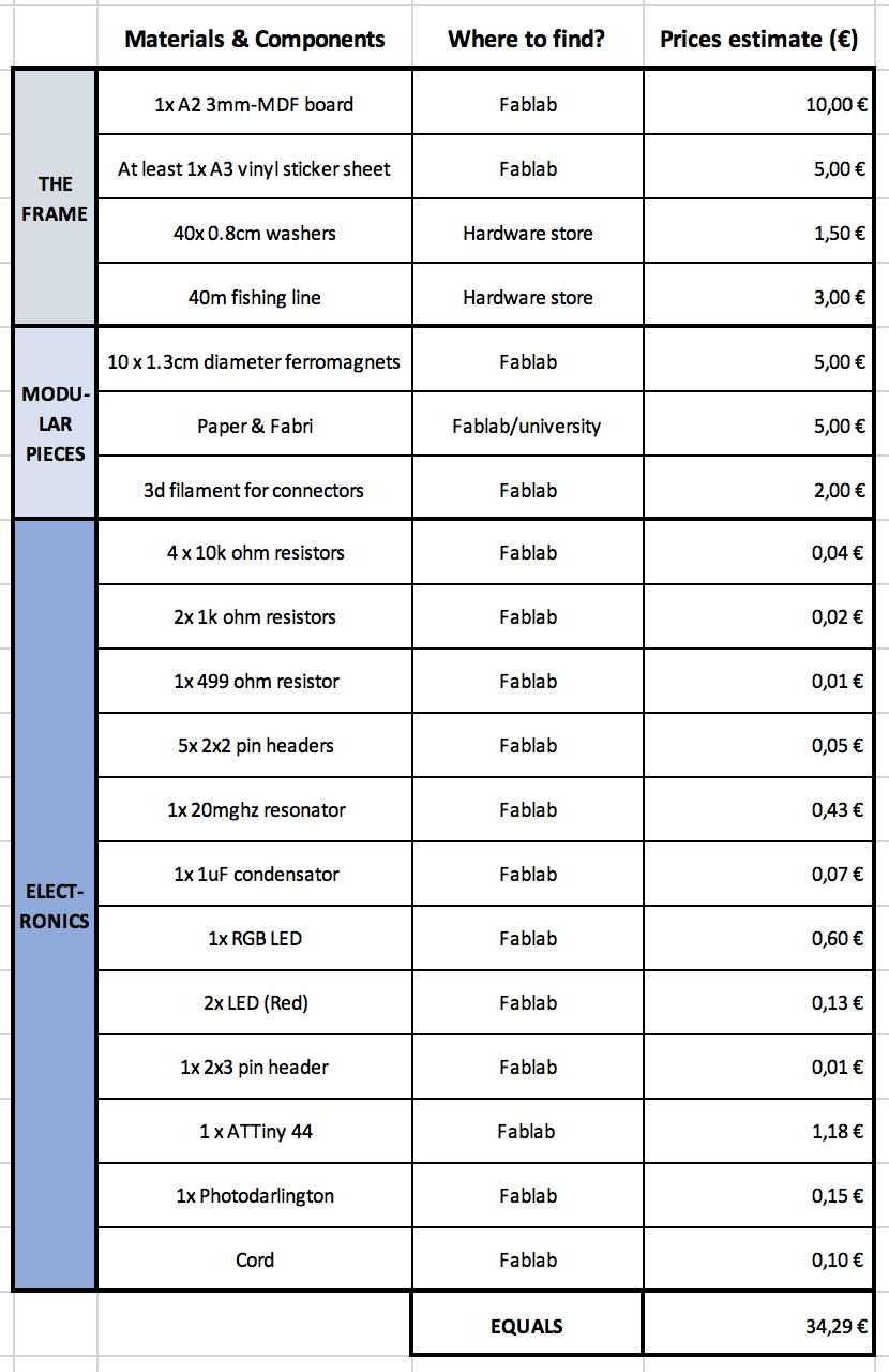
I listed my assumptions to following excel-template:
What parts and systems will be made?
The following parts will be made:
- Modular pieces from paper, fabric, and other materials like wood
- Modular-frame connector piece
- Electronic holders
- Frame made of modular triangle geodecim pieces
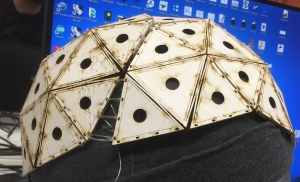
- Inner part of the helmet
The following systems will be made:
- Mainboard-ledBoards-LightSensor board system
What processes will be used?
Following processes will be used:
- Laser cutting = subtractive process: Creation of the frame pieces and frame parts for the frame pieces
- 3d printing = additive process: Creation of the modular-frame connector pieces
- Embroidering= additive process: Creation of few modular designs
- Board milling = Electronic production: Milling of the board system boards
- Embedded programming (C, Arduino)
- Input device: Light sensor
- Output devices: LEDs
What questions need to be answered?
How to connect modular frame parts together succesfully?
How to attach the frame to inner part of the helmet?
How to control LED´s?
How to achieve firm bond between the frame and modular pieces?
How to attach electronics?
How will it be evaluated?
My project will succeed if:
- The helmet can be put on and taken off from my head -> The structure is able to bend
- The helmet stays well on top of my head -> The frame is secured to inner part which is secured to my head
- Modular pieces can be created, connected and removed succesfully -> At least 10 modular pieces can be connected together to form the frame
- Input from light sensor is capable of changing the status of the LED´s -> The boards work and they are able to send eligible data to each other
What questions need to be answered?
- Is the helmet durable enough according to the current plan? If not, how to make it more durable?
- How the modular pieces could be designed on the top of 3d head model to enavble better fit?
- Could the helmet be build from the press-fit-kit? If could, how the helmet could be packed and sold for the customer?
What tasks need to be completed?
The following tasks should be completed:
- Design and build a durable frame that fits your head
- Design and build different modular designs and connector pieces that can be used to attach designs to the frame
- Design and build the inner part that is connected to the frame and to my head firmly
- Design and build electric board-system that works according to requirements
- Design and build system that attaches electric board system to the frame
- Document and visualize the helmet
What is the schedule
From the 27.5 to 20.6 the schedule is as follows:
28.5-3.6 Focus on finishing the documentation of week projects. When some extra time, develop the frame further
4.6-10.6 Finish the documentation and finish the frame and the method to connect modular pieces
11.6-17.6 Finish the electronics, inner part attachment system and documenting
17.6-20-6 Create presentation and visual material for the helmet.
In future: Develop the helmet design and technology forward for the own use and even for the commercial purposes
Invention, intellectual property and income (go up)
- Develop a plan for dissemination of your final project (Individual)
- Prepare a summary slide (presentation.png, 1280x1024) and video clip (presentation.mp4, 1080p HTML5, < ~minute, < ~10 MB)
in your root directory
Thinking about the legal and business future of the project
Intellectual property
To be able to develop my final project further after its completion, I spent part of this week by considering intellectual property rights.
What is my motivation behind the project
From the start, I have planned that my helmet is made to fulfill my personal needs. I like to act as a different fictional character - especially more mysterious and unreal characters. I prefer to create my own characters and act as them instead of acting as other characters. Therefore, I want to use my helmet as a prop to realize some of these characters visually and functionally in artist manner. Because this, I feel that there is a high possibility that I will develop and expand this project further in future.
Future opportunities and business opportunities
I believe that humans will begin to use more and more functional headpieces (masks, helmet, etc.) to exploit AI and IoT possibilities as a part of their daily lives. I feel that these headpieces will have also a fashion purpose which leads people to use them just even for their visual features. I think that headpieces which combine technology, modularity, and opportunity for self-expression in these times will be the winners of this market.
These beliefs reflect my final project, where I aim to design modular an functional smart helmet which users can use to express themselves. Currently, I feel that there lies a demand for a modular helmet making kit which customers can use to create unique helmet designs around their heads and modify them according to their needs to express themselves through the helmets with help of modular designs and embedded technologies like screens, LEDs and Arduino's.
There are multiple ways how these helmets could be sold, for example:
- Design and order model
Customers use their phones to create a 3D model of their head and upload it to helmet firm´s web page or app. From there, users could create or generate helmet frame that fits perfectly to their head. Then, the user could order these parts as a construction kit to their home or optionally as a full assembled helmet.
- Buy the basic kit, build your own
To easier the manufacturing, the helmet kit could be sold as a one standard package, that could still be used to create a frame for almost all different human head shapes. This could be achieved for example by using small triangles, which enables huge customizing possibilities.
- Build ready made helmet
Helmets are made as ready-made frames. The user can customize the helmet only through modular designs and embedded technologies.
Add-on-possibilities could be provided for example by:
- Sell Add-on possibilities to helmets
Provide a specific range of products like modular pieces and embedded technologies that can be added by the user to the helmet.
- Let users design their own add-ons
Design the helmet so that the users can create their own modular helmet pieces and embedded aspects and share them
Helmet could be manufactured for example by:
- Use Fablabs or Fablab-kind of producing spaces
- By subcontracting parts and/or assembling needed for example from China
From these, I feel that Design and order model, let users design their own add-ons, usage of Fablabs or Fablab-kind of producing spaces would be the best combination for the future. If I´m able to design this kind of helmet and/or helmet design software, I will consider taking it to market by creating a startup around it and by gathering investments through investors, funding, Kickstart and through other possibilities.
Licenses and sharing
Addition to future and business opportunities, I also considered different licensing possibilities. Many of the licenses listed on this week´s site are meant mainly for software purposes. For example, MIT license is a software license created at MIT. This license allows others to reuse licensed work with limited restriction which is that all of the licensed software have to include the MIT permission notice. Gnu general public licenses allow users to copy, distribute and modify the software as long as all the changes and dates in source files are tracked and as long as made modifications are available under the GNU GPL with appropriate install & build instructions.
However, currently, my project is mainly just a physical product with minimal software functionalities. FAB license could be used for my physical product to get my "project name" acknowledged and copyrights retained if my work is reused. However, I´m more interested about Creative Commons License Attribution 4.0, because it enables me to share my project for others to develop further when still getting a credit of my work if the project is developed further by someone else.
If my project would develop further and I would be able to make the helmet constructing kit that has business potential, I would consider other options. But for now, Creative Commons License Attribution 4.0 is enough for me.
OVERALL
27.4 Creation of the mannequin head (go up)
I wanted to have mannequin head similar to my own head to visualize physically how my helmet should look like and how it should attach
to my head.
After researching different possibilities, I came to a conclusion that I want the mannequin head to be an exact copy of my own head shape.
Most common examples to do this include creating silicon mold and scanning and 3d printing your head. However, our lab didn´t have
necessary molding materials and 3d printing my head in 1:1 scale would be extremely expensive so I decided to use cheap but fulfilling
alternative method: masking tape, plastic food wrapping, and a polyurethane seal.
For this method, I used the help of two of my friends. I sat in a chair and my friends wrapped plastic food wrapping all around my head and
neck except the mouth area because I had to be able to breathe somehow. Then, they wrapped masking tape around my head following the shape
of my head:
When the masking tape wrapping was ready, my friends cut the mask off my head and I taped my mouth area and the cut back together. I had now
masking tape frame of my head:
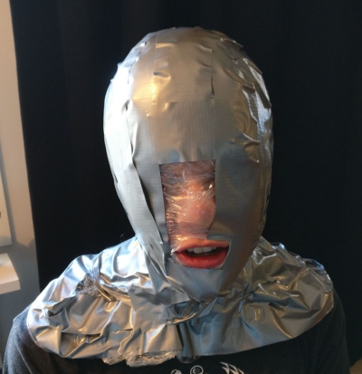
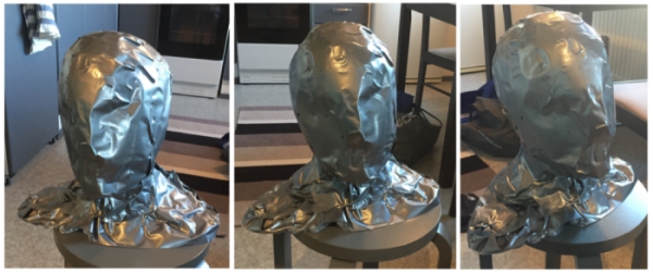
Next, I had to fill the frame. I went outdoors, put spine made of newspaper inside the frame and sprayed polyurethane seal into the frame.
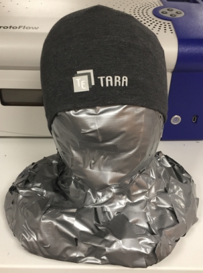
Then I left the polyurethane expand and harden for one day. When I came back, polyurethane had expanded and the frame had kept its shape.
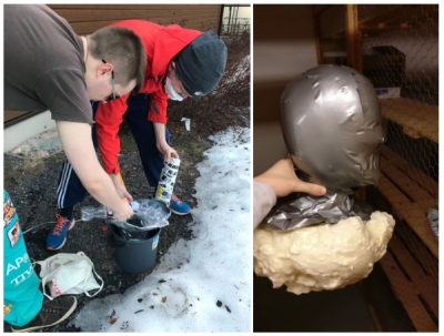
Finally, I took the frame to Fablab, cut extra polyurethane and sealed bottom of the frame with a masking tape. Mannequin head was now ready!
FRAME:
6.5 Thinking about the size of the frame (go up)
Before designing the frame pieces, I used geomags on top of the mannequin helmet to test different shapes around the head. This test revealed that triangle shape fitted well for my use and I decided to use it as a base shape.
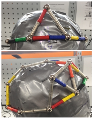
I also tried to use 3d head model stl model in Fusion 360 to design the frame around it. However, this was more complicated than I thought and I feeled more comfortable to design the frame to top of the real model. Therefore, I decided to give up 3D modelling and consentrate to physical modelling.
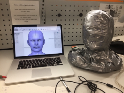
9.5 First big frame triangle prototype (go up)
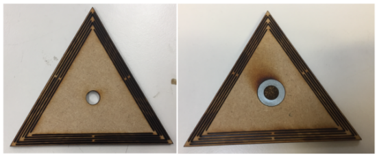
I wanted to build frame from bendable parts so I researched more about living hinges made around triangles. I found Obrary´s free living hinge designs. They had specific living hinge design designed to create bendable triangles:
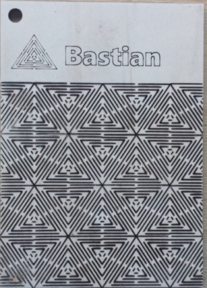
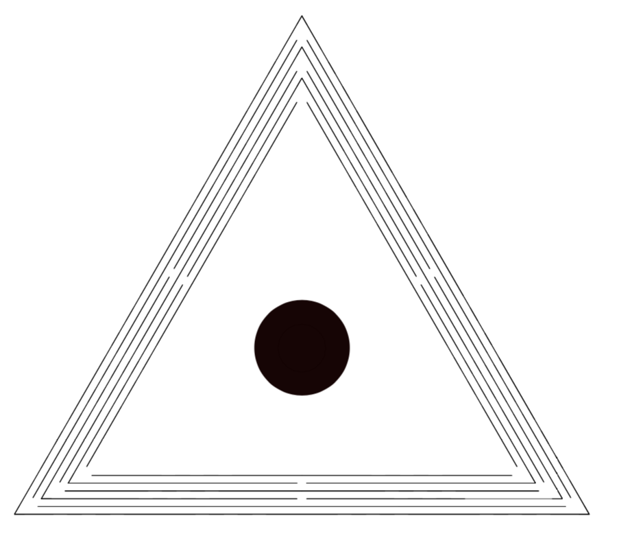
After inspecting the design, I created my own version of the design in Fusion 360 and edited it in Inkscape, I wasn´t sure if it would work.
However, when I lasercutted it, the design was working fine.
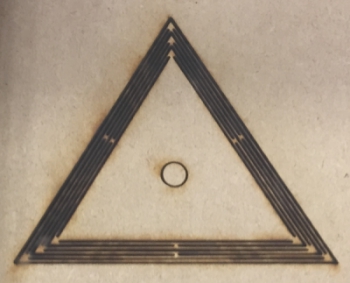
It could be bended from the sides and the living hinge structure was strong. I decided to use this design for my final project. I also made hole on to middle of the design for 8mm washer to attach ferromagnets later on. Next step was to decide the size of the triangle.
11.5 Cutting settings, copper sticker and triangle chain (go up)
As a next step of my frame piece designing, I designed two pieces connected together to ensure that bending frame pieces could be connected together.
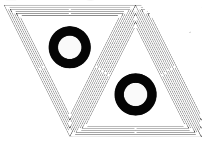
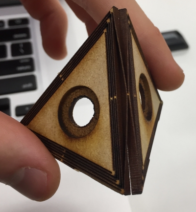
The design worked well and the pieces could be bended over 90 degrees:
Next I created chain of these triangles to see how they bend around the mannequin head:

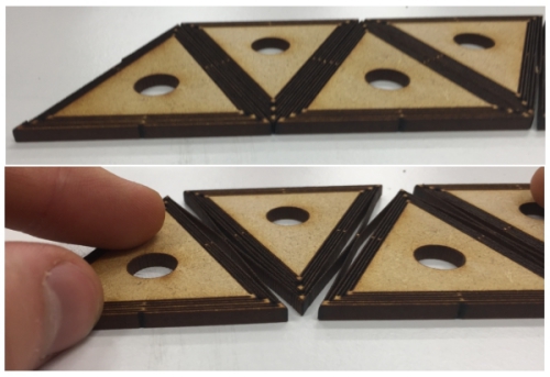
It bend well around the mannequin head:
I wasn´t happy with the mitters between the parts, therefore, I designed hexagons build from these triangles
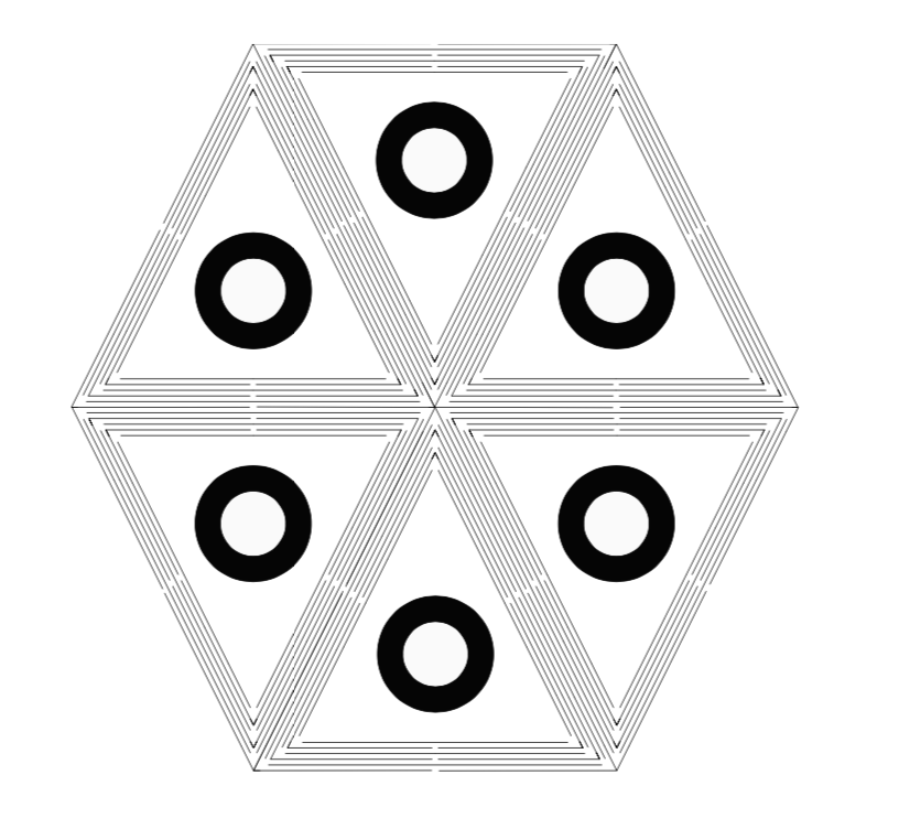
However, This time mitters at the middle of the pieces were still bad. Therefore I decided to design this triangular design further in future
I also decided the engraving parameters for the washer holder hole. First I designed hole for engraving and placed it at the middle of the triangle design:
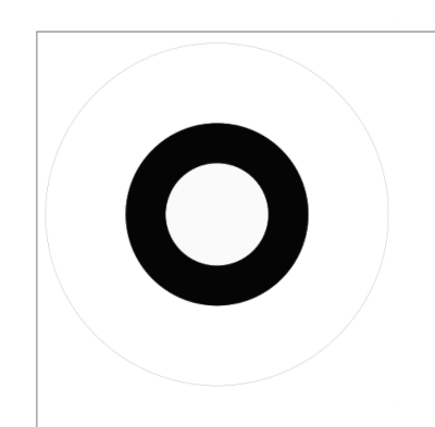
I tested different engraving settings for MDF and decided to use Normal mdf engraving settings (40%) and engrave the hole 4 times.
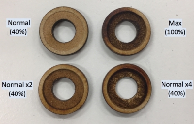
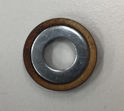
When the engraving was finished, I sandpapered it and attached the washer. The engraving was perfect and the washer could be stuck inside without the glue:
14.5 Creating frames, frame patterns and sewing holes (go up)
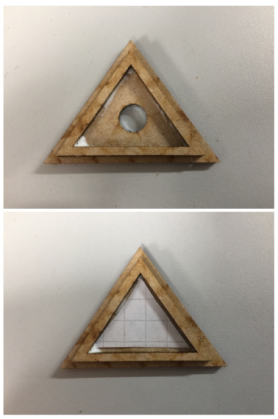
I created frame parts on the top of the triangle pieces to cover them with colorfull material when they are not in use. First proto can be seen below:
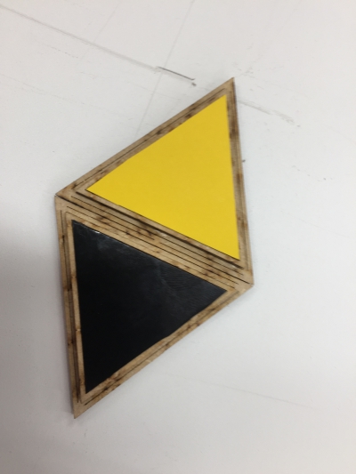
Frames with black and yellow vinyl stickers can be seen below. I liked the frame design and desided to use it:
Next I tested different frame part chains. Firts I created chain:
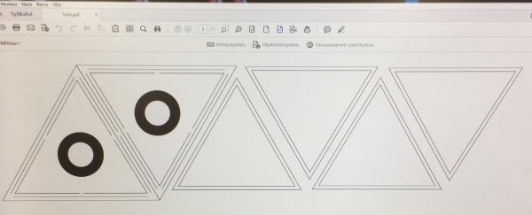

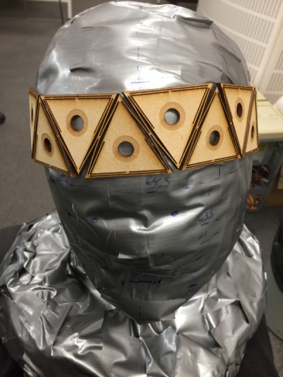
Then I created frame design by using two different kind of triangle sizes: 1 A triangle on the middle and 3 B triangle around:
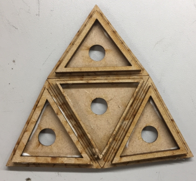
However, these triangles couldn´t be cut as a chain because their overall angle was over 360 degree as seen below:
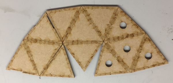
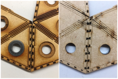
To add them toghether, I designed holes for sewing on the edges of the pieces:
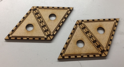
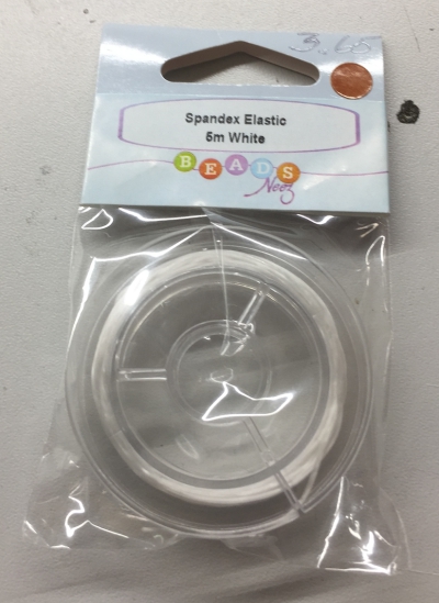
Then I used spandex cord to connect them together:
Even thou the sewing was time consuming, it worked well and I decided to use it as my method to connect the pieces together.
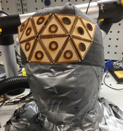
18.5 Sewing and testing different materials (go up)
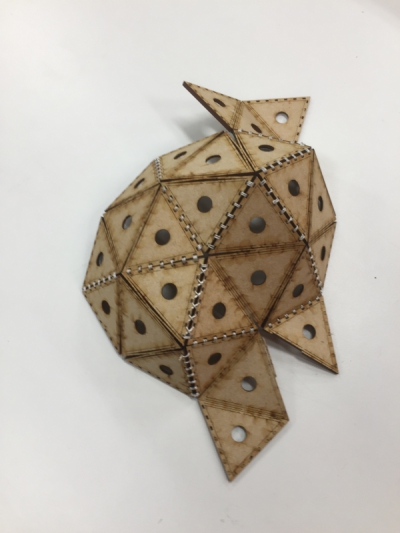
I sewed two frame parts together, the end result looked nice:
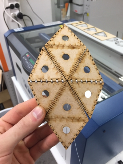
However, when I sewed multiple parts together, I run out of the spandex cord and the overall shape wasn´t symmetric. To fix this, I decided to use in future parts with fewer sewing holes and sew parts as two sewed part pieces (as seen above) to be able to connect the parts symmetrically together.
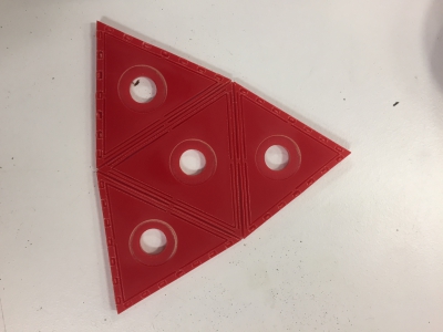
I didn´t liked that much of the color and the smell of MDF, so I tested different materials and finishin method for frame parts. I began by cutting acrylic piece. It was not flexible enough:
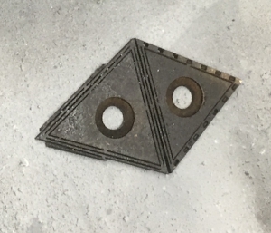
I sprayed MDF but the color and the smell was not good:
Finally, I glued paper on the top of MDF board...
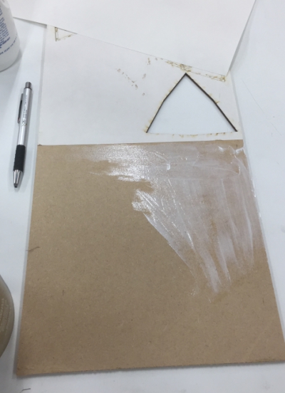
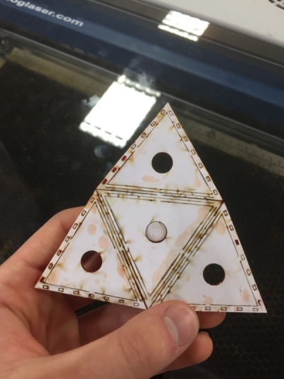
...and laser cut it. The end result looked good, little woody, and I decided to use it in my project.
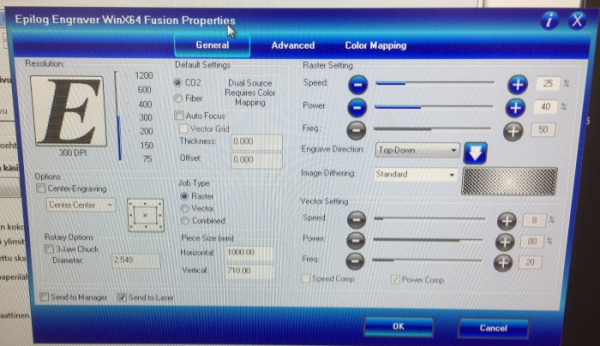
For this method, Following are the best cutting settings on bigger Epilog laser...
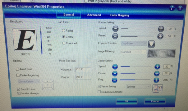
... and smaller Epilog laser:
22.5 Birchbark test and first bigger assembling (go up)
I made design with less sewing holes and used fishing line (right) instead of spandex (left):
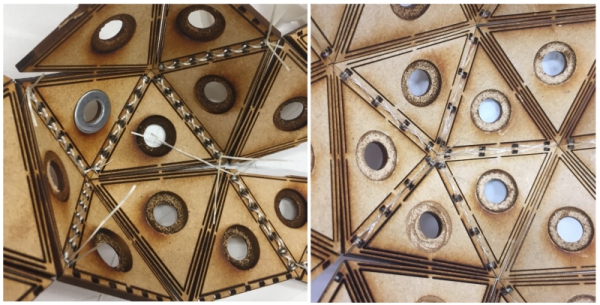
Then I sewed few bigger frame parts together...
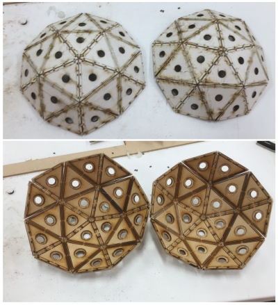
...and sewed them together, however, there were gaps when I put the helmet on the top of the mannequin head. Mannequin head was little bigger than my head and I had some errors in my sewings. I have to fix this in the future:
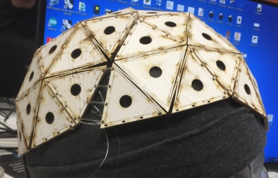
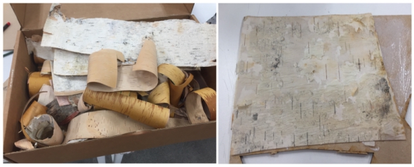
I also found out that we had birchwood bark in our lab. I decided to test it as a surface materia. I glued it on the MDF and handled the top part with the glue water.
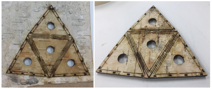
End result looked good. I´m planning to use birchwood in my future projects to get similar finishing touch to my projects:
30.5 Second bigger assembling (go up)
Instead of mannequin head, I tested to sew the frame parts together and put the resulting shape on the top of my head:
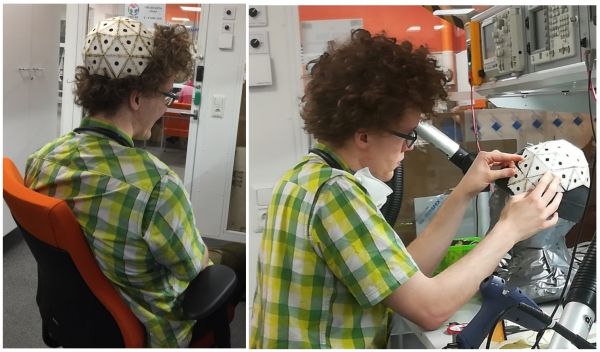
I found a method to connect the parts together so that I could fit the resulting shape on the top of the mannequin head. I decided to use this design:
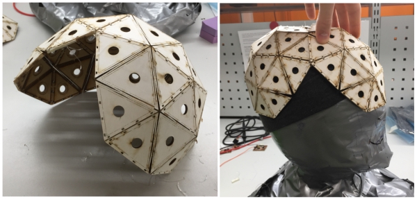
1.6 First version of the frame (go up)
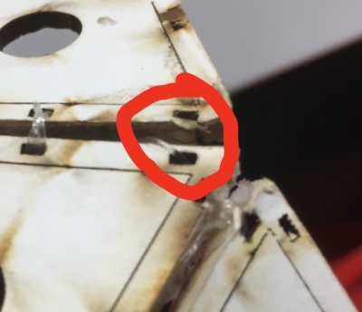
When I sewed the frames together, sometimes the sewing hole broke. I fixed this with a hot glue.
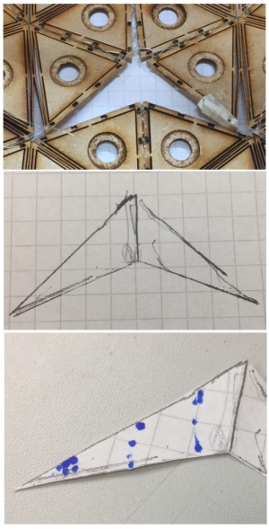
Due to the way which I connected frame parts together, there was a gap on the top middle point of the helmet:
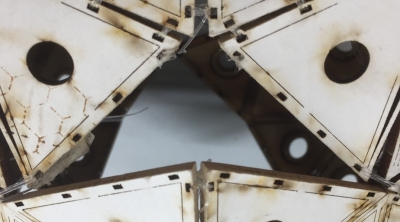
I began to fix it by drawing part that was size of the hole:
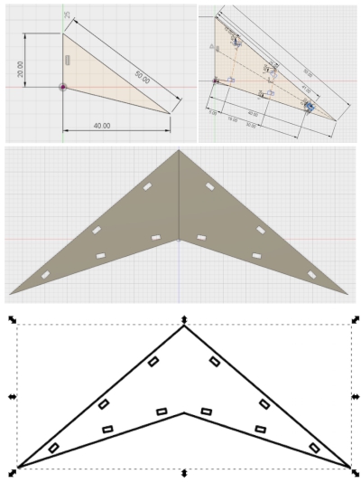
Then I measured the part and made it in Fusion 360:
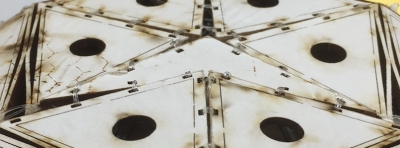
Finally I sewed it onto its place. It fitted well:
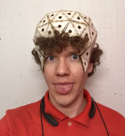
Even thou I want to make full head helmet, MVP of the helmet was now ready, and I decided to use it for my final project:

7.6 Creating frames for the frame (go up)
I build frame on top of the frame part
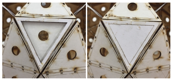
I prepared the part by sandpapering and gluing it
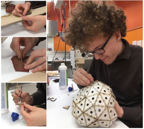
It looked good so I decided to fill whole helmet with it
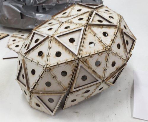
Sticker parts fitted well
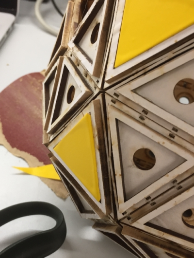
I filled all frames. It looked nice.
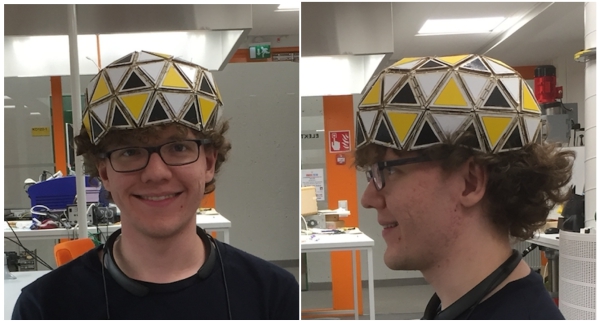
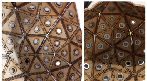
12.6 Finishing stickers and adding washers (go up)

I hotglued 8mm washers under the frame. Now I could attach parts with magnets to the frame:
MODULAR PIECES
4.5 Designing the frame part locking system (go up)
I used two laser cutted triangles to help me to visualize possible locking system. In the end, I decided to use paper as an outer parts material.
Locking system has to fulfill following requirements:
- User can fold and glue 3d paper form that can be attached to locking system
- Locking system is able to sustain weight of simple and more complex paper formations
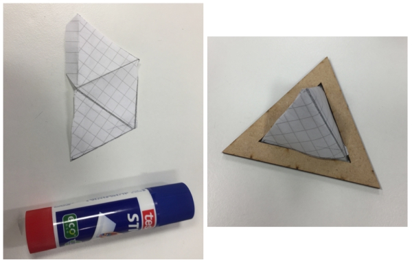
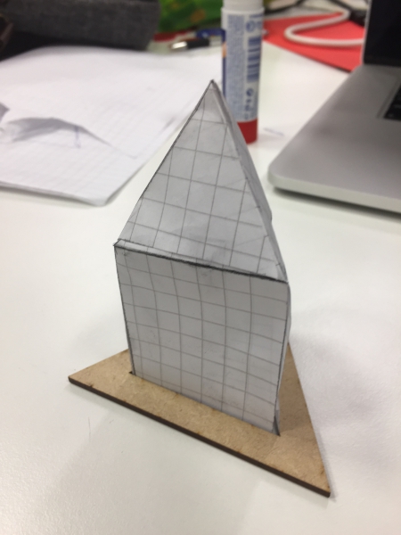
I got few different locking system ideas. First one was an idea to make thin gap where the paper would be pushed:
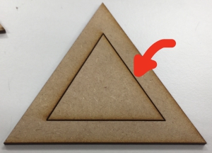
This idea was ineffective so I decided to try something else.
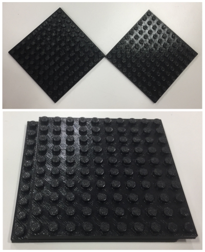
Next idea was to create some kind of locking parts like in lego´s by using 3d printing or molding:
To test this idea, I created parametric Lego-like block and 3d printed it:
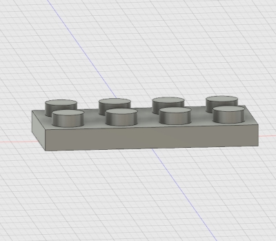
However, the 3d printing was not detailed enough, so I decided to test alternative solutions
Third idea was to use magnetic tape to attach paper and the frame together:
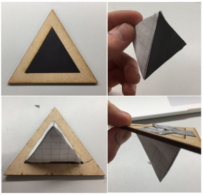
However, the connection was not durable when I attached more weight for the tape. I would need more powerfull magnetic tape:

Fourth and my chosen idea was to create connections by using stron ferromagnets and metal rings. Metal rings would be embedded
to triangle´s and ferromagnets would be attached to paper pieces. This connection was strong, durable and easy to tear appart.
21.5 Embroidery design (go up)
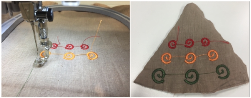
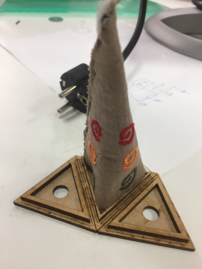
As a alternative modular shape, I created pyramid shape from fabric during the Week 17
24.5 3D printed connector piece (go up)
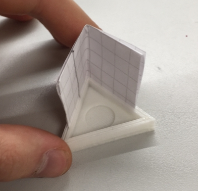
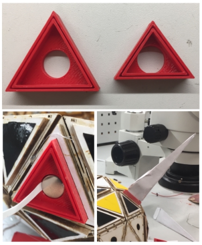
I created first prototype of the connector piece to connect paper shapes to the frame. The prototopy consist of triangle with a narrow hole to hold the paper. After folding normal paper few times, it got stuck easily to the connector piece. I will develop this further in future.
12.6 Testing the frame locking system (go up)
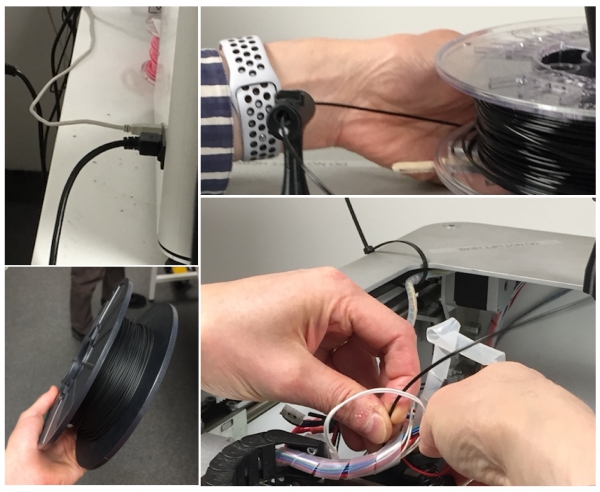
I tested to print the connector piece by using ninjaflex - flexible 3D printing material. I used machine new to me. I prepared the machine as seen below:
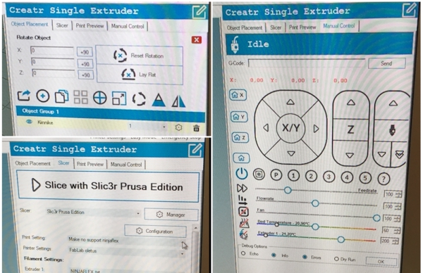
Then I opened software which was communicating with the 3d printer:
I used following settings to print my design:
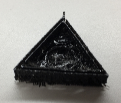
Print was not that detailed but the bending aspect was nice. For now, I will be using normal 3d plastic, but in the future, I may use ninjaflex to create flexible connector pieces for example for fabric parts.
14.6 Designing paper parts (go up)
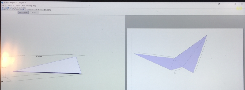
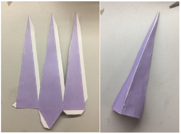
It was time to design modular pieces made of paper. I used Fusion 360 to do this. I tested dfferent designs but desided to use simple pyramid design for start.
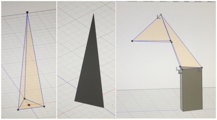
I exported Fusion 360 design as a .STL file to Pepakura designer software to create 2D folding pattern of the shape.
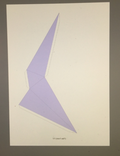
I exported peparakura folding patter as a .pdf file which I can in future use to laser cut the folding pattern. I created patterns for both small triangle pyramid and big triangle pyramid.
15.6 Laser cutting designed paper parts (go up)
I laser cut .pdf files which I made with Pepakura. I began by laser cutting big triangle pyramid from paper. The pyramid was way too big, something had went wrong in scaling:
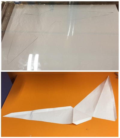
Next I laser cut small triangle pyramid. Scale was this time correct, and I folded and glued it together. The end result was a success:
16.6 Building paper parts by hand and 3d printing final connector pieces (go up)
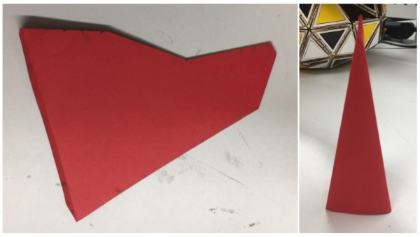
Folding laser cut paper parts was complicated because I didn´t cut instructions for folds. Therefore, I decided to create rest of the modular paper pieces by printing designed .pdf file and gluing it tohether as seen below.
I also finalized the connector pieces by creating design for both small and big triangle with a hole for a magnet. After sandpapering it a little bit, it fit very well to the frame and was durable even without the magnet:
17.6 Making part from rice paper (go up)
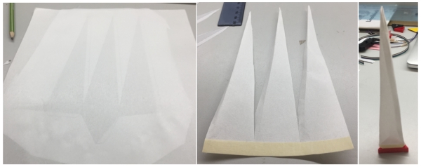
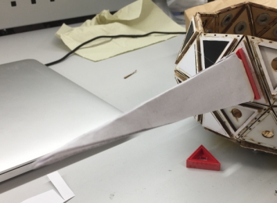
To shine RGB LED through paper piece, I used thin rice paper to fold pyramid. I also noticed that the paper pieces fit firmly to connector pieces when I add 4-5 layers of glued paper or tape on the bottom part of folded shapes.
INNER PART
1.5 Fastening strap (go up)
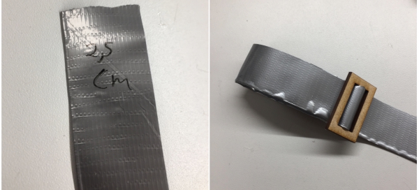
To be able to fasten the helmet on my face, I created simple strap lock in Fusion 360 and lasercutted it. I test it with a masking tape strap. It worked fine.
14.5 3d printing buckle strap (go up)
To connect the fastening strip and test my electricity strap idea introduced during the Week 17, I 3d printed buckle strap design found from internet
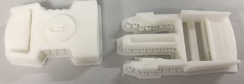
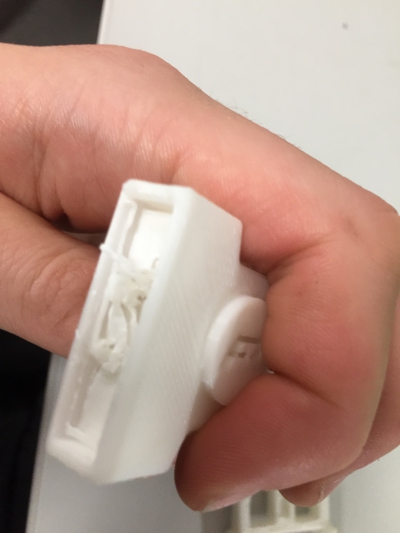
However, I used printer that couldn´t print support material, therefore I couldn´t remove material inside the buckle strap. I try to print this again in future.
ELECTRONICS
11.5 Thinking about the wiring (go up)
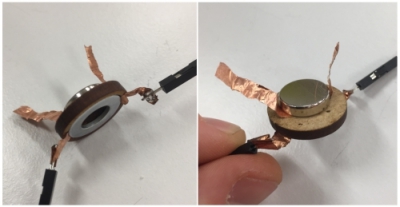
When I had decided hole engraving design, I began to thin wiring. My first test was to use copper sticker that was bended through the hole. This method worked and I was able to get current from one side of the design to other. Therefore, I decided to use this method also in my final helmet.
31.5 Megumi´s neopixels (go up)
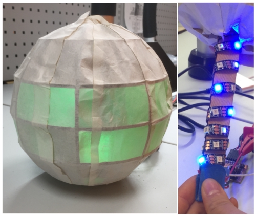
My class mate, Megumi, used neopixels to create light-changing led effect inside of her final project. I got excited about the effect and wanted to use it also in my final project to light up modular pieces. However, I don´t have enough time to implement this before the deadlie so I decided to do it later this year. For now, I´m just focusing on flashing individual leds. Mequmi´s neopixel-effects can be seen bellow
14.6 Thinking about the package of the board (go up)
For my final project, I will be using boards I made during the previous assigment weeks:
- Main board (Week11) to send and collect data
- Light sensor board (Week11) to regonize changed brightness
- RGB LED board (Week12) to shine modular paper pieces
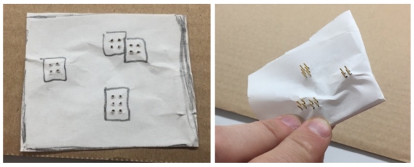
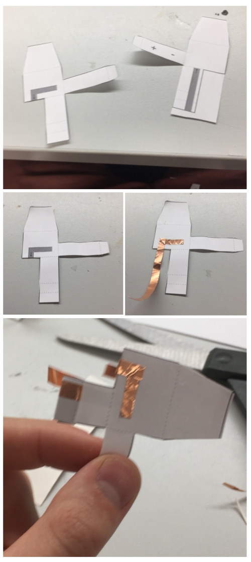
I want to create a package for my main board to attach it to my helmet. Therefore, I began to think about the design. I used paper to measure the size and placements of the pin headers:
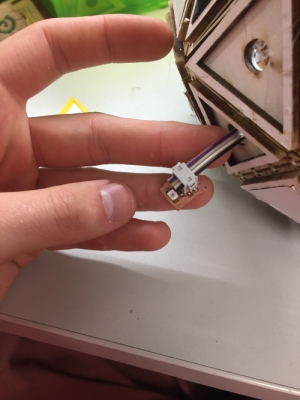
I have to wire up light sensor and RGB LED board through the helmet which limits possibilities to attach them to helmet
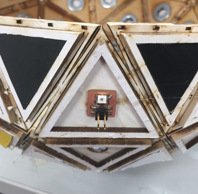
For now, I attached light sensor board with a magnet to the frame. In future, I will create a triangle board where the pinheader is facing the frame so that I can hide cords completly
15.6 Building a battery holder and testing the package (go up)
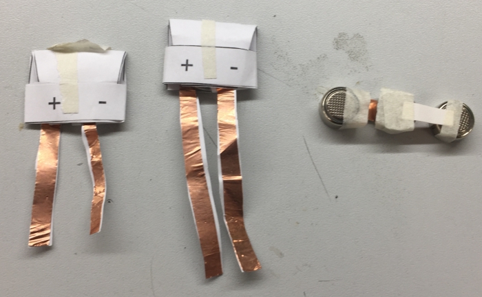
To power up my main board, I have to connect battery or batteries to it. I decided to use 3V button battery. To be able to connect it easily to the board, I created button battery holder by following this Tutorial. The process can be seen below:
Battery holder was a success. I made few of them and a chain of 1.5v batteries. Now I can attach either 3v, 4.5v or 6v battery to my board as a power source.
Next I continued package designing and created first cutting design by using This website. I laser cut this design and modified the top part by adding a engraving to hold a magnet:
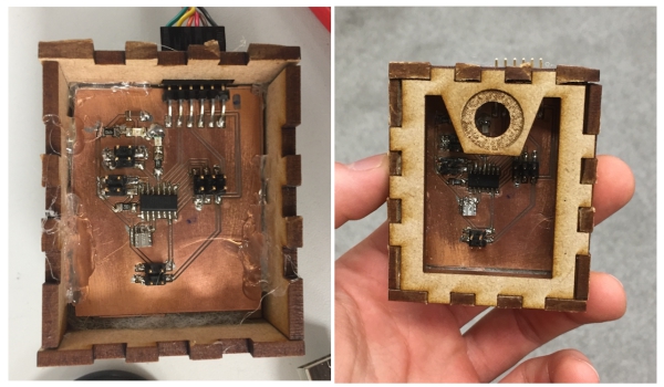
The package was success and I managed to connect it with a magnet to the frame. However, I want to show my board for people so in future I will design the box so that the board is visible.
16.6 Packaging new version of the board (go up)
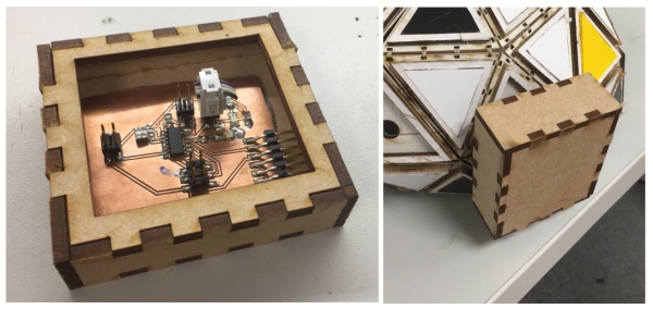
My main board broke so I had to mill and solder new one:

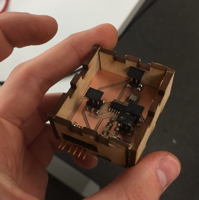
I modified the box to fit around this board:
17.6 Developing the package and boards (go up)
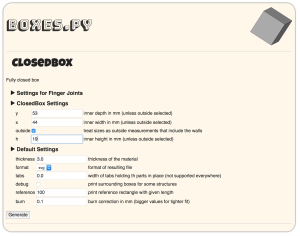
I finalized the package. I used following values in boxes.py site to generate my box:
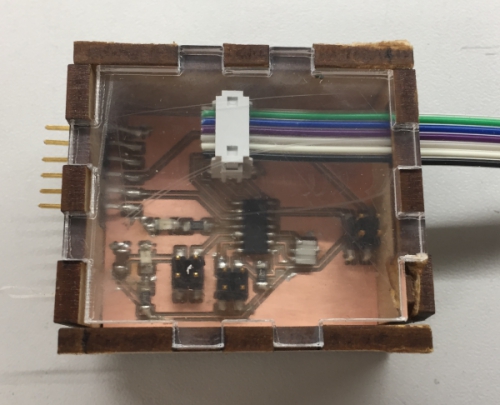
I laser cut top part from transparent material to make my electronics visible.
I added lasercut triangle with a magnet behind the part to be able to attach the board to my helmet:
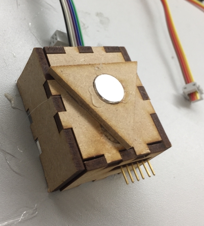
New design looked good and I decided to use it for my helmet:
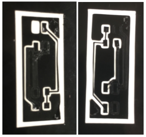
To create boards with pin header on another side of the board, I tested to create vinyl board layout with a vinyl cutter. I began by testing black vinyl. I was able to cut it and remove unneccessary vinyl around the pads:
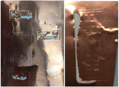
However, when I tried same with a copper sticker, I either cut too strong or too lightly to be able to get the board which I needed. This was probably due to the needle of our vinyl cutter. Due to this, I decided to forget this method and create my boards in future by soldering pin headers through the holes in normal board.
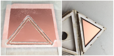
To prepare for this soldering process, I drew triangle board interior in Eagle so that it fit to small triangle in my frame. I will develop this further in coming days.
18.6 Prototyping two sided board (go up)
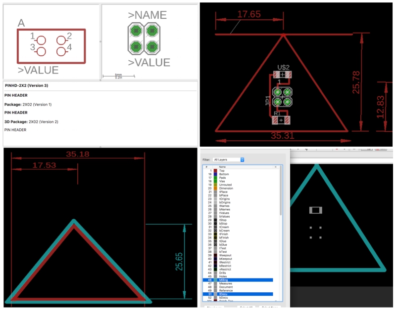
I continued developing my triangular board by adding components and holes to it in Eagle. Then I saved interior, traces and holes as individual image files:
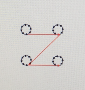
When I prepared the images for cutting in fabmodules, holes cutting process looked like this
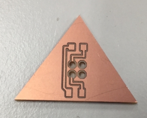
This lead to failure because the holes were too big and there were no coopper around the holes to solder pin headers:
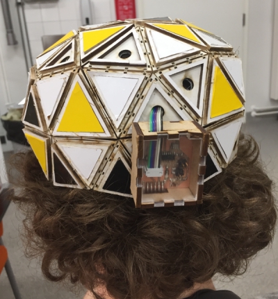
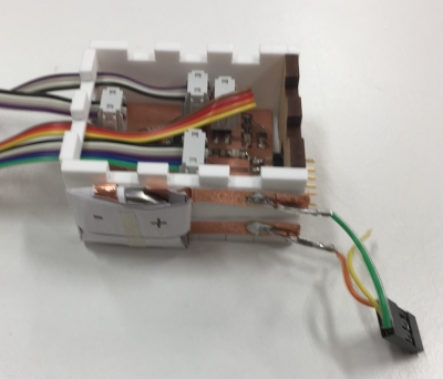
I finalized cord attachments for my main board, I used same connections for RGB led board and light sensor as during the Week 11 and 12. I also attached 3V battery on the side of the box:
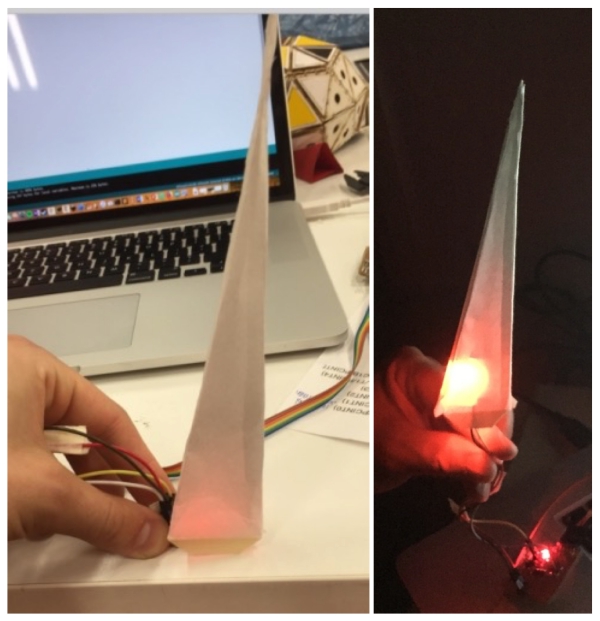
Then I connected main board to RGB LED, run RGB led code made during the week 12, to test how the RGB LED lighted rice paper shape from inside. The effect was alright both in light and dark.
19.6 Finishing the boards (go up)
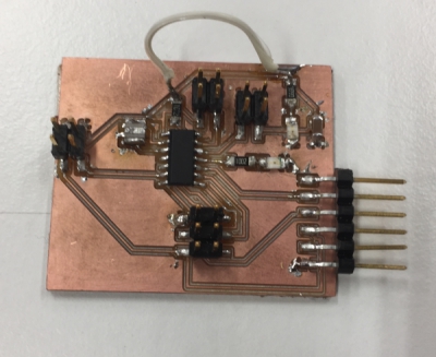
Unfortunatelly, I managed to breal one VCC line of the mainboard. Therefore, I used jumper cord to connect VCC lines together:
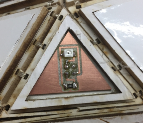
I finished triangular light sensor board and attached it to the helmet. Then I run light sensor code which I made during during the Week 11 to it to tested that it was working. It was working.
Next I connected light sensor board, RGB LED board and main board together with cords hiden into the helmet. I sewed the cords firmly to frame so that they were not hitting my head. Wiring was success and I managed to wear the helmet without feeling the cords or headers touching my head.

20.6 Finishing the software (go up)
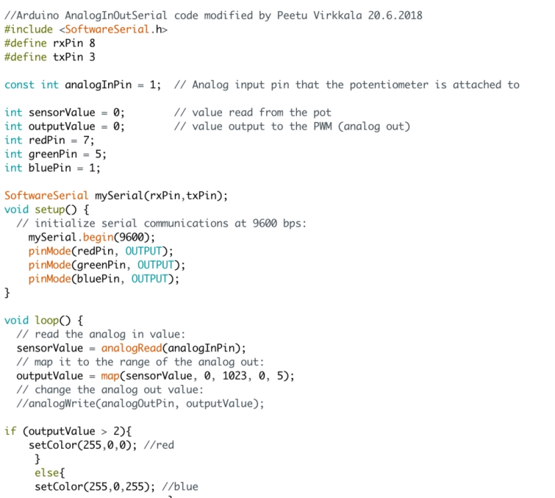
To get RGB LED and light sensor board to co-operate together, I combined their codes together to one arduino file. Whenever the light sensor value goes over or under 3, color of the RGB LED changes between blue (3>) and red (3<).
VISUAL
28.5 Screenscrip for the video (go up)
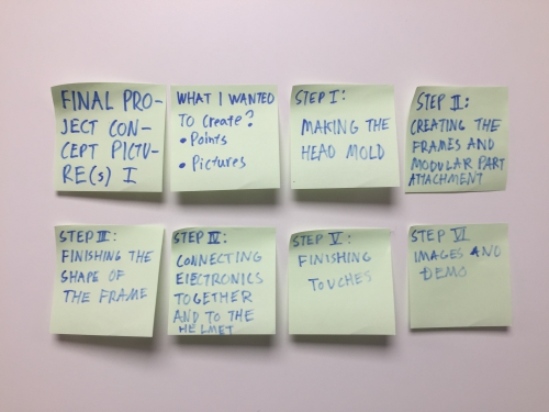
I created following screenscrip for my final project video. I will be following it when I´m filming the video.
20.6 RESULTS (go up)
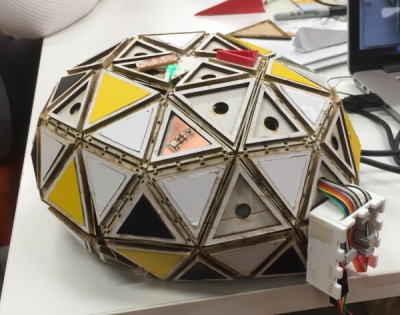
Here is the end result of the helmet without modular pieces...:
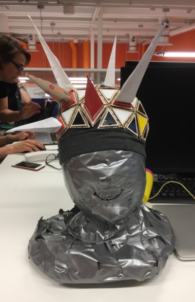
And with different modular pieces attached to it:
To sum up the end result of the project:
FINAL BILL OF THE MATERIALS:
GOOD RESULTS IN:
- Modular frame - helmet frame was finished
- Cover frames and stickers parts - Were finished and could be attached to the helmet
- Connector pieces - Were finished and could be attached to the helmet
- Folded parts (paper, fabric..) - Were finished and could be attached to the helmet
- Main Board/Main Board Box - Was finished and cords were hiden inside the helmet
- RGB LED and light sensor boards - Were finished and were attached and controlled by main board
- Combined code for RGB LED, light sensor and main boards - was done by combining previous codes together
THINGS THAT I DIDN´T MANAGE TO DO IN THIS SCEDULE:
- Modular frame for the full head
- Create more interesting modular parts
- Finish the inner part of the helmet
- Get battery to work with the main board
- Develop the program further
- Create more visual appeling material of my final project
THINGS THAT I WILL DEVELOP FURTHER AFTER THE DEADLINE:
- Everything listed above in "things i didn´t manage to do..." section
- Future development posibilities mentioned in "Invention, intellectual property and income" part
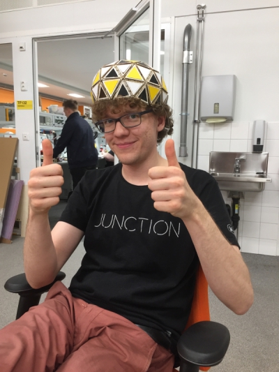
Overall, I´m happy with the end result of my final project. This course has been best course I have ever attended and I have learned so much new stuff during the last half year. I thank everyone who was organizing it, helping me, strugling through with me and you who had interess and disipline to read this through. Thumbs up for you!
FILES
(Files made during the previous assigment week´s can be found at the end of corresponding assigment pages)
FRAME
MODULAR PIECES
INNER PART
ELECTRONICS

This work is licensed under a Creative Commons Attribution 4.0 International License.
MODULAR PIECES
4.5 Designing the frame part locking system, 21.5 Embroidery design, 24.5 3D printed connector piece,12.6 Testing the frame locking system, 14.6 Designing and printing paper parts, 15.6 Laser cutting designed paper parts, 17.6 Making part from rice paper, 16.6 Building paper parts by hand and 3d printing final connector pieces
INNER PART
1.5 Fastening strip, 14.5 3d printing connecting strip
ELECTRONICS
11.5 Thinking about the wiring, 31.5 Megumi´s neopixels, 14.6 Thinking about the package of the board, 15.6 Building a battery holder and testing the package, 16.6 Packaging new version of the board, 17.6 Developing the package and boards, 18.6 Prototyping two sided board, 19.6 Finishing the boards, 20.6 Finishing the software
VISUAL & OVERALL
27.4 Creation of the mannequin head, 28.5 Screenscrip for the video, 20.6 RESULTS
FINAL PROJECT (SLIDE) (VIDEO)
In Details
SYNOPSYS
What is my final project? (go up)
My final project is a fabricated helmet which enables user´s to construct modular shapes on the top of the helmet.
By doing this, users can create unique helmet designs for visual and artistic purposes. As a finishing touch, led´s
can be connected to these modular shapes and controlled by users. WEEK 1 decribes the concept in more detail
Status: (go up)
DONE Mannequin head, Fastening strip
UNDONE Frame part locking system, Frame fitting system, Modular pieces
How I´m aiming to create it? (go up)
In short: my creation process goes forward as follows:
Build the frame
Build the modular pieces
Create visual material
Expand the project if there is still time
Applications and implications (go up)
What will it do?
My final project, modular helmet creates a versatile building surface on the top of your head. This surface can be used to create unique designs on the top of your head by using different kind of materials and electronics. With theses designs, users can act as different characters.
The helmet consist of modular MDF structures that are bonded together so that the helmet adapts to user´s head so that it can be taken off and put on the head with ease. Modular pieces are made by the user according to his or her´s needs and attached to helmet either directly or by using 3d printed frame-modular piece connectors. Connection between modular pieces and the helmet is achieved by connecting strong ferromagnets in modular pieces to metal washers inside the helmet. Because of this, modular pieces can be attached and unattached easily. Even so, the magnetic bond between the ferromagnet and metallic washer is capable of holding the weight and shape of even more heavier and complex materials like metal and wood.
Electronics of the helmet include a mainboard, a lightsensor board and an individual LED boards which are powered by two 3V button batteries. The lightsensor board measures chages in the room lighting, mainboard gets this information and controls the brightness and On/Off situation of individual LED´s. Goal of this electronic system is to illuminate helmet in dark environment to higlight existing details like shapes of modular pieces and create new visual elements like fast light patterns.
Who's done what beforehand?
There are multiple Fabacademy students that have created different kind of helmets before me. As a final project, Jasmin Rubinovitz created bike helmet by using composites whereas there are multiple tutorials online which teach how to build led interface for motorcycle helmet motorcycle helmet. Hovewer, I didn´t found modular helmet designs that connect both electronics and modular design.
My modular helmet is made of the modular pieces, the frame and of the inner part. For the frame, I have got lot of ideas from Yogi Kulkarni´s laser engraving assigment. He created a geodecim by using the laser cutter. I´m also using the laser cutter for similar kind of shape, so I used the geodecim calculators which he mentions on his page.
What will you design?
I will design the following things:
- Modular frame pieces
- Instructions to assemble modular pieces
- 3d printed modular-frame connector pieces
- Frame attachment solution for the inner part of the helmet
- Head attachment strip for the helmet
- Electronic board system to change the status of the LEDs according to the data got from the light sensor
- Board controlling interface
What materials and components will be used/ Where will they come from/ How much will they cost?
I listed my assumptions to following excel-template:

What parts and systems will be made?
The following parts will be made:
- Modular pieces from paper, fabric, and other materials like wood
- Modular-frame connector piece
- Electronic holders
- Frame made of modular triangle geodecim pieces

- Inner part of the helmet
The following systems will be made:
- Mainboard-ledBoards-LightSensor board system
What processes will be used?
Following processes will be used:
- Laser cutting = subtractive process: Creation of the frame pieces and frame parts for the frame pieces
- 3d printing = additive process: Creation of the modular-frame connector pieces
- Embroidering= additive process: Creation of few modular designs
- Board milling = Electronic production: Milling of the board system boards
- Embedded programming (C, Arduino)
- Input device: Light sensor
- Output devices: LEDs
What questions need to be answered?
How to connect modular frame parts together succesfully?
How to attach the frame to inner part of the helmet?
How to control LED´s?
How to achieve firm bond between the frame and modular pieces?
How to attach electronics?
How will it be evaluated?
My project will succeed if:
- The helmet can be put on and taken off from my head -> The structure is able to bend
- The helmet stays well on top of my head -> The frame is secured to inner part which is secured to my head
- Modular pieces can be created, connected and removed succesfully -> At least 10 modular pieces can be connected together to form the frame
- Input from light sensor is capable of changing the status of the LED´s -> The boards work and they are able to send eligible data to each other
What questions need to be answered?
- Is the helmet durable enough according to the current plan? If not, how to make it more durable?
- How the modular pieces could be designed on the top of 3d head model to enavble better fit?
- Could the helmet be build from the press-fit-kit? If could, how the helmet could be packed and sold for the customer?
What tasks need to be completed?
The following tasks should be completed:
- Design and build a durable frame that fits your head
- Design and build different modular designs and connector pieces that can be used to attach designs to the frame
- Design and build the inner part that is connected to the frame and to my head firmly
- Design and build electric board-system that works according to requirements
- Design and build system that attaches electric board system to the frame
- Document and visualize the helmet
What is the schedule
From the 27.5 to 20.6 the schedule is as follows:
28.5-3.6 Focus on finishing the documentation of week projects. When some extra time, develop the frame further
4.6-10.6 Finish the documentation and finish the frame and the method to connect modular pieces
11.6-17.6 Finish the electronics, inner part attachment system and documenting
17.6-20-6 Create presentation and visual material for the helmet.
In future: Develop the helmet design and technology forward for the own use and even for the commercial purposes
Invention, intellectual property and income (go up)
- Develop a plan for dissemination of your final project (Individual)
- Prepare a summary slide (presentation.png, 1280x1024) and video clip (presentation.mp4, 1080p HTML5, < ~minute, < ~10 MB)
in your root directory
Thinking about the legal and business future of the project
Intellectual property
To be able to develop my final project further after its completion, I spent part of this week by considering intellectual property rights.
What is my motivation behind the project
From the start, I have planned that my helmet is made to fulfill my personal needs. I like to act as a different fictional character - especially more mysterious and unreal characters. I prefer to create my own characters and act as them instead of acting as other characters. Therefore, I want to use my helmet as a prop to realize some of these characters visually and functionally in artist manner. Because this, I feel that there is a high possibility that I will develop and expand this project further in future.
Future opportunities and business opportunities
I believe that humans will begin to use more and more functional headpieces (masks, helmet, etc.) to exploit AI and IoT possibilities as a part of their daily lives. I feel that these headpieces will have also a fashion purpose which leads people to use them just even for their visual features. I think that headpieces which combine technology, modularity, and opportunity for self-expression in these times will be the winners of this market.
These beliefs reflect my final project, where I aim to design modular an functional smart helmet which users can use to express themselves. Currently, I feel that there lies a demand for a modular helmet making kit which customers can use to create unique helmet designs around their heads and modify them according to their needs to express themselves through the helmets with help of modular designs and embedded technologies like screens, LEDs and Arduino's.
There are multiple ways how these helmets could be sold, for example:
- Design and order model
Customers use their phones to create a 3D model of their head and upload it to helmet firm´s web page or app. From there, users could create or generate helmet frame that fits perfectly to their head. Then, the user could order these parts as a construction kit to their home or optionally as a full assembled helmet.
- Buy the basic kit, build your own
To easier the manufacturing, the helmet kit could be sold as a one standard package, that could still be used to create a frame for almost all different human head shapes. This could be achieved for example by using small triangles, which enables huge customizing possibilities.
- Build ready made helmet
Helmets are made as ready-made frames. The user can customize the helmet only through modular designs and embedded technologies.
Add-on-possibilities could be provided for example by:
- Sell Add-on possibilities to helmets
Provide a specific range of products like modular pieces and embedded technologies that can be added by the user to the helmet.
- Let users design their own add-ons
Design the helmet so that the users can create their own modular helmet pieces and embedded aspects and share them
Helmet could be manufactured for example by:
- Use Fablabs or Fablab-kind of producing spaces
- By subcontracting parts and/or assembling needed for example from China
From these, I feel that Design and order model, let users design their own add-ons, usage of Fablabs or Fablab-kind of producing spaces would be the best combination for the future. If I´m able to design this kind of helmet and/or helmet design software, I will consider taking it to market by creating a startup around it and by gathering investments through investors, funding, Kickstart and through other possibilities.
Licenses and sharing
Addition to future and business opportunities, I also considered different licensing possibilities. Many of the licenses listed on this week´s site are meant mainly for software purposes. For example, MIT license is a software license created at MIT. This license allows others to reuse licensed work with limited restriction which is that all of the licensed software have to include the MIT permission notice. Gnu general public licenses allow users to copy, distribute and modify the software as long as all the changes and dates in source files are tracked and as long as made modifications are available under the GNU GPL with appropriate install & build instructions.
However, currently, my project is mainly just a physical product with minimal software functionalities. FAB license could be used for my physical product to get my "project name" acknowledged and copyrights retained if my work is reused. However, I´m more interested about Creative Commons License Attribution 4.0, because it enables me to share my project for others to develop further when still getting a credit of my work if the project is developed further by someone else.
If my project would develop further and I would be able to make the helmet constructing kit that has business potential, I would consider other options. But for now, Creative Commons License Attribution 4.0 is enough for me.
OVERALL
27.4 Creation of the mannequin head (go up)
I wanted to have mannequin head similar to my own head to visualize physically how my helmet should look like and how it should attach
to my head.
After researching different possibilities, I came to a conclusion that I want the mannequin head to be an exact copy of my own head shape.
Most common examples to do this include creating silicon mold and scanning and 3d printing your head. However, our lab didn´t have
necessary molding materials and 3d printing my head in 1:1 scale would be extremely expensive so I decided to use cheap but fulfilling
alternative method: masking tape, plastic food wrapping, and a polyurethane seal.
For this method, I used the help of two of my friends. I sat in a chair and my friends wrapped plastic food wrapping all around my head and
neck except the mouth area because I had to be able to breathe somehow. Then, they wrapped masking tape around my head following the shape
of my head:
When the masking tape wrapping was ready, my friends cut the mask off my head and I taped my mouth area and the cut back together. I had now
masking tape frame of my head:


Next, I had to fill the frame. I went outdoors, put spine made of newspaper inside the frame and sprayed polyurethane seal into the frame.
Then I left the polyurethane expand and harden for one day. When I came back, polyurethane had expanded and the frame had kept its shape.

Finally, I took the frame to Fablab, cut extra polyurethane and sealed bottom of the frame with a masking tape. Mannequin head was now ready!

FRAME:
6.5 Thinking about the size of the frame (go up)
Before designing the frame pieces, I used geomags on top of the mannequin helmet to test different shapes around the head. This test revealed that triangle shape fitted well for my use and I decided to use it as a base shape.

I also tried to use 3d head model stl model in Fusion 360 to design the frame around it. However, this was more complicated than I thought and I feeled more comfortable to design the frame to top of the real model. Therefore, I decided to give up 3D modelling and consentrate to physical modelling.

9.5 First big frame triangle prototype (go up)
I wanted to build frame from bendable parts so I researched more about living hinges made around triangles. I found Obrary´s free living hinge designs. They had specific living hinge design designed to create bendable triangles:

After inspecting the design, I created my own version of the design in Fusion 360 and edited it in Inkscape, I wasn´t sure if it would work.

However, when I lasercutted it, the design was working fine.

It could be bended from the sides and the living hinge structure was strong. I decided to use this design for my final project. I also made hole on to middle of the design for 8mm washer to attach ferromagnets later on. Next step was to decide the size of the triangle.

11.5 Cutting settings, copper sticker and triangle chain (go up)
As a next step of my frame piece designing, I designed two pieces connected together to ensure that bending frame pieces could be connected together.

The design worked well and the pieces could be bended over 90 degrees:

Next I created chain of these triangles to see how they bend around the mannequin head:


It bend well around the mannequin head:

I wasn´t happy with the mitters between the parts, therefore, I designed hexagons build from these triangles

However, This time mitters at the middle of the pieces were still bad. Therefore I decided to design this triangular design further in future
I also decided the engraving parameters for the washer holder hole. First I designed hole for engraving and placed it at the middle of the triangle design:

I tested different engraving settings for MDF and decided to use Normal mdf engraving settings (40%) and engrave the hole 4 times.

When the engraving was finished, I sandpapered it and attached the washer. The engraving was perfect and the washer could be stuck inside without the glue:

14.5 Creating frames, frame patterns and sewing holes (go up)
I created frame parts on the top of the triangle pieces to cover them with colorfull material when they are not in use. First proto can be seen below:

Frames with black and yellow vinyl stickers can be seen below. I liked the frame design and desided to use it:

Next I tested different frame part chains. Firts I created chain:


Then I created frame design by using two different kind of triangle sizes: 1 A triangle on the middle and 3 B triangle around:

However, these triangles couldn´t be cut as a chain because their overall angle was over 360 degree as seen below:

To add them toghether, I designed holes for sewing on the edges of the pieces:

Then I used spandex cord to connect them together:

Even thou the sewing was time consuming, it worked well and I decided to use it as my method to connect the pieces together.


18.5 Sewing and testing different materials (go up)
I sewed two frame parts together, the end result looked nice:

However, when I sewed multiple parts together, I run out of the spandex cord and the overall shape wasn´t symmetric. To fix this, I decided to use in future parts with fewer sewing holes and sew parts as two sewed part pieces (as seen above) to be able to connect the parts symmetrically together.

I didn´t liked that much of the color and the smell of MDF, so I tested different materials and finishin method for frame parts. I began by cutting acrylic piece. It was not flexible enough:

I sprayed MDF but the color and the smell was not good:

Finally, I glued paper on the top of MDF board...

...and laser cut it. The end result looked good, little woody, and I decided to use it in my project.

For this method, Following are the best cutting settings on bigger Epilog laser...

... and smaller Epilog laser:

22.5 Birchbark test and first bigger assembling (go up)
I made design with less sewing holes and used fishing line (right) instead of spandex (left):

Then I sewed few bigger frame parts together...

...and sewed them together, however, there were gaps when I put the helmet on the top of the mannequin head. Mannequin head was little bigger than my head and I had some errors in my sewings. I have to fix this in the future:

I also found out that we had birchwood bark in our lab. I decided to test it as a surface materia. I glued it on the MDF and handled the top part with the glue water.

End result looked good. I´m planning to use birchwood in my future projects to get similar finishing touch to my projects:

30.5 Second bigger assembling (go up)
Instead of mannequin head, I tested to sew the frame parts together and put the resulting shape on the top of my head:

I found a method to connect the parts together so that I could fit the resulting shape on the top of the mannequin head. I decided to use this design:

1.6 First version of the frame (go up)
When I sewed the frames together, sometimes the sewing hole broke. I fixed this with a hot glue.

Due to the way which I connected frame parts together, there was a gap on the top middle point of the helmet:

I began to fix it by drawing part that was size of the hole:

Then I measured the part and made it in Fusion 360:

Finally I sewed it onto its place. It fitted well:

Even thou I want to make full head helmet, MVP of the helmet was now ready, and I decided to use it for my final project:


7.6 Creating frames for the frame (go up)
I build frame on top of the frame part

I prepared the part by sandpapering and gluing it

It looked good so I decided to fill whole helmet with it

Sticker parts fitted well

I filled all frames. It looked nice.

12.6 Finishing stickers and adding washers (go up)

I hotglued 8mm washers under the frame. Now I could attach parts with magnets to the frame:

MODULAR PIECES
4.5 Designing the frame part locking system (go up)
I used two laser cutted triangles to help me to visualize possible locking system. In the end, I decided to use paper as an outer parts material.
Locking system has to fulfill following requirements:
- User can fold and glue 3d paper form that can be attached to locking system
- Locking system is able to sustain weight of simple and more complex paper formations


I got few different locking system ideas. First one was an idea to make thin gap where the paper would be pushed:

This idea was ineffective so I decided to try something else.
Next idea was to create some kind of locking parts like in lego´s by using 3d printing or molding:
To test this idea, I created parametric Lego-like block and 3d printed it:

However, the 3d printing was not detailed enough, so I decided to test alternative solutions

Third idea was to use magnetic tape to attach paper and the frame together:

However, the connection was not durable when I attached more weight for the tape. I would need more powerfull magnetic tape:

Fourth and my chosen idea was to create connections by using stron ferromagnets and metal rings. Metal rings would be embedded
to triangle´s and ferromagnets would be attached to paper pieces. This connection was strong, durable and easy to tear appart.
21.5 Embroidery design (go up)
As a alternative modular shape, I created pyramid shape from fabric during the Week 17


24.5 3D printed connector piece (go up)
I created first prototype of the connector piece to connect paper shapes to the frame. The prototopy consist of triangle with a narrow hole to hold the paper. After folding normal paper few times, it got stuck easily to the connector piece. I will develop this further in future.

12.6 Testing the frame locking system (go up)
I tested to print the connector piece by using ninjaflex - flexible 3D printing material. I used machine new to me. I prepared the machine as seen below:

Then I opened software which was communicating with the 3d printer:

I used following settings to print my design:

Print was not that detailed but the bending aspect was nice. For now, I will be using normal 3d plastic, but in the future, I may use ninjaflex to create flexible connector pieces for example for fabric parts.

14.6 Designing paper parts (go up)
It was time to design modular pieces made of paper. I used Fusion 360 to do this. I tested dfferent designs but desided to use simple pyramid design for start.

I exported Fusion 360 design as a .STL file to Pepakura designer software to create 2D folding pattern of the shape.

I exported peparakura folding patter as a .pdf file which I can in future use to laser cut the folding pattern. I created patterns for both small triangle pyramid and big triangle pyramid.

15.6 Laser cutting designed paper parts (go up)
I laser cut .pdf files which I made with Pepakura. I began by laser cutting big triangle pyramid from paper. The pyramid was way too big, something had went wrong in scaling:

Next I laser cut small triangle pyramid. Scale was this time correct, and I folded and glued it together. The end result was a success:

16.6 Building paper parts by hand and 3d printing final connector pieces (go up)
Folding laser cut paper parts was complicated because I didn´t cut instructions for folds. Therefore, I decided to create rest of the modular paper pieces by printing designed .pdf file and gluing it tohether as seen below.

I also finalized the connector pieces by creating design for both small and big triangle with a hole for a magnet. After sandpapering it a little bit, it fit very well to the frame and was durable even without the magnet:

17.6 Making part from rice paper (go up)
To shine RGB LED through paper piece, I used thin rice paper to fold pyramid. I also noticed that the paper pieces fit firmly to connector pieces when I add 4-5 layers of glued paper or tape on the bottom part of folded shapes.


INNER PART
1.5 Fastening strap (go up)
To be able to fasten the helmet on my face, I created simple strap lock in Fusion 360 and lasercutted it. I test it with a masking tape strap. It worked fine.

14.5 3d printing buckle strap (go up)
To connect the fastening strip and test my electricity strap idea introduced during the Week 17, I 3d printed buckle strap design found from internet

However, I used printer that couldn´t print support material, therefore I couldn´t remove material inside the buckle strap. I try to print this again in future.

ELECTRONICS
11.5 Thinking about the wiring (go up)
When I had decided hole engraving design, I began to thin wiring. My first test was to use copper sticker that was bended through the hole. This method worked and I was able to get current from one side of the design to other. Therefore, I decided to use this method also in my final helmet.

31.5 Megumi´s neopixels (go up)
My class mate, Megumi, used neopixels to create light-changing led effect inside of her final project. I got excited about the effect and wanted to use it also in my final project to light up modular pieces. However, I don´t have enough time to implement this before the deadlie so I decided to do it later this year. For now, I´m just focusing on flashing individual leds. Mequmi´s neopixel-effects can be seen bellow

14.6 Thinking about the package of the board (go up)
For my final project, I will be using boards I made during the previous assigment weeks:
- Main board (Week11) to send and collect data
- Light sensor board (Week11) to regonize changed brightness
- RGB LED board (Week12) to shine modular paper pieces
I want to create a package for my main board to attach it to my helmet. Therefore, I began to think about the design. I used paper to measure the size and placements of the pin headers:

I have to wire up light sensor and RGB LED board through the helmet which limits possibilities to attach them to helmet

For now, I attached light sensor board with a magnet to the frame. In future, I will create a triangle board where the pinheader is facing the frame so that I can hide cords completly

15.6 Building a battery holder and testing the package (go up)
To power up my main board, I have to connect battery or batteries to it. I decided to use 3V button battery. To be able to connect it easily to the board, I created button battery holder by following this Tutorial. The process can be seen below:

Battery holder was a success. I made few of them and a chain of 1.5v batteries. Now I can attach either 3v, 4.5v or 6v battery to my board as a power source.

Next I continued package designing and created first cutting design by using This website. I laser cut this design and modified the top part by adding a engraving to hold a magnet:

The package was success and I managed to connect it with a magnet to the frame. However, I want to show my board for people so in future I will design the box so that the board is visible.

16.6 Packaging new version of the board (go up)
My main board broke so I had to mill and solder new one:

I modified the box to fit around this board:

17.6 Developing the package and boards (go up)
I finalized the package. I used following values in boxes.py site to generate my box:

I laser cut top part from transparent material to make my electronics visible.

I added lasercut triangle with a magnet behind the part to be able to attach the board to my helmet:

New design looked good and I decided to use it for my helmet:

To create boards with pin header on another side of the board, I tested to create vinyl board layout with a vinyl cutter. I began by testing black vinyl. I was able to cut it and remove unneccessary vinyl around the pads:

However, when I tried same with a copper sticker, I either cut too strong or too lightly to be able to get the board which I needed. This was probably due to the needle of our vinyl cutter. Due to this, I decided to forget this method and create my boards in future by soldering pin headers through the holes in normal board.

To prepare for this soldering process, I drew triangle board interior in Eagle so that it fit to small triangle in my frame. I will develop this further in coming days.

18.6 Prototyping two sided board (go up)
I continued developing my triangular board by adding components and holes to it in Eagle. Then I saved interior, traces and holes as individual image files:

When I prepared the images for cutting in fabmodules, holes cutting process looked like this

This lead to failure because the holes were too big and there were no coopper around the holes to solder pin headers:

I finalized cord attachments for my main board, I used same connections for RGB led board and light sensor as during the Week 11 and 12. I also attached 3V battery on the side of the box:

Then I connected main board to RGB LED, run RGB led code made during the week 12, to test how the RGB LED lighted rice paper shape from inside. The effect was alright both in light and dark.

19.6 Finishing the boards (go up)
Unfortunatelly, I managed to breal one VCC line of the mainboard. Therefore, I used jumper cord to connect VCC lines together:

I finished triangular light sensor board and attached it to the helmet. Then I run light sensor code which I made during during the Week 11 to it to tested that it was working. It was working.

Next I connected light sensor board, RGB LED board and main board together with cords hiden into the helmet. I sewed the cords firmly to frame so that they were not hitting my head. Wiring was success and I managed to wear the helmet without feeling the cords or headers touching my head.

20.6 Finishing the software (go up)
To get RGB LED and light sensor board to co-operate together, I combined their codes together to one arduino file. Whenever the light sensor value goes over or under 3, color of the RGB LED changes between blue (3>) and red (3<).

VISUAL
28.5 Screenscrip for the video (go up)
I created following screenscrip for my final project video. I will be following it when I´m filming the video.

20.6 RESULTS (go up)
Here is the end result of the helmet without modular pieces...:

And with different modular pieces attached to it:

To sum up the end result of the project:
FINAL BILL OF THE MATERIALS:

GOOD RESULTS IN:
- Modular frame - helmet frame was finished
- Cover frames and stickers parts - Were finished and could be attached to the helmet
- Connector pieces - Were finished and could be attached to the helmet
- Folded parts (paper, fabric..) - Were finished and could be attached to the helmet
- Main Board/Main Board Box - Was finished and cords were hiden inside the helmet
- RGB LED and light sensor boards - Were finished and were attached and controlled by main board
- Combined code for RGB LED, light sensor and main boards - was done by combining previous codes together
THINGS THAT I DIDN´T MANAGE TO DO IN THIS SCEDULE:
- Modular frame for the full head
- Create more interesting modular parts
- Finish the inner part of the helmet
- Get battery to work with the main board
- Develop the program further
- Create more visual appeling material of my final project
THINGS THAT I WILL DEVELOP FURTHER AFTER THE DEADLINE:
- Everything listed above in "things i didn´t manage to do..." section
- Future development posibilities mentioned in "Invention, intellectual property and income" part
Overall, I´m happy with the end result of my final project. This course has been best course I have ever attended and I have learned so much new stuff during the last half year. I thank everyone who was organizing it, helping me, strugling through with me and you who had interess and disipline to read this through. Thumbs up for you!

FILES
(Files made during the previous assigment week´s can be found at the end of corresponding assigment pages)
FRAME
MODULAR PIECES
INNER PART
ELECTRONICS

This work is licensed under a Creative Commons Attribution 4.0 International License.
INNER PART
1.5 Fastening strip, 14.5 3d printing connecting strip
ELECTRONICS
11.5 Thinking about the wiring, 31.5 Megumi´s neopixels, 14.6 Thinking about the package of the board, 15.6 Building a battery holder and testing the package, 16.6 Packaging new version of the board, 17.6 Developing the package and boards, 18.6 Prototyping two sided board, 19.6 Finishing the boards, 20.6 Finishing the software
VISUAL & OVERALL
27.4 Creation of the mannequin head, 28.5 Screenscrip for the video, 20.6 RESULTS
FINAL PROJECT (SLIDE) (VIDEO)
In Details
SYNOPSYS
What is my final project? (go up)
My final project is a fabricated helmet which enables user´s to construct modular shapes on the top of the helmet.
By doing this, users can create unique helmet designs for visual and artistic purposes. As a finishing touch, led´s
can be connected to these modular shapes and controlled by users. WEEK 1 decribes the concept in more detail
Status: (go up)
DONE Mannequin head, Fastening strip
UNDONE Frame part locking system, Frame fitting system, Modular pieces
How I´m aiming to create it? (go up)
In short: my creation process goes forward as follows:
Build the frame
Build the modular pieces
Create visual material
Expand the project if there is still time
Applications and implications (go up)
What will it do?
My final project, modular helmet creates a versatile building surface on the top of your head. This surface can be used to create unique designs on the top of your head by using different kind of materials and electronics. With theses designs, users can act as different characters.
The helmet consist of modular MDF structures that are bonded together so that the helmet adapts to user´s head so that it can be taken off and put on the head with ease. Modular pieces are made by the user according to his or her´s needs and attached to helmet either directly or by using 3d printed frame-modular piece connectors. Connection between modular pieces and the helmet is achieved by connecting strong ferromagnets in modular pieces to metal washers inside the helmet. Because of this, modular pieces can be attached and unattached easily. Even so, the magnetic bond between the ferromagnet and metallic washer is capable of holding the weight and shape of even more heavier and complex materials like metal and wood.
Electronics of the helmet include a mainboard, a lightsensor board and an individual LED boards which are powered by two 3V button batteries. The lightsensor board measures chages in the room lighting, mainboard gets this information and controls the brightness and On/Off situation of individual LED´s. Goal of this electronic system is to illuminate helmet in dark environment to higlight existing details like shapes of modular pieces and create new visual elements like fast light patterns.
Who's done what beforehand?
There are multiple Fabacademy students that have created different kind of helmets before me. As a final project, Jasmin Rubinovitz created bike helmet by using composites whereas there are multiple tutorials online which teach how to build led interface for motorcycle helmet motorcycle helmet. Hovewer, I didn´t found modular helmet designs that connect both electronics and modular design.
My modular helmet is made of the modular pieces, the frame and of the inner part. For the frame, I have got lot of ideas from Yogi Kulkarni´s laser engraving assigment. He created a geodecim by using the laser cutter. I´m also using the laser cutter for similar kind of shape, so I used the geodecim calculators which he mentions on his page.
What will you design?
I will design the following things:
- Modular frame pieces
- Instructions to assemble modular pieces
- 3d printed modular-frame connector pieces
- Frame attachment solution for the inner part of the helmet
- Head attachment strip for the helmet
- Electronic board system to change the status of the LEDs according to the data got from the light sensor
- Board controlling interface
What materials and components will be used/ Where will they come from/ How much will they cost?
I listed my assumptions to following excel-template:

What parts and systems will be made?
The following parts will be made:
- Modular pieces from paper, fabric, and other materials like wood
- Modular-frame connector piece
- Electronic holders
- Frame made of modular triangle geodecim pieces

- Inner part of the helmet
The following systems will be made:
- Mainboard-ledBoards-LightSensor board system
What processes will be used?
Following processes will be used:
- Laser cutting = subtractive process: Creation of the frame pieces and frame parts for the frame pieces
- 3d printing = additive process: Creation of the modular-frame connector pieces
- Embroidering= additive process: Creation of few modular designs
- Board milling = Electronic production: Milling of the board system boards
- Embedded programming (C, Arduino)
- Input device: Light sensor
- Output devices: LEDs
What questions need to be answered?
How to connect modular frame parts together succesfully?
How to attach the frame to inner part of the helmet?
How to control LED´s?
How to achieve firm bond between the frame and modular pieces?
How to attach electronics?
How will it be evaluated?
My project will succeed if:
- The helmet can be put on and taken off from my head -> The structure is able to bend
- The helmet stays well on top of my head -> The frame is secured to inner part which is secured to my head
- Modular pieces can be created, connected and removed succesfully -> At least 10 modular pieces can be connected together to form the frame
- Input from light sensor is capable of changing the status of the LED´s -> The boards work and they are able to send eligible data to each other
What questions need to be answered?
- Is the helmet durable enough according to the current plan? If not, how to make it more durable?
- How the modular pieces could be designed on the top of 3d head model to enavble better fit?
- Could the helmet be build from the press-fit-kit? If could, how the helmet could be packed and sold for the customer?
What tasks need to be completed?
The following tasks should be completed:
- Design and build a durable frame that fits your head
- Design and build different modular designs and connector pieces that can be used to attach designs to the frame
- Design and build the inner part that is connected to the frame and to my head firmly
- Design and build electric board-system that works according to requirements
- Design and build system that attaches electric board system to the frame
- Document and visualize the helmet
What is the schedule
From the 27.5 to 20.6 the schedule is as follows:
28.5-3.6 Focus on finishing the documentation of week projects. When some extra time, develop the frame further
4.6-10.6 Finish the documentation and finish the frame and the method to connect modular pieces
11.6-17.6 Finish the electronics, inner part attachment system and documenting
17.6-20-6 Create presentation and visual material for the helmet.
In future: Develop the helmet design and technology forward for the own use and even for the commercial purposes
Invention, intellectual property and income (go up)
- Develop a plan for dissemination of your final project (Individual)
- Prepare a summary slide (presentation.png, 1280x1024) and video clip (presentation.mp4, 1080p HTML5, < ~minute, < ~10 MB)
in your root directory
Thinking about the legal and business future of the project
Intellectual property
To be able to develop my final project further after its completion, I spent part of this week by considering intellectual property rights.
What is my motivation behind the project
From the start, I have planned that my helmet is made to fulfill my personal needs. I like to act as a different fictional character - especially more mysterious and unreal characters. I prefer to create my own characters and act as them instead of acting as other characters. Therefore, I want to use my helmet as a prop to realize some of these characters visually and functionally in artist manner. Because this, I feel that there is a high possibility that I will develop and expand this project further in future.
Future opportunities and business opportunities
I believe that humans will begin to use more and more functional headpieces (masks, helmet, etc.) to exploit AI and IoT possibilities as a part of their daily lives. I feel that these headpieces will have also a fashion purpose which leads people to use them just even for their visual features. I think that headpieces which combine technology, modularity, and opportunity for self-expression in these times will be the winners of this market.
These beliefs reflect my final project, where I aim to design modular an functional smart helmet which users can use to express themselves. Currently, I feel that there lies a demand for a modular helmet making kit which customers can use to create unique helmet designs around their heads and modify them according to their needs to express themselves through the helmets with help of modular designs and embedded technologies like screens, LEDs and Arduino's.
There are multiple ways how these helmets could be sold, for example:
- Design and order model
Customers use their phones to create a 3D model of their head and upload it to helmet firm´s web page or app. From there, users could create or generate helmet frame that fits perfectly to their head. Then, the user could order these parts as a construction kit to their home or optionally as a full assembled helmet.
- Buy the basic kit, build your own
To easier the manufacturing, the helmet kit could be sold as a one standard package, that could still be used to create a frame for almost all different human head shapes. This could be achieved for example by using small triangles, which enables huge customizing possibilities.
- Build ready made helmet
Helmets are made as ready-made frames. The user can customize the helmet only through modular designs and embedded technologies.
Add-on-possibilities could be provided for example by:
- Sell Add-on possibilities to helmets
Provide a specific range of products like modular pieces and embedded technologies that can be added by the user to the helmet.
- Let users design their own add-ons
Design the helmet so that the users can create their own modular helmet pieces and embedded aspects and share them
Helmet could be manufactured for example by:
- Use Fablabs or Fablab-kind of producing spaces
- By subcontracting parts and/or assembling needed for example from China
From these, I feel that Design and order model, let users design their own add-ons, usage of Fablabs or Fablab-kind of producing spaces would be the best combination for the future. If I´m able to design this kind of helmet and/or helmet design software, I will consider taking it to market by creating a startup around it and by gathering investments through investors, funding, Kickstart and through other possibilities.
Licenses and sharing
Addition to future and business opportunities, I also considered different licensing possibilities. Many of the licenses listed on this week´s site are meant mainly for software purposes. For example, MIT license is a software license created at MIT. This license allows others to reuse licensed work with limited restriction which is that all of the licensed software have to include the MIT permission notice. Gnu general public licenses allow users to copy, distribute and modify the software as long as all the changes and dates in source files are tracked and as long as made modifications are available under the GNU GPL with appropriate install & build instructions.
However, currently, my project is mainly just a physical product with minimal software functionalities. FAB license could be used for my physical product to get my "project name" acknowledged and copyrights retained if my work is reused. However, I´m more interested about Creative Commons License Attribution 4.0, because it enables me to share my project for others to develop further when still getting a credit of my work if the project is developed further by someone else.
If my project would develop further and I would be able to make the helmet constructing kit that has business potential, I would consider other options. But for now, Creative Commons License Attribution 4.0 is enough for me.
OVERALL
27.4 Creation of the mannequin head (go up)
I wanted to have mannequin head similar to my own head to visualize physically how my helmet should look like and how it should attach
to my head.
After researching different possibilities, I came to a conclusion that I want the mannequin head to be an exact copy of my own head shape.
Most common examples to do this include creating silicon mold and scanning and 3d printing your head. However, our lab didn´t have
necessary molding materials and 3d printing my head in 1:1 scale would be extremely expensive so I decided to use cheap but fulfilling
alternative method: masking tape, plastic food wrapping, and a polyurethane seal.
For this method, I used the help of two of my friends. I sat in a chair and my friends wrapped plastic food wrapping all around my head and
neck except the mouth area because I had to be able to breathe somehow. Then, they wrapped masking tape around my head following the shape
of my head:
When the masking tape wrapping was ready, my friends cut the mask off my head and I taped my mouth area and the cut back together. I had now
masking tape frame of my head:


Next, I had to fill the frame. I went outdoors, put spine made of newspaper inside the frame and sprayed polyurethane seal into the frame.
Then I left the polyurethane expand and harden for one day. When I came back, polyurethane had expanded and the frame had kept its shape.

Finally, I took the frame to Fablab, cut extra polyurethane and sealed bottom of the frame with a masking tape. Mannequin head was now ready!

FRAME:
6.5 Thinking about the size of the frame (go up)
Before designing the frame pieces, I used geomags on top of the mannequin helmet to test different shapes around the head. This test revealed that triangle shape fitted well for my use and I decided to use it as a base shape.

I also tried to use 3d head model stl model in Fusion 360 to design the frame around it. However, this was more complicated than I thought and I feeled more comfortable to design the frame to top of the real model. Therefore, I decided to give up 3D modelling and consentrate to physical modelling.

9.5 First big frame triangle prototype (go up)
I wanted to build frame from bendable parts so I researched more about living hinges made around triangles. I found Obrary´s free living hinge designs. They had specific living hinge design designed to create bendable triangles:

After inspecting the design, I created my own version of the design in Fusion 360 and edited it in Inkscape, I wasn´t sure if it would work.

However, when I lasercutted it, the design was working fine.

It could be bended from the sides and the living hinge structure was strong. I decided to use this design for my final project. I also made hole on to middle of the design for 8mm washer to attach ferromagnets later on. Next step was to decide the size of the triangle.

11.5 Cutting settings, copper sticker and triangle chain (go up)
As a next step of my frame piece designing, I designed two pieces connected together to ensure that bending frame pieces could be connected together.

The design worked well and the pieces could be bended over 90 degrees:

Next I created chain of these triangles to see how they bend around the mannequin head:


It bend well around the mannequin head:

I wasn´t happy with the mitters between the parts, therefore, I designed hexagons build from these triangles

However, This time mitters at the middle of the pieces were still bad. Therefore I decided to design this triangular design further in future
I also decided the engraving parameters for the washer holder hole. First I designed hole for engraving and placed it at the middle of the triangle design:

I tested different engraving settings for MDF and decided to use Normal mdf engraving settings (40%) and engrave the hole 4 times.

When the engraving was finished, I sandpapered it and attached the washer. The engraving was perfect and the washer could be stuck inside without the glue:

14.5 Creating frames, frame patterns and sewing holes (go up)
I created frame parts on the top of the triangle pieces to cover them with colorfull material when they are not in use. First proto can be seen below:

Frames with black and yellow vinyl stickers can be seen below. I liked the frame design and desided to use it:

Next I tested different frame part chains. Firts I created chain:


Then I created frame design by using two different kind of triangle sizes: 1 A triangle on the middle and 3 B triangle around:

However, these triangles couldn´t be cut as a chain because their overall angle was over 360 degree as seen below:

To add them toghether, I designed holes for sewing on the edges of the pieces:

Then I used spandex cord to connect them together:

Even thou the sewing was time consuming, it worked well and I decided to use it as my method to connect the pieces together.


18.5 Sewing and testing different materials (go up)
I sewed two frame parts together, the end result looked nice:

However, when I sewed multiple parts together, I run out of the spandex cord and the overall shape wasn´t symmetric. To fix this, I decided to use in future parts with fewer sewing holes and sew parts as two sewed part pieces (as seen above) to be able to connect the parts symmetrically together.

I didn´t liked that much of the color and the smell of MDF, so I tested different materials and finishin method for frame parts. I began by cutting acrylic piece. It was not flexible enough:

I sprayed MDF but the color and the smell was not good:

Finally, I glued paper on the top of MDF board...

...and laser cut it. The end result looked good, little woody, and I decided to use it in my project.

For this method, Following are the best cutting settings on bigger Epilog laser...

... and smaller Epilog laser:

22.5 Birchbark test and first bigger assembling (go up)
I made design with less sewing holes and used fishing line (right) instead of spandex (left):

Then I sewed few bigger frame parts together...

...and sewed them together, however, there were gaps when I put the helmet on the top of the mannequin head. Mannequin head was little bigger than my head and I had some errors in my sewings. I have to fix this in the future:

I also found out that we had birchwood bark in our lab. I decided to test it as a surface materia. I glued it on the MDF and handled the top part with the glue water.

End result looked good. I´m planning to use birchwood in my future projects to get similar finishing touch to my projects:

30.5 Second bigger assembling (go up)
Instead of mannequin head, I tested to sew the frame parts together and put the resulting shape on the top of my head:

I found a method to connect the parts together so that I could fit the resulting shape on the top of the mannequin head. I decided to use this design:

1.6 First version of the frame (go up)
When I sewed the frames together, sometimes the sewing hole broke. I fixed this with a hot glue.

Due to the way which I connected frame parts together, there was a gap on the top middle point of the helmet:

I began to fix it by drawing part that was size of the hole:

Then I measured the part and made it in Fusion 360:

Finally I sewed it onto its place. It fitted well:

Even thou I want to make full head helmet, MVP of the helmet was now ready, and I decided to use it for my final project:


7.6 Creating frames for the frame (go up)
I build frame on top of the frame part

I prepared the part by sandpapering and gluing it

It looked good so I decided to fill whole helmet with it

Sticker parts fitted well

I filled all frames. It looked nice.

12.6 Finishing stickers and adding washers (go up)

I hotglued 8mm washers under the frame. Now I could attach parts with magnets to the frame:

MODULAR PIECES
4.5 Designing the frame part locking system (go up)
I used two laser cutted triangles to help me to visualize possible locking system. In the end, I decided to use paper as an outer parts material.
Locking system has to fulfill following requirements:
- User can fold and glue 3d paper form that can be attached to locking system
- Locking system is able to sustain weight of simple and more complex paper formations


I got few different locking system ideas. First one was an idea to make thin gap where the paper would be pushed:

This idea was ineffective so I decided to try something else.
Next idea was to create some kind of locking parts like in lego´s by using 3d printing or molding:
To test this idea, I created parametric Lego-like block and 3d printed it:

However, the 3d printing was not detailed enough, so I decided to test alternative solutions

Third idea was to use magnetic tape to attach paper and the frame together:

However, the connection was not durable when I attached more weight for the tape. I would need more powerfull magnetic tape:

Fourth and my chosen idea was to create connections by using stron ferromagnets and metal rings. Metal rings would be embedded
to triangle´s and ferromagnets would be attached to paper pieces. This connection was strong, durable and easy to tear appart.
21.5 Embroidery design (go up)
As a alternative modular shape, I created pyramid shape from fabric during the Week 17


24.5 3D printed connector piece (go up)
I created first prototype of the connector piece to connect paper shapes to the frame. The prototopy consist of triangle with a narrow hole to hold the paper. After folding normal paper few times, it got stuck easily to the connector piece. I will develop this further in future.

12.6 Testing the frame locking system (go up)
I tested to print the connector piece by using ninjaflex - flexible 3D printing material. I used machine new to me. I prepared the machine as seen below:

Then I opened software which was communicating with the 3d printer:

I used following settings to print my design:

Print was not that detailed but the bending aspect was nice. For now, I will be using normal 3d plastic, but in the future, I may use ninjaflex to create flexible connector pieces for example for fabric parts.

14.6 Designing paper parts (go up)
It was time to design modular pieces made of paper. I used Fusion 360 to do this. I tested dfferent designs but desided to use simple pyramid design for start.

I exported Fusion 360 design as a .STL file to Pepakura designer software to create 2D folding pattern of the shape.

I exported peparakura folding patter as a .pdf file which I can in future use to laser cut the folding pattern. I created patterns for both small triangle pyramid and big triangle pyramid.

15.6 Laser cutting designed paper parts (go up)
I laser cut .pdf files which I made with Pepakura. I began by laser cutting big triangle pyramid from paper. The pyramid was way too big, something had went wrong in scaling:

Next I laser cut small triangle pyramid. Scale was this time correct, and I folded and glued it together. The end result was a success:

16.6 Building paper parts by hand and 3d printing final connector pieces (go up)
Folding laser cut paper parts was complicated because I didn´t cut instructions for folds. Therefore, I decided to create rest of the modular paper pieces by printing designed .pdf file and gluing it tohether as seen below.

I also finalized the connector pieces by creating design for both small and big triangle with a hole for a magnet. After sandpapering it a little bit, it fit very well to the frame and was durable even without the magnet:

17.6 Making part from rice paper (go up)
To shine RGB LED through paper piece, I used thin rice paper to fold pyramid. I also noticed that the paper pieces fit firmly to connector pieces when I add 4-5 layers of glued paper or tape on the bottom part of folded shapes.


INNER PART
1.5 Fastening strap (go up)
To be able to fasten the helmet on my face, I created simple strap lock in Fusion 360 and lasercutted it. I test it with a masking tape strap. It worked fine.

14.5 3d printing buckle strap (go up)
To connect the fastening strip and test my electricity strap idea introduced during the Week 17, I 3d printed buckle strap design found from internet

However, I used printer that couldn´t print support material, therefore I couldn´t remove material inside the buckle strap. I try to print this again in future.

ELECTRONICS
11.5 Thinking about the wiring (go up)
When I had decided hole engraving design, I began to thin wiring. My first test was to use copper sticker that was bended through the hole. This method worked and I was able to get current from one side of the design to other. Therefore, I decided to use this method also in my final helmet.

31.5 Megumi´s neopixels (go up)
My class mate, Megumi, used neopixels to create light-changing led effect inside of her final project. I got excited about the effect and wanted to use it also in my final project to light up modular pieces. However, I don´t have enough time to implement this before the deadlie so I decided to do it later this year. For now, I´m just focusing on flashing individual leds. Mequmi´s neopixel-effects can be seen bellow

14.6 Thinking about the package of the board (go up)
For my final project, I will be using boards I made during the previous assigment weeks:
- Main board (Week11) to send and collect data
- Light sensor board (Week11) to regonize changed brightness
- RGB LED board (Week12) to shine modular paper pieces
I want to create a package for my main board to attach it to my helmet. Therefore, I began to think about the design. I used paper to measure the size and placements of the pin headers:

I have to wire up light sensor and RGB LED board through the helmet which limits possibilities to attach them to helmet

For now, I attached light sensor board with a magnet to the frame. In future, I will create a triangle board where the pinheader is facing the frame so that I can hide cords completly

15.6 Building a battery holder and testing the package (go up)
To power up my main board, I have to connect battery or batteries to it. I decided to use 3V button battery. To be able to connect it easily to the board, I created button battery holder by following this Tutorial. The process can be seen below:

Battery holder was a success. I made few of them and a chain of 1.5v batteries. Now I can attach either 3v, 4.5v or 6v battery to my board as a power source.

Next I continued package designing and created first cutting design by using This website. I laser cut this design and modified the top part by adding a engraving to hold a magnet:

The package was success and I managed to connect it with a magnet to the frame. However, I want to show my board for people so in future I will design the box so that the board is visible.

16.6 Packaging new version of the board (go up)
My main board broke so I had to mill and solder new one:

I modified the box to fit around this board:

17.6 Developing the package and boards (go up)
I finalized the package. I used following values in boxes.py site to generate my box:

I laser cut top part from transparent material to make my electronics visible.

I added lasercut triangle with a magnet behind the part to be able to attach the board to my helmet:

New design looked good and I decided to use it for my helmet:

To create boards with pin header on another side of the board, I tested to create vinyl board layout with a vinyl cutter. I began by testing black vinyl. I was able to cut it and remove unneccessary vinyl around the pads:

However, when I tried same with a copper sticker, I either cut too strong or too lightly to be able to get the board which I needed. This was probably due to the needle of our vinyl cutter. Due to this, I decided to forget this method and create my boards in future by soldering pin headers through the holes in normal board.

To prepare for this soldering process, I drew triangle board interior in Eagle so that it fit to small triangle in my frame. I will develop this further in coming days.

18.6 Prototyping two sided board (go up)
I continued developing my triangular board by adding components and holes to it in Eagle. Then I saved interior, traces and holes as individual image files:

When I prepared the images for cutting in fabmodules, holes cutting process looked like this

This lead to failure because the holes were too big and there were no coopper around the holes to solder pin headers:

I finalized cord attachments for my main board, I used same connections for RGB led board and light sensor as during the Week 11 and 12. I also attached 3V battery on the side of the box:

Then I connected main board to RGB LED, run RGB led code made during the week 12, to test how the RGB LED lighted rice paper shape from inside. The effect was alright both in light and dark.

19.6 Finishing the boards (go up)
Unfortunatelly, I managed to breal one VCC line of the mainboard. Therefore, I used jumper cord to connect VCC lines together:

I finished triangular light sensor board and attached it to the helmet. Then I run light sensor code which I made during during the Week 11 to it to tested that it was working. It was working.

Next I connected light sensor board, RGB LED board and main board together with cords hiden into the helmet. I sewed the cords firmly to frame so that they were not hitting my head. Wiring was success and I managed to wear the helmet without feeling the cords or headers touching my head.

20.6 Finishing the software (go up)
To get RGB LED and light sensor board to co-operate together, I combined their codes together to one arduino file. Whenever the light sensor value goes over or under 3, color of the RGB LED changes between blue (3>) and red (3<).

VISUAL
28.5 Screenscrip for the video (go up)
I created following screenscrip for my final project video. I will be following it when I´m filming the video.

20.6 RESULTS (go up)
Here is the end result of the helmet without modular pieces...:

And with different modular pieces attached to it:

To sum up the end result of the project:
FINAL BILL OF THE MATERIALS:

GOOD RESULTS IN:
- Modular frame - helmet frame was finished
- Cover frames and stickers parts - Were finished and could be attached to the helmet
- Connector pieces - Were finished and could be attached to the helmet
- Folded parts (paper, fabric..) - Were finished and could be attached to the helmet
- Main Board/Main Board Box - Was finished and cords were hiden inside the helmet
- RGB LED and light sensor boards - Were finished and were attached and controlled by main board
- Combined code for RGB LED, light sensor and main boards - was done by combining previous codes together
THINGS THAT I DIDN´T MANAGE TO DO IN THIS SCEDULE:
- Modular frame for the full head
- Create more interesting modular parts
- Finish the inner part of the helmet
- Get battery to work with the main board
- Develop the program further
- Create more visual appeling material of my final project
THINGS THAT I WILL DEVELOP FURTHER AFTER THE DEADLINE:
- Everything listed above in "things i didn´t manage to do..." section
- Future development posibilities mentioned in "Invention, intellectual property and income" part
Overall, I´m happy with the end result of my final project. This course has been best course I have ever attended and I have learned so much new stuff during the last half year. I thank everyone who was organizing it, helping me, strugling through with me and you who had interess and disipline to read this through. Thumbs up for you!

FILES
(Files made during the previous assigment week´s can be found at the end of corresponding assigment pages)
FRAME
MODULAR PIECES
INNER PART
ELECTRONICS

This work is licensed under a Creative Commons Attribution 4.0 International License.
ELECTRONICS
11.5 Thinking about the wiring, 31.5 Megumi´s neopixels, 14.6 Thinking about the package of the board, 15.6 Building a battery holder and testing the package, 16.6 Packaging new version of the board, 17.6 Developing the package and boards, 18.6 Prototyping two sided board, 19.6 Finishing the boards, 20.6 Finishing the software
VISUAL & OVERALL
27.4 Creation of the mannequin head, 28.5 Screenscrip for the video, 20.6 RESULTS
FINAL PROJECT (SLIDE) (VIDEO)
In Details
SYNOPSYS
What is my final project? (go up)
My final project is a fabricated helmet which enables user´s to construct modular shapes on the top of the helmet.
By doing this, users can create unique helmet designs for visual and artistic purposes. As a finishing touch, led´s
can be connected to these modular shapes and controlled by users. WEEK 1 decribes the concept in more detail
Status: (go up)
DONE Mannequin head, Fastening strip
UNDONE Frame part locking system, Frame fitting system, Modular pieces
How I´m aiming to create it? (go up)
In short: my creation process goes forward as follows:
Build the frame
Build the modular pieces
Create visual material
Expand the project if there is still time
Applications and implications (go up)
What will it do?
My final project, modular helmet creates a versatile building surface on the top of your head. This surface can be used to create unique designs on the top of your head by using different kind of materials and electronics. With theses designs, users can act as different characters.
The helmet consist of modular MDF structures that are bonded together so that the helmet adapts to user´s head so that it can be taken off and put on the head with ease. Modular pieces are made by the user according to his or her´s needs and attached to helmet either directly or by using 3d printed frame-modular piece connectors. Connection between modular pieces and the helmet is achieved by connecting strong ferromagnets in modular pieces to metal washers inside the helmet. Because of this, modular pieces can be attached and unattached easily. Even so, the magnetic bond between the ferromagnet and metallic washer is capable of holding the weight and shape of even more heavier and complex materials like metal and wood.
Electronics of the helmet include a mainboard, a lightsensor board and an individual LED boards which are powered by two 3V button batteries. The lightsensor board measures chages in the room lighting, mainboard gets this information and controls the brightness and On/Off situation of individual LED´s. Goal of this electronic system is to illuminate helmet in dark environment to higlight existing details like shapes of modular pieces and create new visual elements like fast light patterns.
Who's done what beforehand?
There are multiple Fabacademy students that have created different kind of helmets before me. As a final project, Jasmin Rubinovitz created bike helmet by using composites whereas there are multiple tutorials online which teach how to build led interface for motorcycle helmet motorcycle helmet. Hovewer, I didn´t found modular helmet designs that connect both electronics and modular design.
My modular helmet is made of the modular pieces, the frame and of the inner part. For the frame, I have got lot of ideas from Yogi Kulkarni´s laser engraving assigment. He created a geodecim by using the laser cutter. I´m also using the laser cutter for similar kind of shape, so I used the geodecim calculators which he mentions on his page.
What will you design?
I will design the following things:
- Modular frame pieces
- Instructions to assemble modular pieces
- 3d printed modular-frame connector pieces
- Frame attachment solution for the inner part of the helmet
- Head attachment strip for the helmet
- Electronic board system to change the status of the LEDs according to the data got from the light sensor
- Board controlling interface
What materials and components will be used/ Where will they come from/ How much will they cost?
I listed my assumptions to following excel-template:

What parts and systems will be made?
The following parts will be made:
- Modular pieces from paper, fabric, and other materials like wood
- Modular-frame connector piece
- Electronic holders
- Frame made of modular triangle geodecim pieces

- Inner part of the helmet
The following systems will be made:
- Mainboard-ledBoards-LightSensor board system
What processes will be used?
Following processes will be used:
- Laser cutting = subtractive process: Creation of the frame pieces and frame parts for the frame pieces
- 3d printing = additive process: Creation of the modular-frame connector pieces
- Embroidering= additive process: Creation of few modular designs
- Board milling = Electronic production: Milling of the board system boards
- Embedded programming (C, Arduino)
- Input device: Light sensor
- Output devices: LEDs
What questions need to be answered?
How to connect modular frame parts together succesfully?
How to attach the frame to inner part of the helmet?
How to control LED´s?
How to achieve firm bond between the frame and modular pieces?
How to attach electronics?
How will it be evaluated?
My project will succeed if:
- The helmet can be put on and taken off from my head -> The structure is able to bend
- The helmet stays well on top of my head -> The frame is secured to inner part which is secured to my head
- Modular pieces can be created, connected and removed succesfully -> At least 10 modular pieces can be connected together to form the frame
- Input from light sensor is capable of changing the status of the LED´s -> The boards work and they are able to send eligible data to each other
What questions need to be answered?
- Is the helmet durable enough according to the current plan? If not, how to make it more durable?
- How the modular pieces could be designed on the top of 3d head model to enavble better fit?
- Could the helmet be build from the press-fit-kit? If could, how the helmet could be packed and sold for the customer?
What tasks need to be completed?
The following tasks should be completed:
- Design and build a durable frame that fits your head
- Design and build different modular designs and connector pieces that can be used to attach designs to the frame
- Design and build the inner part that is connected to the frame and to my head firmly
- Design and build electric board-system that works according to requirements
- Design and build system that attaches electric board system to the frame
- Document and visualize the helmet
What is the schedule
From the 27.5 to 20.6 the schedule is as follows:
28.5-3.6 Focus on finishing the documentation of week projects. When some extra time, develop the frame further
4.6-10.6 Finish the documentation and finish the frame and the method to connect modular pieces
11.6-17.6 Finish the electronics, inner part attachment system and documenting
17.6-20-6 Create presentation and visual material for the helmet.
In future: Develop the helmet design and technology forward for the own use and even for the commercial purposes
Invention, intellectual property and income (go up)
- Develop a plan for dissemination of your final project (Individual)
- Prepare a summary slide (presentation.png, 1280x1024) and video clip (presentation.mp4, 1080p HTML5, < ~minute, < ~10 MB)
in your root directory
Thinking about the legal and business future of the project
Intellectual property
To be able to develop my final project further after its completion, I spent part of this week by considering intellectual property rights.
What is my motivation behind the project
From the start, I have planned that my helmet is made to fulfill my personal needs. I like to act as a different fictional character - especially more mysterious and unreal characters. I prefer to create my own characters and act as them instead of acting as other characters. Therefore, I want to use my helmet as a prop to realize some of these characters visually and functionally in artist manner. Because this, I feel that there is a high possibility that I will develop and expand this project further in future.
Future opportunities and business opportunities
I believe that humans will begin to use more and more functional headpieces (masks, helmet, etc.) to exploit AI and IoT possibilities as a part of their daily lives. I feel that these headpieces will have also a fashion purpose which leads people to use them just even for their visual features. I think that headpieces which combine technology, modularity, and opportunity for self-expression in these times will be the winners of this market.
These beliefs reflect my final project, where I aim to design modular an functional smart helmet which users can use to express themselves. Currently, I feel that there lies a demand for a modular helmet making kit which customers can use to create unique helmet designs around their heads and modify them according to their needs to express themselves through the helmets with help of modular designs and embedded technologies like screens, LEDs and Arduino's.
There are multiple ways how these helmets could be sold, for example:
- Design and order model
Customers use their phones to create a 3D model of their head and upload it to helmet firm´s web page or app. From there, users could create or generate helmet frame that fits perfectly to their head. Then, the user could order these parts as a construction kit to their home or optionally as a full assembled helmet.
- Buy the basic kit, build your own
To easier the manufacturing, the helmet kit could be sold as a one standard package, that could still be used to create a frame for almost all different human head shapes. This could be achieved for example by using small triangles, which enables huge customizing possibilities.
- Build ready made helmet
Helmets are made as ready-made frames. The user can customize the helmet only through modular designs and embedded technologies.
Add-on-possibilities could be provided for example by:
- Sell Add-on possibilities to helmets
Provide a specific range of products like modular pieces and embedded technologies that can be added by the user to the helmet.
- Let users design their own add-ons
Design the helmet so that the users can create their own modular helmet pieces and embedded aspects and share them
Helmet could be manufactured for example by:
- Use Fablabs or Fablab-kind of producing spaces
- By subcontracting parts and/or assembling needed for example from China
From these, I feel that Design and order model, let users design their own add-ons, usage of Fablabs or Fablab-kind of producing spaces would be the best combination for the future. If I´m able to design this kind of helmet and/or helmet design software, I will consider taking it to market by creating a startup around it and by gathering investments through investors, funding, Kickstart and through other possibilities.
Licenses and sharing
Addition to future and business opportunities, I also considered different licensing possibilities. Many of the licenses listed on this week´s site are meant mainly for software purposes. For example, MIT license is a software license created at MIT. This license allows others to reuse licensed work with limited restriction which is that all of the licensed software have to include the MIT permission notice. Gnu general public licenses allow users to copy, distribute and modify the software as long as all the changes and dates in source files are tracked and as long as made modifications are available under the GNU GPL with appropriate install & build instructions.
However, currently, my project is mainly just a physical product with minimal software functionalities. FAB license could be used for my physical product to get my "project name" acknowledged and copyrights retained if my work is reused. However, I´m more interested about Creative Commons License Attribution 4.0, because it enables me to share my project for others to develop further when still getting a credit of my work if the project is developed further by someone else.
If my project would develop further and I would be able to make the helmet constructing kit that has business potential, I would consider other options. But for now, Creative Commons License Attribution 4.0 is enough for me.
OVERALL
27.4 Creation of the mannequin head (go up)
I wanted to have mannequin head similar to my own head to visualize physically how my helmet should look like and how it should attach
to my head.
After researching different possibilities, I came to a conclusion that I want the mannequin head to be an exact copy of my own head shape.
Most common examples to do this include creating silicon mold and scanning and 3d printing your head. However, our lab didn´t have
necessary molding materials and 3d printing my head in 1:1 scale would be extremely expensive so I decided to use cheap but fulfilling
alternative method: masking tape, plastic food wrapping, and a polyurethane seal.
For this method, I used the help of two of my friends. I sat in a chair and my friends wrapped plastic food wrapping all around my head and
neck except the mouth area because I had to be able to breathe somehow. Then, they wrapped masking tape around my head following the shape
of my head:
When the masking tape wrapping was ready, my friends cut the mask off my head and I taped my mouth area and the cut back together. I had now
masking tape frame of my head:


Next, I had to fill the frame. I went outdoors, put spine made of newspaper inside the frame and sprayed polyurethane seal into the frame.
Then I left the polyurethane expand and harden for one day. When I came back, polyurethane had expanded and the frame had kept its shape.

Finally, I took the frame to Fablab, cut extra polyurethane and sealed bottom of the frame with a masking tape. Mannequin head was now ready!

FRAME:
6.5 Thinking about the size of the frame (go up)
Before designing the frame pieces, I used geomags on top of the mannequin helmet to test different shapes around the head. This test revealed that triangle shape fitted well for my use and I decided to use it as a base shape.

I also tried to use 3d head model stl model in Fusion 360 to design the frame around it. However, this was more complicated than I thought and I feeled more comfortable to design the frame to top of the real model. Therefore, I decided to give up 3D modelling and consentrate to physical modelling.

9.5 First big frame triangle prototype (go up)
I wanted to build frame from bendable parts so I researched more about living hinges made around triangles. I found Obrary´s free living hinge designs. They had specific living hinge design designed to create bendable triangles:

After inspecting the design, I created my own version of the design in Fusion 360 and edited it in Inkscape, I wasn´t sure if it would work.

However, when I lasercutted it, the design was working fine.

It could be bended from the sides and the living hinge structure was strong. I decided to use this design for my final project. I also made hole on to middle of the design for 8mm washer to attach ferromagnets later on. Next step was to decide the size of the triangle.

11.5 Cutting settings, copper sticker and triangle chain (go up)
As a next step of my frame piece designing, I designed two pieces connected together to ensure that bending frame pieces could be connected together.

The design worked well and the pieces could be bended over 90 degrees:

Next I created chain of these triangles to see how they bend around the mannequin head:


It bend well around the mannequin head:

I wasn´t happy with the mitters between the parts, therefore, I designed hexagons build from these triangles

However, This time mitters at the middle of the pieces were still bad. Therefore I decided to design this triangular design further in future
I also decided the engraving parameters for the washer holder hole. First I designed hole for engraving and placed it at the middle of the triangle design:

I tested different engraving settings for MDF and decided to use Normal mdf engraving settings (40%) and engrave the hole 4 times.

When the engraving was finished, I sandpapered it and attached the washer. The engraving was perfect and the washer could be stuck inside without the glue:

14.5 Creating frames, frame patterns and sewing holes (go up)
I created frame parts on the top of the triangle pieces to cover them with colorfull material when they are not in use. First proto can be seen below:

Frames with black and yellow vinyl stickers can be seen below. I liked the frame design and desided to use it:

Next I tested different frame part chains. Firts I created chain:


Then I created frame design by using two different kind of triangle sizes: 1 A triangle on the middle and 3 B triangle around:

However, these triangles couldn´t be cut as a chain because their overall angle was over 360 degree as seen below:

To add them toghether, I designed holes for sewing on the edges of the pieces:

Then I used spandex cord to connect them together:

Even thou the sewing was time consuming, it worked well and I decided to use it as my method to connect the pieces together.


18.5 Sewing and testing different materials (go up)
I sewed two frame parts together, the end result looked nice:

However, when I sewed multiple parts together, I run out of the spandex cord and the overall shape wasn´t symmetric. To fix this, I decided to use in future parts with fewer sewing holes and sew parts as two sewed part pieces (as seen above) to be able to connect the parts symmetrically together.

I didn´t liked that much of the color and the smell of MDF, so I tested different materials and finishin method for frame parts. I began by cutting acrylic piece. It was not flexible enough:

I sprayed MDF but the color and the smell was not good:

Finally, I glued paper on the top of MDF board...

...and laser cut it. The end result looked good, little woody, and I decided to use it in my project.

For this method, Following are the best cutting settings on bigger Epilog laser...

... and smaller Epilog laser:

22.5 Birchbark test and first bigger assembling (go up)
I made design with less sewing holes and used fishing line (right) instead of spandex (left):

Then I sewed few bigger frame parts together...

...and sewed them together, however, there were gaps when I put the helmet on the top of the mannequin head. Mannequin head was little bigger than my head and I had some errors in my sewings. I have to fix this in the future:

I also found out that we had birchwood bark in our lab. I decided to test it as a surface materia. I glued it on the MDF and handled the top part with the glue water.

End result looked good. I´m planning to use birchwood in my future projects to get similar finishing touch to my projects:

30.5 Second bigger assembling (go up)
Instead of mannequin head, I tested to sew the frame parts together and put the resulting shape on the top of my head:

I found a method to connect the parts together so that I could fit the resulting shape on the top of the mannequin head. I decided to use this design:

1.6 First version of the frame (go up)
When I sewed the frames together, sometimes the sewing hole broke. I fixed this with a hot glue.

Due to the way which I connected frame parts together, there was a gap on the top middle point of the helmet:

I began to fix it by drawing part that was size of the hole:

Then I measured the part and made it in Fusion 360:

Finally I sewed it onto its place. It fitted well:

Even thou I want to make full head helmet, MVP of the helmet was now ready, and I decided to use it for my final project:


7.6 Creating frames for the frame (go up)
I build frame on top of the frame part

I prepared the part by sandpapering and gluing it

It looked good so I decided to fill whole helmet with it

Sticker parts fitted well

I filled all frames. It looked nice.

12.6 Finishing stickers and adding washers (go up)

I hotglued 8mm washers under the frame. Now I could attach parts with magnets to the frame:

MODULAR PIECES
4.5 Designing the frame part locking system (go up)
I used two laser cutted triangles to help me to visualize possible locking system. In the end, I decided to use paper as an outer parts material.
Locking system has to fulfill following requirements:
- User can fold and glue 3d paper form that can be attached to locking system
- Locking system is able to sustain weight of simple and more complex paper formations


I got few different locking system ideas. First one was an idea to make thin gap where the paper would be pushed:

This idea was ineffective so I decided to try something else.
Next idea was to create some kind of locking parts like in lego´s by using 3d printing or molding:
To test this idea, I created parametric Lego-like block and 3d printed it:

However, the 3d printing was not detailed enough, so I decided to test alternative solutions

Third idea was to use magnetic tape to attach paper and the frame together:

However, the connection was not durable when I attached more weight for the tape. I would need more powerfull magnetic tape:

Fourth and my chosen idea was to create connections by using stron ferromagnets and metal rings. Metal rings would be embedded
to triangle´s and ferromagnets would be attached to paper pieces. This connection was strong, durable and easy to tear appart.
21.5 Embroidery design (go up)
As a alternative modular shape, I created pyramid shape from fabric during the Week 17


24.5 3D printed connector piece (go up)
I created first prototype of the connector piece to connect paper shapes to the frame. The prototopy consist of triangle with a narrow hole to hold the paper. After folding normal paper few times, it got stuck easily to the connector piece. I will develop this further in future.

12.6 Testing the frame locking system (go up)
I tested to print the connector piece by using ninjaflex - flexible 3D printing material. I used machine new to me. I prepared the machine as seen below:

Then I opened software which was communicating with the 3d printer:

I used following settings to print my design:

Print was not that detailed but the bending aspect was nice. For now, I will be using normal 3d plastic, but in the future, I may use ninjaflex to create flexible connector pieces for example for fabric parts.

14.6 Designing paper parts (go up)
It was time to design modular pieces made of paper. I used Fusion 360 to do this. I tested dfferent designs but desided to use simple pyramid design for start.

I exported Fusion 360 design as a .STL file to Pepakura designer software to create 2D folding pattern of the shape.

I exported peparakura folding patter as a .pdf file which I can in future use to laser cut the folding pattern. I created patterns for both small triangle pyramid and big triangle pyramid.

15.6 Laser cutting designed paper parts (go up)
I laser cut .pdf files which I made with Pepakura. I began by laser cutting big triangle pyramid from paper. The pyramid was way too big, something had went wrong in scaling:

Next I laser cut small triangle pyramid. Scale was this time correct, and I folded and glued it together. The end result was a success:

16.6 Building paper parts by hand and 3d printing final connector pieces (go up)
Folding laser cut paper parts was complicated because I didn´t cut instructions for folds. Therefore, I decided to create rest of the modular paper pieces by printing designed .pdf file and gluing it tohether as seen below.

I also finalized the connector pieces by creating design for both small and big triangle with a hole for a magnet. After sandpapering it a little bit, it fit very well to the frame and was durable even without the magnet:

17.6 Making part from rice paper (go up)
To shine RGB LED through paper piece, I used thin rice paper to fold pyramid. I also noticed that the paper pieces fit firmly to connector pieces when I add 4-5 layers of glued paper or tape on the bottom part of folded shapes.


INNER PART
1.5 Fastening strap (go up)
To be able to fasten the helmet on my face, I created simple strap lock in Fusion 360 and lasercutted it. I test it with a masking tape strap. It worked fine.

14.5 3d printing buckle strap (go up)
To connect the fastening strip and test my electricity strap idea introduced during the Week 17, I 3d printed buckle strap design found from internet

However, I used printer that couldn´t print support material, therefore I couldn´t remove material inside the buckle strap. I try to print this again in future.

ELECTRONICS
11.5 Thinking about the wiring (go up)
When I had decided hole engraving design, I began to thin wiring. My first test was to use copper sticker that was bended through the hole. This method worked and I was able to get current from one side of the design to other. Therefore, I decided to use this method also in my final helmet.

31.5 Megumi´s neopixels (go up)
My class mate, Megumi, used neopixels to create light-changing led effect inside of her final project. I got excited about the effect and wanted to use it also in my final project to light up modular pieces. However, I don´t have enough time to implement this before the deadlie so I decided to do it later this year. For now, I´m just focusing on flashing individual leds. Mequmi´s neopixel-effects can be seen bellow

14.6 Thinking about the package of the board (go up)
For my final project, I will be using boards I made during the previous assigment weeks:
- Main board (Week11) to send and collect data
- Light sensor board (Week11) to regonize changed brightness
- RGB LED board (Week12) to shine modular paper pieces
I want to create a package for my main board to attach it to my helmet. Therefore, I began to think about the design. I used paper to measure the size and placements of the pin headers:

I have to wire up light sensor and RGB LED board through the helmet which limits possibilities to attach them to helmet

For now, I attached light sensor board with a magnet to the frame. In future, I will create a triangle board where the pinheader is facing the frame so that I can hide cords completly

15.6 Building a battery holder and testing the package (go up)
To power up my main board, I have to connect battery or batteries to it. I decided to use 3V button battery. To be able to connect it easily to the board, I created button battery holder by following this Tutorial. The process can be seen below:

Battery holder was a success. I made few of them and a chain of 1.5v batteries. Now I can attach either 3v, 4.5v or 6v battery to my board as a power source.

Next I continued package designing and created first cutting design by using This website. I laser cut this design and modified the top part by adding a engraving to hold a magnet:

The package was success and I managed to connect it with a magnet to the frame. However, I want to show my board for people so in future I will design the box so that the board is visible.

16.6 Packaging new version of the board (go up)
My main board broke so I had to mill and solder new one:

I modified the box to fit around this board:

17.6 Developing the package and boards (go up)
I finalized the package. I used following values in boxes.py site to generate my box:

I laser cut top part from transparent material to make my electronics visible.

I added lasercut triangle with a magnet behind the part to be able to attach the board to my helmet:

New design looked good and I decided to use it for my helmet:

To create boards with pin header on another side of the board, I tested to create vinyl board layout with a vinyl cutter. I began by testing black vinyl. I was able to cut it and remove unneccessary vinyl around the pads:

However, when I tried same with a copper sticker, I either cut too strong or too lightly to be able to get the board which I needed. This was probably due to the needle of our vinyl cutter. Due to this, I decided to forget this method and create my boards in future by soldering pin headers through the holes in normal board.

To prepare for this soldering process, I drew triangle board interior in Eagle so that it fit to small triangle in my frame. I will develop this further in coming days.

18.6 Prototyping two sided board (go up)
I continued developing my triangular board by adding components and holes to it in Eagle. Then I saved interior, traces and holes as individual image files:

When I prepared the images for cutting in fabmodules, holes cutting process looked like this

This lead to failure because the holes were too big and there were no coopper around the holes to solder pin headers:

I finalized cord attachments for my main board, I used same connections for RGB led board and light sensor as during the Week 11 and 12. I also attached 3V battery on the side of the box:

Then I connected main board to RGB LED, run RGB led code made during the week 12, to test how the RGB LED lighted rice paper shape from inside. The effect was alright both in light and dark.

19.6 Finishing the boards (go up)
Unfortunatelly, I managed to breal one VCC line of the mainboard. Therefore, I used jumper cord to connect VCC lines together:

I finished triangular light sensor board and attached it to the helmet. Then I run light sensor code which I made during during the Week 11 to it to tested that it was working. It was working.

Next I connected light sensor board, RGB LED board and main board together with cords hiden into the helmet. I sewed the cords firmly to frame so that they were not hitting my head. Wiring was success and I managed to wear the helmet without feeling the cords or headers touching my head.

20.6 Finishing the software (go up)
To get RGB LED and light sensor board to co-operate together, I combined their codes together to one arduino file. Whenever the light sensor value goes over or under 3, color of the RGB LED changes between blue (3>) and red (3<).

VISUAL
28.5 Screenscrip for the video (go up)
I created following screenscrip for my final project video. I will be following it when I´m filming the video.

20.6 RESULTS (go up)
Here is the end result of the helmet without modular pieces...:

And with different modular pieces attached to it:

To sum up the end result of the project:
FINAL BILL OF THE MATERIALS:

GOOD RESULTS IN:
- Modular frame - helmet frame was finished
- Cover frames and stickers parts - Were finished and could be attached to the helmet
- Connector pieces - Were finished and could be attached to the helmet
- Folded parts (paper, fabric..) - Were finished and could be attached to the helmet
- Main Board/Main Board Box - Was finished and cords were hiden inside the helmet
- RGB LED and light sensor boards - Were finished and were attached and controlled by main board
- Combined code for RGB LED, light sensor and main boards - was done by combining previous codes together
THINGS THAT I DIDN´T MANAGE TO DO IN THIS SCEDULE:
- Modular frame for the full head
- Create more interesting modular parts
- Finish the inner part of the helmet
- Get battery to work with the main board
- Develop the program further
- Create more visual appeling material of my final project
THINGS THAT I WILL DEVELOP FURTHER AFTER THE DEADLINE:
- Everything listed above in "things i didn´t manage to do..." section
- Future development posibilities mentioned in "Invention, intellectual property and income" part
Overall, I´m happy with the end result of my final project. This course has been best course I have ever attended and I have learned so much new stuff during the last half year. I thank everyone who was organizing it, helping me, strugling through with me and you who had interess and disipline to read this through. Thumbs up for you!

FILES
(Files made during the previous assigment week´s can be found at the end of corresponding assigment pages)
FRAME
MODULAR PIECES
INNER PART
ELECTRONICS

This work is licensed under a Creative Commons Attribution 4.0 International License.
VISUAL & OVERALL
27.4 Creation of the mannequin head, 28.5 Screenscrip for the video, 20.6 RESULTS
FINAL PROJECT (SLIDE) (VIDEO)
In Details
SYNOPSYS
What is my final project? (go up)
My final project is a fabricated helmet which enables user´s to construct modular shapes on the top of the helmet.
By doing this, users can create unique helmet designs for visual and artistic purposes. As a finishing touch, led´s
can be connected to these modular shapes and controlled by users. WEEK 1 decribes the concept in more detail
Status: (go up)
DONE Mannequin head, Fastening strip
UNDONE Frame part locking system, Frame fitting system, Modular pieces
How I´m aiming to create it? (go up)
In short: my creation process goes forward as follows:
Build the frame
Build the modular pieces
Create visual material
Expand the project if there is still time
Applications and implications (go up)
What will it do?
My final project, modular helmet creates a versatile building surface on the top of your head. This surface can be used to create unique designs on the top of your head by using different kind of materials and electronics. With theses designs, users can act as different characters.
The helmet consist of modular MDF structures that are bonded together so that the helmet adapts to user´s head so that it can be taken off and put on the head with ease. Modular pieces are made by the user according to his or her´s needs and attached to helmet either directly or by using 3d printed frame-modular piece connectors. Connection between modular pieces and the helmet is achieved by connecting strong ferromagnets in modular pieces to metal washers inside the helmet. Because of this, modular pieces can be attached and unattached easily. Even so, the magnetic bond between the ferromagnet and metallic washer is capable of holding the weight and shape of even more heavier and complex materials like metal and wood.
Electronics of the helmet include a mainboard, a lightsensor board and an individual LED boards which are powered by two 3V button batteries. The lightsensor board measures chages in the room lighting, mainboard gets this information and controls the brightness and On/Off situation of individual LED´s. Goal of this electronic system is to illuminate helmet in dark environment to higlight existing details like shapes of modular pieces and create new visual elements like fast light patterns.
Who's done what beforehand?
There are multiple Fabacademy students that have created different kind of helmets before me. As a final project, Jasmin Rubinovitz created bike helmet by using composites whereas there are multiple tutorials online which teach how to build led interface for motorcycle helmet motorcycle helmet. Hovewer, I didn´t found modular helmet designs that connect both electronics and modular design.
My modular helmet is made of the modular pieces, the frame and of the inner part. For the frame, I have got lot of ideas from Yogi Kulkarni´s laser engraving assigment. He created a geodecim by using the laser cutter. I´m also using the laser cutter for similar kind of shape, so I used the geodecim calculators which he mentions on his page.
What will you design?
I will design the following things:
- Modular frame pieces
- Instructions to assemble modular pieces
- 3d printed modular-frame connector pieces
- Frame attachment solution for the inner part of the helmet
- Head attachment strip for the helmet
- Electronic board system to change the status of the LEDs according to the data got from the light sensor
- Board controlling interface
What materials and components will be used/ Where will they come from/ How much will they cost?
I listed my assumptions to following excel-template:

What parts and systems will be made?
The following parts will be made:
- Modular pieces from paper, fabric, and other materials like wood
- Modular-frame connector piece
- Electronic holders
- Frame made of modular triangle geodecim pieces

- Inner part of the helmet
The following systems will be made:
- Mainboard-ledBoards-LightSensor board system
What processes will be used?
Following processes will be used:
- Laser cutting = subtractive process: Creation of the frame pieces and frame parts for the frame pieces
- 3d printing = additive process: Creation of the modular-frame connector pieces
- Embroidering= additive process: Creation of few modular designs
- Board milling = Electronic production: Milling of the board system boards
- Embedded programming (C, Arduino)
- Input device: Light sensor
- Output devices: LEDs
What questions need to be answered?
How to connect modular frame parts together succesfully?
How to attach the frame to inner part of the helmet?
How to control LED´s?
How to achieve firm bond between the frame and modular pieces?
How to attach electronics?
How will it be evaluated?
My project will succeed if:
- The helmet can be put on and taken off from my head -> The structure is able to bend
- The helmet stays well on top of my head -> The frame is secured to inner part which is secured to my head
- Modular pieces can be created, connected and removed succesfully -> At least 10 modular pieces can be connected together to form the frame
- Input from light sensor is capable of changing the status of the LED´s -> The boards work and they are able to send eligible data to each other
What questions need to be answered?
- Is the helmet durable enough according to the current plan? If not, how to make it more durable?
- How the modular pieces could be designed on the top of 3d head model to enavble better fit?
- Could the helmet be build from the press-fit-kit? If could, how the helmet could be packed and sold for the customer?
What tasks need to be completed?
The following tasks should be completed:
- Design and build a durable frame that fits your head
- Design and build different modular designs and connector pieces that can be used to attach designs to the frame
- Design and build the inner part that is connected to the frame and to my head firmly
- Design and build electric board-system that works according to requirements
- Design and build system that attaches electric board system to the frame
- Document and visualize the helmet
What is the schedule
From the 27.5 to 20.6 the schedule is as follows:
28.5-3.6 Focus on finishing the documentation of week projects. When some extra time, develop the frame further
4.6-10.6 Finish the documentation and finish the frame and the method to connect modular pieces
11.6-17.6 Finish the electronics, inner part attachment system and documenting
17.6-20-6 Create presentation and visual material for the helmet.
In future: Develop the helmet design and technology forward for the own use and even for the commercial purposes
Invention, intellectual property and income (go up)
- Develop a plan for dissemination of your final project (Individual)
- Prepare a summary slide (presentation.png, 1280x1024) and video clip (presentation.mp4, 1080p HTML5, < ~minute, < ~10 MB)
in your root directory
Thinking about the legal and business future of the project
Intellectual property
To be able to develop my final project further after its completion, I spent part of this week by considering intellectual property rights.
What is my motivation behind the project
From the start, I have planned that my helmet is made to fulfill my personal needs. I like to act as a different fictional character - especially more mysterious and unreal characters. I prefer to create my own characters and act as them instead of acting as other characters. Therefore, I want to use my helmet as a prop to realize some of these characters visually and functionally in artist manner. Because this, I feel that there is a high possibility that I will develop and expand this project further in future.
Future opportunities and business opportunities
I believe that humans will begin to use more and more functional headpieces (masks, helmet, etc.) to exploit AI and IoT possibilities as a part of their daily lives. I feel that these headpieces will have also a fashion purpose which leads people to use them just even for their visual features. I think that headpieces which combine technology, modularity, and opportunity for self-expression in these times will be the winners of this market.
These beliefs reflect my final project, where I aim to design modular an functional smart helmet which users can use to express themselves. Currently, I feel that there lies a demand for a modular helmet making kit which customers can use to create unique helmet designs around their heads and modify them according to their needs to express themselves through the helmets with help of modular designs and embedded technologies like screens, LEDs and Arduino's.
There are multiple ways how these helmets could be sold, for example:
- Design and order model
Customers use their phones to create a 3D model of their head and upload it to helmet firm´s web page or app. From there, users could create or generate helmet frame that fits perfectly to their head. Then, the user could order these parts as a construction kit to their home or optionally as a full assembled helmet.
- Buy the basic kit, build your own
To easier the manufacturing, the helmet kit could be sold as a one standard package, that could still be used to create a frame for almost all different human head shapes. This could be achieved for example by using small triangles, which enables huge customizing possibilities.
- Build ready made helmet
Helmets are made as ready-made frames. The user can customize the helmet only through modular designs and embedded technologies.
Add-on-possibilities could be provided for example by:
- Sell Add-on possibilities to helmets
Provide a specific range of products like modular pieces and embedded technologies that can be added by the user to the helmet.
- Let users design their own add-ons
Design the helmet so that the users can create their own modular helmet pieces and embedded aspects and share them
Helmet could be manufactured for example by:
- Use Fablabs or Fablab-kind of producing spaces
- By subcontracting parts and/or assembling needed for example from China
From these, I feel that Design and order model, let users design their own add-ons, usage of Fablabs or Fablab-kind of producing spaces would be the best combination for the future. If I´m able to design this kind of helmet and/or helmet design software, I will consider taking it to market by creating a startup around it and by gathering investments through investors, funding, Kickstart and through other possibilities.
Licenses and sharing
Addition to future and business opportunities, I also considered different licensing possibilities. Many of the licenses listed on this week´s site are meant mainly for software purposes. For example, MIT license is a software license created at MIT. This license allows others to reuse licensed work with limited restriction which is that all of the licensed software have to include the MIT permission notice. Gnu general public licenses allow users to copy, distribute and modify the software as long as all the changes and dates in source files are tracked and as long as made modifications are available under the GNU GPL with appropriate install & build instructions.
However, currently, my project is mainly just a physical product with minimal software functionalities. FAB license could be used for my physical product to get my "project name" acknowledged and copyrights retained if my work is reused. However, I´m more interested about Creative Commons License Attribution 4.0, because it enables me to share my project for others to develop further when still getting a credit of my work if the project is developed further by someone else.
If my project would develop further and I would be able to make the helmet constructing kit that has business potential, I would consider other options. But for now, Creative Commons License Attribution 4.0 is enough for me.
OVERALL
27.4 Creation of the mannequin head (go up)
I wanted to have mannequin head similar to my own head to visualize physically how my helmet should look like and how it should attach
to my head.
After researching different possibilities, I came to a conclusion that I want the mannequin head to be an exact copy of my own head shape.
Most common examples to do this include creating silicon mold and scanning and 3d printing your head. However, our lab didn´t have
necessary molding materials and 3d printing my head in 1:1 scale would be extremely expensive so I decided to use cheap but fulfilling
alternative method: masking tape, plastic food wrapping, and a polyurethane seal.
For this method, I used the help of two of my friends. I sat in a chair and my friends wrapped plastic food wrapping all around my head and
neck except the mouth area because I had to be able to breathe somehow. Then, they wrapped masking tape around my head following the shape
of my head:
When the masking tape wrapping was ready, my friends cut the mask off my head and I taped my mouth area and the cut back together. I had now
masking tape frame of my head:


Next, I had to fill the frame. I went outdoors, put spine made of newspaper inside the frame and sprayed polyurethane seal into the frame.
Then I left the polyurethane expand and harden for one day. When I came back, polyurethane had expanded and the frame had kept its shape.

Finally, I took the frame to Fablab, cut extra polyurethane and sealed bottom of the frame with a masking tape. Mannequin head was now ready!

FRAME:
6.5 Thinking about the size of the frame (go up)
Before designing the frame pieces, I used geomags on top of the mannequin helmet to test different shapes around the head. This test revealed that triangle shape fitted well for my use and I decided to use it as a base shape.

I also tried to use 3d head model stl model in Fusion 360 to design the frame around it. However, this was more complicated than I thought and I feeled more comfortable to design the frame to top of the real model. Therefore, I decided to give up 3D modelling and consentrate to physical modelling.

9.5 First big frame triangle prototype (go up)
I wanted to build frame from bendable parts so I researched more about living hinges made around triangles. I found Obrary´s free living hinge designs. They had specific living hinge design designed to create bendable triangles:

After inspecting the design, I created my own version of the design in Fusion 360 and edited it in Inkscape, I wasn´t sure if it would work.

However, when I lasercutted it, the design was working fine.

It could be bended from the sides and the living hinge structure was strong. I decided to use this design for my final project. I also made hole on to middle of the design for 8mm washer to attach ferromagnets later on. Next step was to decide the size of the triangle.

11.5 Cutting settings, copper sticker and triangle chain (go up)
As a next step of my frame piece designing, I designed two pieces connected together to ensure that bending frame pieces could be connected together.

The design worked well and the pieces could be bended over 90 degrees:

Next I created chain of these triangles to see how they bend around the mannequin head:


It bend well around the mannequin head:

I wasn´t happy with the mitters between the parts, therefore, I designed hexagons build from these triangles

However, This time mitters at the middle of the pieces were still bad. Therefore I decided to design this triangular design further in future
I also decided the engraving parameters for the washer holder hole. First I designed hole for engraving and placed it at the middle of the triangle design:

I tested different engraving settings for MDF and decided to use Normal mdf engraving settings (40%) and engrave the hole 4 times.

When the engraving was finished, I sandpapered it and attached the washer. The engraving was perfect and the washer could be stuck inside without the glue:

14.5 Creating frames, frame patterns and sewing holes (go up)
I created frame parts on the top of the triangle pieces to cover them with colorfull material when they are not in use. First proto can be seen below:

Frames with black and yellow vinyl stickers can be seen below. I liked the frame design and desided to use it:

Next I tested different frame part chains. Firts I created chain:


Then I created frame design by using two different kind of triangle sizes: 1 A triangle on the middle and 3 B triangle around:

However, these triangles couldn´t be cut as a chain because their overall angle was over 360 degree as seen below:

To add them toghether, I designed holes for sewing on the edges of the pieces:

Then I used spandex cord to connect them together:

Even thou the sewing was time consuming, it worked well and I decided to use it as my method to connect the pieces together.


18.5 Sewing and testing different materials (go up)
I sewed two frame parts together, the end result looked nice:

However, when I sewed multiple parts together, I run out of the spandex cord and the overall shape wasn´t symmetric. To fix this, I decided to use in future parts with fewer sewing holes and sew parts as two sewed part pieces (as seen above) to be able to connect the parts symmetrically together.

I didn´t liked that much of the color and the smell of MDF, so I tested different materials and finishin method for frame parts. I began by cutting acrylic piece. It was not flexible enough:

I sprayed MDF but the color and the smell was not good:

Finally, I glued paper on the top of MDF board...

...and laser cut it. The end result looked good, little woody, and I decided to use it in my project.

For this method, Following are the best cutting settings on bigger Epilog laser...

... and smaller Epilog laser:

22.5 Birchbark test and first bigger assembling (go up)
I made design with less sewing holes and used fishing line (right) instead of spandex (left):

Then I sewed few bigger frame parts together...

...and sewed them together, however, there were gaps when I put the helmet on the top of the mannequin head. Mannequin head was little bigger than my head and I had some errors in my sewings. I have to fix this in the future:

I also found out that we had birchwood bark in our lab. I decided to test it as a surface materia. I glued it on the MDF and handled the top part with the glue water.

End result looked good. I´m planning to use birchwood in my future projects to get similar finishing touch to my projects:

30.5 Second bigger assembling (go up)
Instead of mannequin head, I tested to sew the frame parts together and put the resulting shape on the top of my head:

I found a method to connect the parts together so that I could fit the resulting shape on the top of the mannequin head. I decided to use this design:

1.6 First version of the frame (go up)
When I sewed the frames together, sometimes the sewing hole broke. I fixed this with a hot glue.

Due to the way which I connected frame parts together, there was a gap on the top middle point of the helmet:

I began to fix it by drawing part that was size of the hole:

Then I measured the part and made it in Fusion 360:

Finally I sewed it onto its place. It fitted well:

Even thou I want to make full head helmet, MVP of the helmet was now ready, and I decided to use it for my final project:


7.6 Creating frames for the frame (go up)
I build frame on top of the frame part

I prepared the part by sandpapering and gluing it

It looked good so I decided to fill whole helmet with it

Sticker parts fitted well

I filled all frames. It looked nice.

12.6 Finishing stickers and adding washers (go up)

I hotglued 8mm washers under the frame. Now I could attach parts with magnets to the frame:

MODULAR PIECES
4.5 Designing the frame part locking system (go up)
I used two laser cutted triangles to help me to visualize possible locking system. In the end, I decided to use paper as an outer parts material.
Locking system has to fulfill following requirements:
- User can fold and glue 3d paper form that can be attached to locking system
- Locking system is able to sustain weight of simple and more complex paper formations


I got few different locking system ideas. First one was an idea to make thin gap where the paper would be pushed:

This idea was ineffective so I decided to try something else.
Next idea was to create some kind of locking parts like in lego´s by using 3d printing or molding:
To test this idea, I created parametric Lego-like block and 3d printed it:

However, the 3d printing was not detailed enough, so I decided to test alternative solutions

Third idea was to use magnetic tape to attach paper and the frame together:

However, the connection was not durable when I attached more weight for the tape. I would need more powerfull magnetic tape:

Fourth and my chosen idea was to create connections by using stron ferromagnets and metal rings. Metal rings would be embedded
to triangle´s and ferromagnets would be attached to paper pieces. This connection was strong, durable and easy to tear appart.
21.5 Embroidery design (go up)
As a alternative modular shape, I created pyramid shape from fabric during the Week 17


24.5 3D printed connector piece (go up)
I created first prototype of the connector piece to connect paper shapes to the frame. The prototopy consist of triangle with a narrow hole to hold the paper. After folding normal paper few times, it got stuck easily to the connector piece. I will develop this further in future.

12.6 Testing the frame locking system (go up)
I tested to print the connector piece by using ninjaflex - flexible 3D printing material. I used machine new to me. I prepared the machine as seen below:

Then I opened software which was communicating with the 3d printer:

I used following settings to print my design:

Print was not that detailed but the bending aspect was nice. For now, I will be using normal 3d plastic, but in the future, I may use ninjaflex to create flexible connector pieces for example for fabric parts.

14.6 Designing paper parts (go up)
It was time to design modular pieces made of paper. I used Fusion 360 to do this. I tested dfferent designs but desided to use simple pyramid design for start.

I exported Fusion 360 design as a .STL file to Pepakura designer software to create 2D folding pattern of the shape.

I exported peparakura folding patter as a .pdf file which I can in future use to laser cut the folding pattern. I created patterns for both small triangle pyramid and big triangle pyramid.

15.6 Laser cutting designed paper parts (go up)
I laser cut .pdf files which I made with Pepakura. I began by laser cutting big triangle pyramid from paper. The pyramid was way too big, something had went wrong in scaling:

Next I laser cut small triangle pyramid. Scale was this time correct, and I folded and glued it together. The end result was a success:

16.6 Building paper parts by hand and 3d printing final connector pieces (go up)
Folding laser cut paper parts was complicated because I didn´t cut instructions for folds. Therefore, I decided to create rest of the modular paper pieces by printing designed .pdf file and gluing it tohether as seen below.

I also finalized the connector pieces by creating design for both small and big triangle with a hole for a magnet. After sandpapering it a little bit, it fit very well to the frame and was durable even without the magnet:

17.6 Making part from rice paper (go up)
To shine RGB LED through paper piece, I used thin rice paper to fold pyramid. I also noticed that the paper pieces fit firmly to connector pieces when I add 4-5 layers of glued paper or tape on the bottom part of folded shapes.


INNER PART
1.5 Fastening strap (go up)
To be able to fasten the helmet on my face, I created simple strap lock in Fusion 360 and lasercutted it. I test it with a masking tape strap. It worked fine.

14.5 3d printing buckle strap (go up)
To connect the fastening strip and test my electricity strap idea introduced during the Week 17, I 3d printed buckle strap design found from internet

However, I used printer that couldn´t print support material, therefore I couldn´t remove material inside the buckle strap. I try to print this again in future.

ELECTRONICS
11.5 Thinking about the wiring (go up)
When I had decided hole engraving design, I began to thin wiring. My first test was to use copper sticker that was bended through the hole. This method worked and I was able to get current from one side of the design to other. Therefore, I decided to use this method also in my final helmet.

31.5 Megumi´s neopixels (go up)
My class mate, Megumi, used neopixels to create light-changing led effect inside of her final project. I got excited about the effect and wanted to use it also in my final project to light up modular pieces. However, I don´t have enough time to implement this before the deadlie so I decided to do it later this year. For now, I´m just focusing on flashing individual leds. Mequmi´s neopixel-effects can be seen bellow

14.6 Thinking about the package of the board (go up)
For my final project, I will be using boards I made during the previous assigment weeks:
- Main board (Week11) to send and collect data
- Light sensor board (Week11) to regonize changed brightness
- RGB LED board (Week12) to shine modular paper pieces
I want to create a package for my main board to attach it to my helmet. Therefore, I began to think about the design. I used paper to measure the size and placements of the pin headers:

I have to wire up light sensor and RGB LED board through the helmet which limits possibilities to attach them to helmet

For now, I attached light sensor board with a magnet to the frame. In future, I will create a triangle board where the pinheader is facing the frame so that I can hide cords completly

15.6 Building a battery holder and testing the package (go up)
To power up my main board, I have to connect battery or batteries to it. I decided to use 3V button battery. To be able to connect it easily to the board, I created button battery holder by following this Tutorial. The process can be seen below:

Battery holder was a success. I made few of them and a chain of 1.5v batteries. Now I can attach either 3v, 4.5v or 6v battery to my board as a power source.

Next I continued package designing and created first cutting design by using This website. I laser cut this design and modified the top part by adding a engraving to hold a magnet:

The package was success and I managed to connect it with a magnet to the frame. However, I want to show my board for people so in future I will design the box so that the board is visible.

16.6 Packaging new version of the board (go up)
My main board broke so I had to mill and solder new one:

I modified the box to fit around this board:

17.6 Developing the package and boards (go up)
I finalized the package. I used following values in boxes.py site to generate my box:

I laser cut top part from transparent material to make my electronics visible.

I added lasercut triangle with a magnet behind the part to be able to attach the board to my helmet:

New design looked good and I decided to use it for my helmet:

To create boards with pin header on another side of the board, I tested to create vinyl board layout with a vinyl cutter. I began by testing black vinyl. I was able to cut it and remove unneccessary vinyl around the pads:

However, when I tried same with a copper sticker, I either cut too strong or too lightly to be able to get the board which I needed. This was probably due to the needle of our vinyl cutter. Due to this, I decided to forget this method and create my boards in future by soldering pin headers through the holes in normal board.

To prepare for this soldering process, I drew triangle board interior in Eagle so that it fit to small triangle in my frame. I will develop this further in coming days.

18.6 Prototyping two sided board (go up)
I continued developing my triangular board by adding components and holes to it in Eagle. Then I saved interior, traces and holes as individual image files:

When I prepared the images for cutting in fabmodules, holes cutting process looked like this

This lead to failure because the holes were too big and there were no coopper around the holes to solder pin headers:

I finalized cord attachments for my main board, I used same connections for RGB led board and light sensor as during the Week 11 and 12. I also attached 3V battery on the side of the box:

Then I connected main board to RGB LED, run RGB led code made during the week 12, to test how the RGB LED lighted rice paper shape from inside. The effect was alright both in light and dark.

19.6 Finishing the boards (go up)
Unfortunatelly, I managed to breal one VCC line of the mainboard. Therefore, I used jumper cord to connect VCC lines together:

I finished triangular light sensor board and attached it to the helmet. Then I run light sensor code which I made during during the Week 11 to it to tested that it was working. It was working.

Next I connected light sensor board, RGB LED board and main board together with cords hiden into the helmet. I sewed the cords firmly to frame so that they were not hitting my head. Wiring was success and I managed to wear the helmet without feeling the cords or headers touching my head.

20.6 Finishing the software (go up)
To get RGB LED and light sensor board to co-operate together, I combined their codes together to one arduino file. Whenever the light sensor value goes over or under 3, color of the RGB LED changes between blue (3>) and red (3<).

VISUAL
28.5 Screenscrip for the video (go up)
I created following screenscrip for my final project video. I will be following it when I´m filming the video.

20.6 RESULTS (go up)
Here is the end result of the helmet without modular pieces...:

And with different modular pieces attached to it:

To sum up the end result of the project:
FINAL BILL OF THE MATERIALS:

GOOD RESULTS IN:
- Modular frame - helmet frame was finished
- Cover frames and stickers parts - Were finished and could be attached to the helmet
- Connector pieces - Were finished and could be attached to the helmet
- Folded parts (paper, fabric..) - Were finished and could be attached to the helmet
- Main Board/Main Board Box - Was finished and cords were hiden inside the helmet
- RGB LED and light sensor boards - Were finished and were attached and controlled by main board
- Combined code for RGB LED, light sensor and main boards - was done by combining previous codes together
THINGS THAT I DIDN´T MANAGE TO DO IN THIS SCEDULE:
- Modular frame for the full head
- Create more interesting modular parts
- Finish the inner part of the helmet
- Get battery to work with the main board
- Develop the program further
- Create more visual appeling material of my final project
THINGS THAT I WILL DEVELOP FURTHER AFTER THE DEADLINE:
- Everything listed above in "things i didn´t manage to do..." section
- Future development posibilities mentioned in "Invention, intellectual property and income" part
Overall, I´m happy with the end result of my final project. This course has been best course I have ever attended and I have learned so much new stuff during the last half year. I thank everyone who was organizing it, helping me, strugling through with me and you who had interess and disipline to read this through. Thumbs up for you!

FILES
(Files made during the previous assigment week´s can be found at the end of corresponding assigment pages)
FRAME
MODULAR PIECES
INNER PART
ELECTRONICS

This work is licensed under a Creative Commons Attribution 4.0 International License.
FINAL PROJECT (SLIDE) (VIDEO)
In Details
SYNOPSYS
What is my final project? (go up)
My final project is a fabricated helmet which enables user´s to construct modular shapes on the top of the helmet.
By doing this, users can create unique helmet designs for visual and artistic purposes. As a finishing touch, led´s
can be connected to these modular shapes and controlled by users. WEEK 1 decribes the concept in more detail
Status: (go up)
DONE Mannequin head, Fastening strip
UNDONE Frame part locking system, Frame fitting system, Modular pieces
How I´m aiming to create it? (go up)
In short: my creation process goes forward as follows:
Build the frame
Build the modular pieces
Create visual material
Expand the project if there is still time
Applications and implications (go up)
What will it do?
My final project, modular helmet creates a versatile building surface on the top of your head. This surface can be used to create unique designs on the top of your head by using different kind of materials and electronics. With theses designs, users can act as different characters.
The helmet consist of modular MDF structures that are bonded together so that the helmet adapts to user´s head so that it can be taken off and put on the head with ease. Modular pieces are made by the user according to his or her´s needs and attached to helmet either directly or by using 3d printed frame-modular piece connectors. Connection between modular pieces and the helmet is achieved by connecting strong ferromagnets in modular pieces to metal washers inside the helmet. Because of this, modular pieces can be attached and unattached easily. Even so, the magnetic bond between the ferromagnet and metallic washer is capable of holding the weight and shape of even more heavier and complex materials like metal and wood.
Electronics of the helmet include a mainboard, a lightsensor board and an individual LED boards which are powered by two 3V button batteries. The lightsensor board measures chages in the room lighting, mainboard gets this information and controls the brightness and On/Off situation of individual LED´s. Goal of this electronic system is to illuminate helmet in dark environment to higlight existing details like shapes of modular pieces and create new visual elements like fast light patterns.
Who's done what beforehand?
There are multiple Fabacademy students that have created different kind of helmets before me. As a final project, Jasmin Rubinovitz created bike helmet by using composites whereas there are multiple tutorials online which teach how to build led interface for motorcycle helmet motorcycle helmet. Hovewer, I didn´t found modular helmet designs that connect both electronics and modular design.
My modular helmet is made of the modular pieces, the frame and of the inner part. For the frame, I have got lot of ideas from Yogi Kulkarni´s laser engraving assigment. He created a geodecim by using the laser cutter. I´m also using the laser cutter for similar kind of shape, so I used the geodecim calculators which he mentions on his page.
What will you design?
I will design the following things:
- Modular frame pieces
- Instructions to assemble modular pieces
- 3d printed modular-frame connector pieces
- Frame attachment solution for the inner part of the helmet
- Head attachment strip for the helmet
- Electronic board system to change the status of the LEDs according to the data got from the light sensor
- Board controlling interface
What materials and components will be used/ Where will they come from/ How much will they cost?
I listed my assumptions to following excel-template:

What parts and systems will be made?
The following parts will be made:
- Modular pieces from paper, fabric, and other materials like wood
- Modular-frame connector piece
- Electronic holders
- Frame made of modular triangle geodecim pieces

- Inner part of the helmet
The following systems will be made:
- Mainboard-ledBoards-LightSensor board system
What processes will be used?
Following processes will be used:
- Laser cutting = subtractive process: Creation of the frame pieces and frame parts for the frame pieces
- 3d printing = additive process: Creation of the modular-frame connector pieces
- Embroidering= additive process: Creation of few modular designs
- Board milling = Electronic production: Milling of the board system boards
- Embedded programming (C, Arduino)
- Input device: Light sensor
- Output devices: LEDs
What questions need to be answered?
How to connect modular frame parts together succesfully?
How to attach the frame to inner part of the helmet?
How to control LED´s?
How to achieve firm bond between the frame and modular pieces?
How to attach electronics?
How will it be evaluated?
My project will succeed if:
- The helmet can be put on and taken off from my head -> The structure is able to bend
- The helmet stays well on top of my head -> The frame is secured to inner part which is secured to my head
- Modular pieces can be created, connected and removed succesfully -> At least 10 modular pieces can be connected together to form the frame
- Input from light sensor is capable of changing the status of the LED´s -> The boards work and they are able to send eligible data to each other
What questions need to be answered?
- Is the helmet durable enough according to the current plan? If not, how to make it more durable?
- How the modular pieces could be designed on the top of 3d head model to enavble better fit?
- Could the helmet be build from the press-fit-kit? If could, how the helmet could be packed and sold for the customer?
What tasks need to be completed?
The following tasks should be completed:
- Design and build a durable frame that fits your head
- Design and build different modular designs and connector pieces that can be used to attach designs to the frame
- Design and build the inner part that is connected to the frame and to my head firmly
- Design and build electric board-system that works according to requirements
- Design and build system that attaches electric board system to the frame
- Document and visualize the helmet
What is the schedule
From the 27.5 to 20.6 the schedule is as follows:
28.5-3.6 Focus on finishing the documentation of week projects. When some extra time, develop the frame further
4.6-10.6 Finish the documentation and finish the frame and the method to connect modular pieces
11.6-17.6 Finish the electronics, inner part attachment system and documenting
17.6-20-6 Create presentation and visual material for the helmet.
In future: Develop the helmet design and technology forward for the own use and even for the commercial purposes
Invention, intellectual property and income (go up)
- Develop a plan for dissemination of your final project (Individual)
- Prepare a summary slide (presentation.png, 1280x1024) and video clip (presentation.mp4, 1080p HTML5, < ~minute, < ~10 MB)
in your root directory
Thinking about the legal and business future of the project
Intellectual property
To be able to develop my final project further after its completion, I spent part of this week by considering intellectual property rights.
What is my motivation behind the project
From the start, I have planned that my helmet is made to fulfill my personal needs. I like to act as a different fictional character - especially more mysterious and unreal characters. I prefer to create my own characters and act as them instead of acting as other characters. Therefore, I want to use my helmet as a prop to realize some of these characters visually and functionally in artist manner. Because this, I feel that there is a high possibility that I will develop and expand this project further in future.
Future opportunities and business opportunities
I believe that humans will begin to use more and more functional headpieces (masks, helmet, etc.) to exploit AI and IoT possibilities as a part of their daily lives. I feel that these headpieces will have also a fashion purpose which leads people to use them just even for their visual features. I think that headpieces which combine technology, modularity, and opportunity for self-expression in these times will be the winners of this market.
These beliefs reflect my final project, where I aim to design modular an functional smart helmet which users can use to express themselves. Currently, I feel that there lies a demand for a modular helmet making kit which customers can use to create unique helmet designs around their heads and modify them according to their needs to express themselves through the helmets with help of modular designs and embedded technologies like screens, LEDs and Arduino's.
There are multiple ways how these helmets could be sold, for example:
- Design and order model
Customers use their phones to create a 3D model of their head and upload it to helmet firm´s web page or app. From there, users could create or generate helmet frame that fits perfectly to their head. Then, the user could order these parts as a construction kit to their home or optionally as a full assembled helmet.
- Buy the basic kit, build your own
To easier the manufacturing, the helmet kit could be sold as a one standard package, that could still be used to create a frame for almost all different human head shapes. This could be achieved for example by using small triangles, which enables huge customizing possibilities.
- Build ready made helmet
Helmets are made as ready-made frames. The user can customize the helmet only through modular designs and embedded technologies.
Add-on-possibilities could be provided for example by:
- Sell Add-on possibilities to helmets
Provide a specific range of products like modular pieces and embedded technologies that can be added by the user to the helmet.
- Let users design their own add-ons
Design the helmet so that the users can create their own modular helmet pieces and embedded aspects and share them
Helmet could be manufactured for example by:
- Use Fablabs or Fablab-kind of producing spaces
- By subcontracting parts and/or assembling needed for example from China
From these, I feel that Design and order model, let users design their own add-ons, usage of Fablabs or Fablab-kind of producing spaces would be the best combination for the future. If I´m able to design this kind of helmet and/or helmet design software, I will consider taking it to market by creating a startup around it and by gathering investments through investors, funding, Kickstart and through other possibilities.
Licenses and sharing
Addition to future and business opportunities, I also considered different licensing possibilities. Many of the licenses listed on this week´s site are meant mainly for software purposes. For example, MIT license is a software license created at MIT. This license allows others to reuse licensed work with limited restriction which is that all of the licensed software have to include the MIT permission notice. Gnu general public licenses allow users to copy, distribute and modify the software as long as all the changes and dates in source files are tracked and as long as made modifications are available under the GNU GPL with appropriate install & build instructions.
However, currently, my project is mainly just a physical product with minimal software functionalities. FAB license could be used for my physical product to get my "project name" acknowledged and copyrights retained if my work is reused. However, I´m more interested about Creative Commons License Attribution 4.0, because it enables me to share my project for others to develop further when still getting a credit of my work if the project is developed further by someone else.
If my project would develop further and I would be able to make the helmet constructing kit that has business potential, I would consider other options. But for now, Creative Commons License Attribution 4.0 is enough for me.
OVERALL
27.4 Creation of the mannequin head (go up)
I wanted to have mannequin head similar to my own head to visualize physically how my helmet should look like and how it should attach
to my head.
After researching different possibilities, I came to a conclusion that I want the mannequin head to be an exact copy of my own head shape.
Most common examples to do this include creating silicon mold and scanning and 3d printing your head. However, our lab didn´t have
necessary molding materials and 3d printing my head in 1:1 scale would be extremely expensive so I decided to use cheap but fulfilling
alternative method: masking tape, plastic food wrapping, and a polyurethane seal.
For this method, I used the help of two of my friends. I sat in a chair and my friends wrapped plastic food wrapping all around my head and
neck except the mouth area because I had to be able to breathe somehow. Then, they wrapped masking tape around my head following the shape
of my head:
When the masking tape wrapping was ready, my friends cut the mask off my head and I taped my mouth area and the cut back together. I had now
masking tape frame of my head:


Next, I had to fill the frame. I went outdoors, put spine made of newspaper inside the frame and sprayed polyurethane seal into the frame.
Then I left the polyurethane expand and harden for one day. When I came back, polyurethane had expanded and the frame had kept its shape.

Finally, I took the frame to Fablab, cut extra polyurethane and sealed bottom of the frame with a masking tape. Mannequin head was now ready!

FRAME:
6.5 Thinking about the size of the frame (go up)
Before designing the frame pieces, I used geomags on top of the mannequin helmet to test different shapes around the head. This test revealed that triangle shape fitted well for my use and I decided to use it as a base shape.

I also tried to use 3d head model stl model in Fusion 360 to design the frame around it. However, this was more complicated than I thought and I feeled more comfortable to design the frame to top of the real model. Therefore, I decided to give up 3D modelling and consentrate to physical modelling.

9.5 First big frame triangle prototype (go up)
I wanted to build frame from bendable parts so I researched more about living hinges made around triangles. I found Obrary´s free living hinge designs. They had specific living hinge design designed to create bendable triangles:

After inspecting the design, I created my own version of the design in Fusion 360 and edited it in Inkscape, I wasn´t sure if it would work.

However, when I lasercutted it, the design was working fine.

It could be bended from the sides and the living hinge structure was strong. I decided to use this design for my final project. I also made hole on to middle of the design for 8mm washer to attach ferromagnets later on. Next step was to decide the size of the triangle.

11.5 Cutting settings, copper sticker and triangle chain (go up)
As a next step of my frame piece designing, I designed two pieces connected together to ensure that bending frame pieces could be connected together.

The design worked well and the pieces could be bended over 90 degrees:

Next I created chain of these triangles to see how they bend around the mannequin head:


It bend well around the mannequin head:

I wasn´t happy with the mitters between the parts, therefore, I designed hexagons build from these triangles

However, This time mitters at the middle of the pieces were still bad. Therefore I decided to design this triangular design further in future
I also decided the engraving parameters for the washer holder hole. First I designed hole for engraving and placed it at the middle of the triangle design:

I tested different engraving settings for MDF and decided to use Normal mdf engraving settings (40%) and engrave the hole 4 times.

When the engraving was finished, I sandpapered it and attached the washer. The engraving was perfect and the washer could be stuck inside without the glue:

14.5 Creating frames, frame patterns and sewing holes (go up)
I created frame parts on the top of the triangle pieces to cover them with colorfull material when they are not in use. First proto can be seen below:

Frames with black and yellow vinyl stickers can be seen below. I liked the frame design and desided to use it:

Next I tested different frame part chains. Firts I created chain:


Then I created frame design by using two different kind of triangle sizes: 1 A triangle on the middle and 3 B triangle around:

However, these triangles couldn´t be cut as a chain because their overall angle was over 360 degree as seen below:

To add them toghether, I designed holes for sewing on the edges of the pieces:

Then I used spandex cord to connect them together:

Even thou the sewing was time consuming, it worked well and I decided to use it as my method to connect the pieces together.


18.5 Sewing and testing different materials (go up)
I sewed two frame parts together, the end result looked nice:

However, when I sewed multiple parts together, I run out of the spandex cord and the overall shape wasn´t symmetric. To fix this, I decided to use in future parts with fewer sewing holes and sew parts as two sewed part pieces (as seen above) to be able to connect the parts symmetrically together.

I didn´t liked that much of the color and the smell of MDF, so I tested different materials and finishin method for frame parts. I began by cutting acrylic piece. It was not flexible enough:

I sprayed MDF but the color and the smell was not good:

Finally, I glued paper on the top of MDF board...

...and laser cut it. The end result looked good, little woody, and I decided to use it in my project.

For this method, Following are the best cutting settings on bigger Epilog laser...

... and smaller Epilog laser:

22.5 Birchbark test and first bigger assembling (go up)
I made design with less sewing holes and used fishing line (right) instead of spandex (left):

Then I sewed few bigger frame parts together...

...and sewed them together, however, there were gaps when I put the helmet on the top of the mannequin head. Mannequin head was little bigger than my head and I had some errors in my sewings. I have to fix this in the future:

I also found out that we had birchwood bark in our lab. I decided to test it as a surface materia. I glued it on the MDF and handled the top part with the glue water.

End result looked good. I´m planning to use birchwood in my future projects to get similar finishing touch to my projects:

30.5 Second bigger assembling (go up)
Instead of mannequin head, I tested to sew the frame parts together and put the resulting shape on the top of my head:

I found a method to connect the parts together so that I could fit the resulting shape on the top of the mannequin head. I decided to use this design:

1.6 First version of the frame (go up)
When I sewed the frames together, sometimes the sewing hole broke. I fixed this with a hot glue.

Due to the way which I connected frame parts together, there was a gap on the top middle point of the helmet:

I began to fix it by drawing part that was size of the hole:

Then I measured the part and made it in Fusion 360:

Finally I sewed it onto its place. It fitted well:

Even thou I want to make full head helmet, MVP of the helmet was now ready, and I decided to use it for my final project:


7.6 Creating frames for the frame (go up)
I build frame on top of the frame part

I prepared the part by sandpapering and gluing it

It looked good so I decided to fill whole helmet with it

Sticker parts fitted well

I filled all frames. It looked nice.

12.6 Finishing stickers and adding washers (go up)

I hotglued 8mm washers under the frame. Now I could attach parts with magnets to the frame:

MODULAR PIECES
4.5 Designing the frame part locking system (go up)
I used two laser cutted triangles to help me to visualize possible locking system. In the end, I decided to use paper as an outer parts material.
Locking system has to fulfill following requirements:
- User can fold and glue 3d paper form that can be attached to locking system
- Locking system is able to sustain weight of simple and more complex paper formations


I got few different locking system ideas. First one was an idea to make thin gap where the paper would be pushed:

This idea was ineffective so I decided to try something else.
Next idea was to create some kind of locking parts like in lego´s by using 3d printing or molding:
To test this idea, I created parametric Lego-like block and 3d printed it:

However, the 3d printing was not detailed enough, so I decided to test alternative solutions

Third idea was to use magnetic tape to attach paper and the frame together:

However, the connection was not durable when I attached more weight for the tape. I would need more powerfull magnetic tape:

Fourth and my chosen idea was to create connections by using stron ferromagnets and metal rings. Metal rings would be embedded
to triangle´s and ferromagnets would be attached to paper pieces. This connection was strong, durable and easy to tear appart.
21.5 Embroidery design (go up)
As a alternative modular shape, I created pyramid shape from fabric during the Week 17


24.5 3D printed connector piece (go up)
I created first prototype of the connector piece to connect paper shapes to the frame. The prototopy consist of triangle with a narrow hole to hold the paper. After folding normal paper few times, it got stuck easily to the connector piece. I will develop this further in future.

12.6 Testing the frame locking system (go up)
I tested to print the connector piece by using ninjaflex - flexible 3D printing material. I used machine new to me. I prepared the machine as seen below:

Then I opened software which was communicating with the 3d printer:

I used following settings to print my design:

Print was not that detailed but the bending aspect was nice. For now, I will be using normal 3d plastic, but in the future, I may use ninjaflex to create flexible connector pieces for example for fabric parts.

14.6 Designing paper parts (go up)
It was time to design modular pieces made of paper. I used Fusion 360 to do this. I tested dfferent designs but desided to use simple pyramid design for start.

I exported Fusion 360 design as a .STL file to Pepakura designer software to create 2D folding pattern of the shape.

I exported peparakura folding patter as a .pdf file which I can in future use to laser cut the folding pattern. I created patterns for both small triangle pyramid and big triangle pyramid.

15.6 Laser cutting designed paper parts (go up)
I laser cut .pdf files which I made with Pepakura. I began by laser cutting big triangle pyramid from paper. The pyramid was way too big, something had went wrong in scaling:

Next I laser cut small triangle pyramid. Scale was this time correct, and I folded and glued it together. The end result was a success:

16.6 Building paper parts by hand and 3d printing final connector pieces (go up)
Folding laser cut paper parts was complicated because I didn´t cut instructions for folds. Therefore, I decided to create rest of the modular paper pieces by printing designed .pdf file and gluing it tohether as seen below.

I also finalized the connector pieces by creating design for both small and big triangle with a hole for a magnet. After sandpapering it a little bit, it fit very well to the frame and was durable even without the magnet:

17.6 Making part from rice paper (go up)
To shine RGB LED through paper piece, I used thin rice paper to fold pyramid. I also noticed that the paper pieces fit firmly to connector pieces when I add 4-5 layers of glued paper or tape on the bottom part of folded shapes.


INNER PART
1.5 Fastening strap (go up)
To be able to fasten the helmet on my face, I created simple strap lock in Fusion 360 and lasercutted it. I test it with a masking tape strap. It worked fine.

14.5 3d printing buckle strap (go up)
To connect the fastening strip and test my electricity strap idea introduced during the Week 17, I 3d printed buckle strap design found from internet

However, I used printer that couldn´t print support material, therefore I couldn´t remove material inside the buckle strap. I try to print this again in future.

ELECTRONICS
11.5 Thinking about the wiring (go up)
When I had decided hole engraving design, I began to thin wiring. My first test was to use copper sticker that was bended through the hole. This method worked and I was able to get current from one side of the design to other. Therefore, I decided to use this method also in my final helmet.

31.5 Megumi´s neopixels (go up)
My class mate, Megumi, used neopixels to create light-changing led effect inside of her final project. I got excited about the effect and wanted to use it also in my final project to light up modular pieces. However, I don´t have enough time to implement this before the deadlie so I decided to do it later this year. For now, I´m just focusing on flashing individual leds. Mequmi´s neopixel-effects can be seen bellow

14.6 Thinking about the package of the board (go up)
For my final project, I will be using boards I made during the previous assigment weeks:
- Main board (Week11) to send and collect data
- Light sensor board (Week11) to regonize changed brightness
- RGB LED board (Week12) to shine modular paper pieces
I want to create a package for my main board to attach it to my helmet. Therefore, I began to think about the design. I used paper to measure the size and placements of the pin headers:

I have to wire up light sensor and RGB LED board through the helmet which limits possibilities to attach them to helmet

For now, I attached light sensor board with a magnet to the frame. In future, I will create a triangle board where the pinheader is facing the frame so that I can hide cords completly

15.6 Building a battery holder and testing the package (go up)
To power up my main board, I have to connect battery or batteries to it. I decided to use 3V button battery. To be able to connect it easily to the board, I created button battery holder by following this Tutorial. The process can be seen below:

Battery holder was a success. I made few of them and a chain of 1.5v batteries. Now I can attach either 3v, 4.5v or 6v battery to my board as a power source.

Next I continued package designing and created first cutting design by using This website. I laser cut this design and modified the top part by adding a engraving to hold a magnet:

The package was success and I managed to connect it with a magnet to the frame. However, I want to show my board for people so in future I will design the box so that the board is visible.

16.6 Packaging new version of the board (go up)
My main board broke so I had to mill and solder new one:

I modified the box to fit around this board:

17.6 Developing the package and boards (go up)
I finalized the package. I used following values in boxes.py site to generate my box:

I laser cut top part from transparent material to make my electronics visible.

I added lasercut triangle with a magnet behind the part to be able to attach the board to my helmet:

New design looked good and I decided to use it for my helmet:

To create boards with pin header on another side of the board, I tested to create vinyl board layout with a vinyl cutter. I began by testing black vinyl. I was able to cut it and remove unneccessary vinyl around the pads:

However, when I tried same with a copper sticker, I either cut too strong or too lightly to be able to get the board which I needed. This was probably due to the needle of our vinyl cutter. Due to this, I decided to forget this method and create my boards in future by soldering pin headers through the holes in normal board.

To prepare for this soldering process, I drew triangle board interior in Eagle so that it fit to small triangle in my frame. I will develop this further in coming days.

18.6 Prototyping two sided board (go up)
I continued developing my triangular board by adding components and holes to it in Eagle. Then I saved interior, traces and holes as individual image files:

When I prepared the images for cutting in fabmodules, holes cutting process looked like this

This lead to failure because the holes were too big and there were no coopper around the holes to solder pin headers:

I finalized cord attachments for my main board, I used same connections for RGB led board and light sensor as during the Week 11 and 12. I also attached 3V battery on the side of the box:

Then I connected main board to RGB LED, run RGB led code made during the week 12, to test how the RGB LED lighted rice paper shape from inside. The effect was alright both in light and dark.

19.6 Finishing the boards (go up)
Unfortunatelly, I managed to breal one VCC line of the mainboard. Therefore, I used jumper cord to connect VCC lines together:

I finished triangular light sensor board and attached it to the helmet. Then I run light sensor code which I made during during the Week 11 to it to tested that it was working. It was working.

Next I connected light sensor board, RGB LED board and main board together with cords hiden into the helmet. I sewed the cords firmly to frame so that they were not hitting my head. Wiring was success and I managed to wear the helmet without feeling the cords or headers touching my head.

20.6 Finishing the software (go up)
To get RGB LED and light sensor board to co-operate together, I combined their codes together to one arduino file. Whenever the light sensor value goes over or under 3, color of the RGB LED changes between blue (3>) and red (3<).

VISUAL
28.5 Screenscrip for the video (go up)
I created following screenscrip for my final project video. I will be following it when I´m filming the video.

20.6 RESULTS (go up)
Here is the end result of the helmet without modular pieces...:

And with different modular pieces attached to it:

To sum up the end result of the project:
FINAL BILL OF THE MATERIALS:

GOOD RESULTS IN:
- Modular frame - helmet frame was finished
- Cover frames and stickers parts - Were finished and could be attached to the helmet
- Connector pieces - Were finished and could be attached to the helmet
- Folded parts (paper, fabric..) - Were finished and could be attached to the helmet
- Main Board/Main Board Box - Was finished and cords were hiden inside the helmet
- RGB LED and light sensor boards - Were finished and were attached and controlled by main board
- Combined code for RGB LED, light sensor and main boards - was done by combining previous codes together
THINGS THAT I DIDN´T MANAGE TO DO IN THIS SCEDULE:
- Modular frame for the full head
- Create more interesting modular parts
- Finish the inner part of the helmet
- Get battery to work with the main board
- Develop the program further
- Create more visual appeling material of my final project
THINGS THAT I WILL DEVELOP FURTHER AFTER THE DEADLINE:
- Everything listed above in "things i didn´t manage to do..." section
- Future development posibilities mentioned in "Invention, intellectual property and income" part
Overall, I´m happy with the end result of my final project. This course has been best course I have ever attended and I have learned so much new stuff during the last half year. I thank everyone who was organizing it, helping me, strugling through with me and you who had interess and disipline to read this through. Thumbs up for you!

FILES
(Files made during the previous assigment week´s can be found at the end of corresponding assigment pages)
FRAME
MODULAR PIECES
INNER PART
ELECTRONICS

This work is licensed under a Creative Commons Attribution 4.0 International License.
In Details
SYNOPSYS
What is my final project? (go up)
My final project is a fabricated helmet which enables user´s to construct modular shapes on the top of the helmet. By doing this, users can create unique helmet designs for visual and artistic purposes. As a finishing touch, led´s can be connected to these modular shapes and controlled by users. WEEK 1 decribes the concept in more detailStatus: (go up)
DONE Mannequin head, Fastening strip
UNDONE Frame part locking system, Frame fitting system, Modular pieces
How I´m aiming to create it? (go up)
In short: my creation process goes forward as follows:
-
Build the frame
Build the modular pieces
Create visual material
Expand the project if there is still time
Applications and implications (go up)
What will it do?
My final project, modular helmet creates a versatile building surface on the top of your head. This surface can be used to create unique designs on the top of your head by using different kind of materials and electronics. With theses designs, users can act as different characters.
The helmet consist of modular MDF structures that are bonded together so that the helmet adapts to user´s head so that it can be taken off and put on the head with ease. Modular pieces are made by the user according to his or her´s needs and attached to helmet either directly or by using 3d printed frame-modular piece connectors. Connection between modular pieces and the helmet is achieved by connecting strong ferromagnets in modular pieces to metal washers inside the helmet. Because of this, modular pieces can be attached and unattached easily. Even so, the magnetic bond between the ferromagnet and metallic washer is capable of holding the weight and shape of even more heavier and complex materials like metal and wood.
Electronics of the helmet include a mainboard, a lightsensor board and an individual LED boards which are powered by two 3V button batteries. The lightsensor board measures chages in the room lighting, mainboard gets this information and controls the brightness and On/Off situation of individual LED´s. Goal of this electronic system is to illuminate helmet in dark environment to higlight existing details like shapes of modular pieces and create new visual elements like fast light patterns.
Who's done what beforehand?
There are multiple Fabacademy students that have created different kind of helmets before me. As a final project, Jasmin Rubinovitz created bike helmet by using composites whereas there are multiple tutorials online which teach how to build led interface for motorcycle helmet motorcycle helmet. Hovewer, I didn´t found modular helmet designs that connect both electronics and modular design.
My modular helmet is made of the modular pieces, the frame and of the inner part. For the frame, I have got lot of ideas from Yogi Kulkarni´s laser engraving assigment. He created a geodecim by using the laser cutter. I´m also using the laser cutter for similar kind of shape, so I used the geodecim calculators which he mentions on his page.
What will you design?
I will design the following things:
- Modular frame pieces
- Instructions to assemble modular pieces
- 3d printed modular-frame connector pieces
- Frame attachment solution for the inner part of the helmet
- Head attachment strip for the helmet
- Electronic board system to change the status of the LEDs according to the data got from the light sensor
- Board controlling interface
What materials and components will be used/ Where will they come from/ How much will they cost?
I listed my assumptions to following excel-template:

What parts and systems will be made?
The following parts will be made:
- Modular pieces from paper, fabric, and other materials like wood
- Modular-frame connector piece
- Electronic holders
- Frame made of modular triangle geodecim pieces

- Inner part of the helmet
The following systems will be made:
- Mainboard-ledBoards-LightSensor board system
What processes will be used?
Following processes will be used:
- Laser cutting = subtractive process: Creation of the frame pieces and frame parts for the frame pieces
- 3d printing = additive process: Creation of the modular-frame connector pieces
- Embroidering= additive process: Creation of few modular designs
- Board milling = Electronic production: Milling of the board system boards
- Embedded programming (C, Arduino)
- Input device: Light sensor
- Output devices: LEDs
What questions need to be answered?

How will it be evaluated?
My project will succeed if:- The helmet can be put on and taken off from my head -> The structure is able to bend
- The helmet stays well on top of my head -> The frame is secured to inner part which is secured to my head
- Modular pieces can be created, connected and removed succesfully -> At least 10 modular pieces can be connected together to form the frame
- Input from light sensor is capable of changing the status of the LED´s -> The boards work and they are able to send eligible data to each other
What questions need to be answered?
- Is the helmet durable enough according to the current plan? If not, how to make it more durable?
- How the modular pieces could be designed on the top of 3d head model to enavble better fit?
- Could the helmet be build from the press-fit-kit? If could, how the helmet could be packed and sold for the customer?
What tasks need to be completed?
The following tasks should be completed:- Design and build a durable frame that fits your head
- Design and build different modular designs and connector pieces that can be used to attach designs to the frame
- Design and build the inner part that is connected to the frame and to my head firmly
- Design and build electric board-system that works according to requirements
- Design and build system that attaches electric board system to the frame
- Document and visualize the helmet
What is the schedule
From the 27.5 to 20.6 the schedule is as follows:-
28.5-3.6 Focus on finishing the documentation of week projects. When some extra time, develop the frame further
- Develop a plan for dissemination of your final project (Individual)
- Prepare a summary slide (presentation.png, 1280x1024) and video clip (presentation.mp4, 1080p HTML5, < ~minute, < ~10 MB) in your root directory
- Design and order model
- Buy the basic kit, build your own
- Build ready made helmet
- Sell Add-on possibilities to helmets
- Let users design their own add-ons
- Use Fablabs or Fablab-kind of producing spaces
- By subcontracting parts and/or assembling needed for example from China
- User can fold and glue 3d paper form that can be attached to locking system
- Locking system is able to sustain weight of simple and more complex paper formations
- Main board (Week11) to send and collect data
- Light sensor board (Week11) to regonize changed brightness
- RGB LED board (Week12) to shine modular paper pieces
- Modular frame - helmet frame was finished
- Cover frames and stickers parts - Were finished and could be attached to the helmet
- Connector pieces - Were finished and could be attached to the helmet
- Folded parts (paper, fabric..) - Were finished and could be attached to the helmet
- Main Board/Main Board Box - Was finished and cords were hiden inside the helmet
- RGB LED and light sensor boards - Were finished and were attached and controlled by main board
- Combined code for RGB LED, light sensor and main boards - was done by combining previous codes together
- Modular frame for the full head
- Create more interesting modular parts
- Finish the inner part of the helmet
- Get battery to work with the main board
- Develop the program further
- Create more visual appeling material of my final project
- Everything listed above in "things i didn´t manage to do..." section
- Future development posibilities mentioned in "Invention, intellectual property and income" part
4.6-10.6 Finish the documentation and finish the frame and the method to connect modular pieces
11.6-17.6 Finish the electronics, inner part attachment system and documenting
17.6-20-6 Create presentation and visual material for the helmet.
In future: Develop the helmet design and technology forward for the own use and even for the commercial purposes
Invention, intellectual property and income (go up)
Thinking about the legal and business future of the project
Intellectual property
What is my motivation behind the project
From the start, I have planned that my helmet is made to fulfill my personal needs. I like to act as a different fictional character - especially more mysterious and unreal characters. I prefer to create my own characters and act as them instead of acting as other characters. Therefore, I want to use my helmet as a prop to realize some of these characters visually and functionally in artist manner. Because this, I feel that there is a high possibility that I will develop and expand this project further in future.Future opportunities and business opportunities
I believe that humans will begin to use more and more functional headpieces (masks, helmet, etc.) to exploit AI and IoT possibilities as a part of their daily lives. I feel that these headpieces will have also a fashion purpose which leads people to use them just even for their visual features. I think that headpieces which combine technology, modularity, and opportunity for self-expression in these times will be the winners of this market.These beliefs reflect my final project, where I aim to design modular an functional smart helmet which users can use to express themselves. Currently, I feel that there lies a demand for a modular helmet making kit which customers can use to create unique helmet designs around their heads and modify them according to their needs to express themselves through the helmets with help of modular designs and embedded technologies like screens, LEDs and Arduino's.
There are multiple ways how these helmets could be sold, for example:
Add-on-possibilities could be provided for example by:
Licenses and sharing
Addition to future and business opportunities, I also considered different licensing possibilities. Many of the licenses listed on this week´s site are meant mainly for software purposes. For example, MIT license is a software license created at MIT. This license allows others to reuse licensed work with limited restriction which is that all of the licensed software have to include the MIT permission notice. Gnu general public licenses allow users to copy, distribute and modify the software as long as all the changes and dates in source files are tracked and as long as made modifications are available under the GNU GPL with appropriate install & build instructions.However, currently, my project is mainly just a physical product with minimal software functionalities. FAB license could be used for my physical product to get my "project name" acknowledged and copyrights retained if my work is reused. However, I´m more interested about Creative Commons License Attribution 4.0, because it enables me to share my project for others to develop further when still getting a credit of my work if the project is developed further by someone else.
If my project would develop further and I would be able to make the helmet constructing kit that has business potential, I would consider other options. But for now, Creative Commons License Attribution 4.0 is enough for me.
OVERALL
27.4 Creation of the mannequin head (go up)
I wanted to have mannequin head similar to my own head to visualize physically how my helmet should look like and how it should attach to my head.After researching different possibilities, I came to a conclusion that I want the mannequin head to be an exact copy of my own head shape. Most common examples to do this include creating silicon mold and scanning and 3d printing your head. However, our lab didn´t have necessary molding materials and 3d printing my head in 1:1 scale would be extremely expensive so I decided to use cheap but fulfilling alternative method: masking tape, plastic food wrapping, and a polyurethane seal.
For this method, I used the help of two of my friends. I sat in a chair and my friends wrapped plastic food wrapping all around my head and neck except the mouth area because I had to be able to breathe somehow. Then, they wrapped masking tape around my head following the shape of my head:
When the masking tape wrapping was ready, my friends cut the mask off my head and I taped my mouth area and the cut back together. I had now masking tape frame of my head:


Next, I had to fill the frame. I went outdoors, put spine made of newspaper inside the frame and sprayed polyurethane seal into the frame.
Then I left the polyurethane expand and harden for one day. When I came back, polyurethane had expanded and the frame had kept its shape.

Finally, I took the frame to Fablab, cut extra polyurethane and sealed bottom of the frame with a masking tape. Mannequin head was now ready!

FRAME:
6.5 Thinking about the size of the frame (go up)
Before designing the frame pieces, I used geomags on top of the mannequin helmet to test different shapes around the head. This test revealed that triangle shape fitted well for my use and I decided to use it as a base shape.
I also tried to use 3d head model stl model in Fusion 360 to design the frame around it. However, this was more complicated than I thought and I feeled more comfortable to design the frame to top of the real model. Therefore, I decided to give up 3D modelling and consentrate to physical modelling.

9.5 First big frame triangle prototype (go up)
I wanted to build frame from bendable parts so I researched more about living hinges made around triangles. I found Obrary´s free living hinge designs. They had specific living hinge design designed to create bendable triangles:
After inspecting the design, I created my own version of the design in Fusion 360 and edited it in Inkscape, I wasn´t sure if it would work.

However, when I lasercutted it, the design was working fine.

It could be bended from the sides and the living hinge structure was strong. I decided to use this design for my final project. I also made hole on to middle of the design for 8mm washer to attach ferromagnets later on. Next step was to decide the size of the triangle.

11.5 Cutting settings, copper sticker and triangle chain (go up)
As a next step of my frame piece designing, I designed two pieces connected together to ensure that bending frame pieces could be connected together.
The design worked well and the pieces could be bended over 90 degrees:

Next I created chain of these triangles to see how they bend around the mannequin head:


It bend well around the mannequin head:

I wasn´t happy with the mitters between the parts, therefore, I designed hexagons build from these triangles

However, This time mitters at the middle of the pieces were still bad. Therefore I decided to design this triangular design further in future
I also decided the engraving parameters for the washer holder hole. First I designed hole for engraving and placed it at the middle of the triangle design:

I tested different engraving settings for MDF and decided to use Normal mdf engraving settings (40%) and engrave the hole 4 times.

When the engraving was finished, I sandpapered it and attached the washer. The engraving was perfect and the washer could be stuck inside without the glue:

14.5 Creating frames, frame patterns and sewing holes (go up)
I created frame parts on the top of the triangle pieces to cover them with colorfull material when they are not in use. First proto can be seen below:
Frames with black and yellow vinyl stickers can be seen below. I liked the frame design and desided to use it:

Next I tested different frame part chains. Firts I created chain:


Then I created frame design by using two different kind of triangle sizes: 1 A triangle on the middle and 3 B triangle around:

However, these triangles couldn´t be cut as a chain because their overall angle was over 360 degree as seen below:

To add them toghether, I designed holes for sewing on the edges of the pieces:

Then I used spandex cord to connect them together:

Even thou the sewing was time consuming, it worked well and I decided to use it as my method to connect the pieces together.


18.5 Sewing and testing different materials (go up)
I sewed two frame parts together, the end result looked nice:
However, when I sewed multiple parts together, I run out of the spandex cord and the overall shape wasn´t symmetric. To fix this, I decided to use in future parts with fewer sewing holes and sew parts as two sewed part pieces (as seen above) to be able to connect the parts symmetrically together.

I didn´t liked that much of the color and the smell of MDF, so I tested different materials and finishin method for frame parts. I began by cutting acrylic piece. It was not flexible enough:

I sprayed MDF but the color and the smell was not good:

Finally, I glued paper on the top of MDF board...

...and laser cut it. The end result looked good, little woody, and I decided to use it in my project.

For this method, Following are the best cutting settings on bigger Epilog laser...

... and smaller Epilog laser:

22.5 Birchbark test and first bigger assembling (go up)
I made design with less sewing holes and used fishing line (right) instead of spandex (left):
Then I sewed few bigger frame parts together...

...and sewed them together, however, there were gaps when I put the helmet on the top of the mannequin head. Mannequin head was little bigger than my head and I had some errors in my sewings. I have to fix this in the future:

I also found out that we had birchwood bark in our lab. I decided to test it as a surface materia. I glued it on the MDF and handled the top part with the glue water.

End result looked good. I´m planning to use birchwood in my future projects to get similar finishing touch to my projects:

30.5 Second bigger assembling (go up)
Instead of mannequin head, I tested to sew the frame parts together and put the resulting shape on the top of my head:
I found a method to connect the parts together so that I could fit the resulting shape on the top of the mannequin head. I decided to use this design:

1.6 First version of the frame (go up)
When I sewed the frames together, sometimes the sewing hole broke. I fixed this with a hot glue.
Due to the way which I connected frame parts together, there was a gap on the top middle point of the helmet:

I began to fix it by drawing part that was size of the hole:

Then I measured the part and made it in Fusion 360:

Finally I sewed it onto its place. It fitted well:

Even thou I want to make full head helmet, MVP of the helmet was now ready, and I decided to use it for my final project:


7.6 Creating frames for the frame (go up)
I build frame on top of the frame part
I prepared the part by sandpapering and gluing it

It looked good so I decided to fill whole helmet with it

Sticker parts fitted well

I filled all frames. It looked nice.

12.6 Finishing stickers and adding washers (go up)

I hotglued 8mm washers under the frame. Now I could attach parts with magnets to the frame:

MODULAR PIECES
4.5 Designing the frame part locking system (go up)
I used two laser cutted triangles to help me to visualize possible locking system. In the end, I decided to use paper as an outer parts material. Locking system has to fulfill following requirements:

I got few different locking system ideas. First one was an idea to make thin gap where the paper would be pushed:

This idea was ineffective so I decided to try something else.
Next idea was to create some kind of locking parts like in lego´s by using 3d printing or molding: To test this idea, I created parametric Lego-like block and 3d printed it:

However, the 3d printing was not detailed enough, so I decided to test alternative solutions

Third idea was to use magnetic tape to attach paper and the frame together:

However, the connection was not durable when I attached more weight for the tape. I would need more powerfull magnetic tape:

Fourth and my chosen idea was to create connections by using stron ferromagnets and metal rings. Metal rings would be embedded to triangle´s and ferromagnets would be attached to paper pieces. This connection was strong, durable and easy to tear appart.
21.5 Embroidery design (go up)
As a alternative modular shape, I created pyramid shape from fabric during the Week 17

24.5 3D printed connector piece (go up)
I created first prototype of the connector piece to connect paper shapes to the frame. The prototopy consist of triangle with a narrow hole to hold the paper. After folding normal paper few times, it got stuck easily to the connector piece. I will develop this further in future.
12.6 Testing the frame locking system (go up)
I tested to print the connector piece by using ninjaflex - flexible 3D printing material. I used machine new to me. I prepared the machine as seen below:
Then I opened software which was communicating with the 3d printer:

I used following settings to print my design:

Print was not that detailed but the bending aspect was nice. For now, I will be using normal 3d plastic, but in the future, I may use ninjaflex to create flexible connector pieces for example for fabric parts.

14.6 Designing paper parts (go up)
It was time to design modular pieces made of paper. I used Fusion 360 to do this. I tested dfferent designs but desided to use simple pyramid design for start.
I exported Fusion 360 design as a .STL file to Pepakura designer software to create 2D folding pattern of the shape.

I exported peparakura folding patter as a .pdf file which I can in future use to laser cut the folding pattern. I created patterns for both small triangle pyramid and big triangle pyramid.

15.6 Laser cutting designed paper parts (go up)
I laser cut .pdf files which I made with Pepakura. I began by laser cutting big triangle pyramid from paper. The pyramid was way too big, something had went wrong in scaling:
Next I laser cut small triangle pyramid. Scale was this time correct, and I folded and glued it together. The end result was a success:

16.6 Building paper parts by hand and 3d printing final connector pieces (go up)
Folding laser cut paper parts was complicated because I didn´t cut instructions for folds. Therefore, I decided to create rest of the modular paper pieces by printing designed .pdf file and gluing it tohether as seen below.
I also finalized the connector pieces by creating design for both small and big triangle with a hole for a magnet. After sandpapering it a little bit, it fit very well to the frame and was durable even without the magnet:

17.6 Making part from rice paper (go up)
To shine RGB LED through paper piece, I used thin rice paper to fold pyramid. I also noticed that the paper pieces fit firmly to connector pieces when I add 4-5 layers of glued paper or tape on the bottom part of folded shapes.

INNER PART
1.5 Fastening strap (go up)
To be able to fasten the helmet on my face, I created simple strap lock in Fusion 360 and lasercutted it. I test it with a masking tape strap. It worked fine.
14.5 3d printing buckle strap (go up)
To connect the fastening strip and test my electricity strap idea introduced during the Week 17, I 3d printed buckle strap design found from internet
However, I used printer that couldn´t print support material, therefore I couldn´t remove material inside the buckle strap. I try to print this again in future.

ELECTRONICS
11.5 Thinking about the wiring (go up)
When I had decided hole engraving design, I began to thin wiring. My first test was to use copper sticker that was bended through the hole. This method worked and I was able to get current from one side of the design to other. Therefore, I decided to use this method also in my final helmet.
31.5 Megumi´s neopixels (go up)
My class mate, Megumi, used neopixels to create light-changing led effect inside of her final project. I got excited about the effect and wanted to use it also in my final project to light up modular pieces. However, I don´t have enough time to implement this before the deadlie so I decided to do it later this year. For now, I´m just focusing on flashing individual leds. Mequmi´s neopixel-effects can be seen bellow
14.6 Thinking about the package of the board (go up)
For my final project, I will be using boards I made during the previous assigment weeks:I want to create a package for my main board to attach it to my helmet. Therefore, I began to think about the design. I used paper to measure the size and placements of the pin headers:

I have to wire up light sensor and RGB LED board through the helmet which limits possibilities to attach them to helmet

For now, I attached light sensor board with a magnet to the frame. In future, I will create a triangle board where the pinheader is facing the frame so that I can hide cords completly

15.6 Building a battery holder and testing the package (go up)
To power up my main board, I have to connect battery or batteries to it. I decided to use 3V button battery. To be able to connect it easily to the board, I created button battery holder by following this Tutorial. The process can be seen below:
Battery holder was a success. I made few of them and a chain of 1.5v batteries. Now I can attach either 3v, 4.5v or 6v battery to my board as a power source.

Next I continued package designing and created first cutting design by using This website. I laser cut this design and modified the top part by adding a engraving to hold a magnet:

The package was success and I managed to connect it with a magnet to the frame. However, I want to show my board for people so in future I will design the box so that the board is visible.

16.6 Packaging new version of the board (go up)
My main board broke so I had to mill and solder new one:
I modified the box to fit around this board:

17.6 Developing the package and boards (go up)
I finalized the package. I used following values in boxes.py site to generate my box:
I laser cut top part from transparent material to make my electronics visible.

I added lasercut triangle with a magnet behind the part to be able to attach the board to my helmet:

New design looked good and I decided to use it for my helmet:

To create boards with pin header on another side of the board, I tested to create vinyl board layout with a vinyl cutter. I began by testing black vinyl. I was able to cut it and remove unneccessary vinyl around the pads:

However, when I tried same with a copper sticker, I either cut too strong or too lightly to be able to get the board which I needed. This was probably due to the needle of our vinyl cutter. Due to this, I decided to forget this method and create my boards in future by soldering pin headers through the holes in normal board.

To prepare for this soldering process, I drew triangle board interior in Eagle so that it fit to small triangle in my frame. I will develop this further in coming days.

18.6 Prototyping two sided board (go up)
I continued developing my triangular board by adding components and holes to it in Eagle. Then I saved interior, traces and holes as individual image files:
When I prepared the images for cutting in fabmodules, holes cutting process looked like this

This lead to failure because the holes were too big and there were no coopper around the holes to solder pin headers:

I finalized cord attachments for my main board, I used same connections for RGB led board and light sensor as during the Week 11 and 12. I also attached 3V battery on the side of the box:

Then I connected main board to RGB LED, run RGB led code made during the week 12, to test how the RGB LED lighted rice paper shape from inside. The effect was alright both in light and dark.

19.6 Finishing the boards (go up)
Unfortunatelly, I managed to breal one VCC line of the mainboard. Therefore, I used jumper cord to connect VCC lines together:
I finished triangular light sensor board and attached it to the helmet. Then I run light sensor code which I made during during the Week 11 to it to tested that it was working. It was working.

Next I connected light sensor board, RGB LED board and main board together with cords hiden into the helmet. I sewed the cords firmly to frame so that they were not hitting my head. Wiring was success and I managed to wear the helmet without feeling the cords or headers touching my head.

20.6 Finishing the software (go up)
To get RGB LED and light sensor board to co-operate together, I combined their codes together to one arduino file. Whenever the light sensor value goes over or under 3, color of the RGB LED changes between blue (3>) and red (3<).
VISUAL
28.5 Screenscrip for the video (go up)
I created following screenscrip for my final project video. I will be following it when I´m filming the video.
20.6 RESULTS (go up)
Here is the end result of the helmet without modular pieces...:
And with different modular pieces attached to it:

To sum up the end result of the project:
FINAL BILL OF THE MATERIALS:

GOOD RESULTS IN:
THINGS THAT I DIDN´T MANAGE TO DO IN THIS SCEDULE:
THINGS THAT I WILL DEVELOP FURTHER AFTER THE DEADLINE:
Overall, I´m happy with the end result of my final project. This course has been best course I have ever attended and I have learned so much new stuff during the last half year. I thank everyone who was organizing it, helping me, strugling through with me and you who had interess and disipline to read this through. Thumbs up for you!

FILES
(Files made during the previous assigment week´s can be found at the end of corresponding assigment pages)FRAME
MODULAR PIECES
INNER PART
ELECTRONICS

This work is licensed under a Creative Commons Attribution 4.0 International License.