Reading the datasheet
I started out by reading the ATTiny 44 datasheet as it is the microcontroller we will be using in our boards here in FabLab Oulu. It is a "High Performance, Low Power AVR® 8-Bit Microcontroller".
The datasheet included 27 chapters, for example for pin configurations, the AVR core architecture, the different memories in the ATtiny24A/44A, the principal clock systems in the AVR and their distribution, Power management and sleep modes, System Control and Reset, Interrupts, and I/O ports. It also included some instructions for programming. The datasheet was 229 pages long and very technical. Seemed like a very complete package of information.
Here are some summaries of things I thought might be important, mind you I did not understand half of what I read.
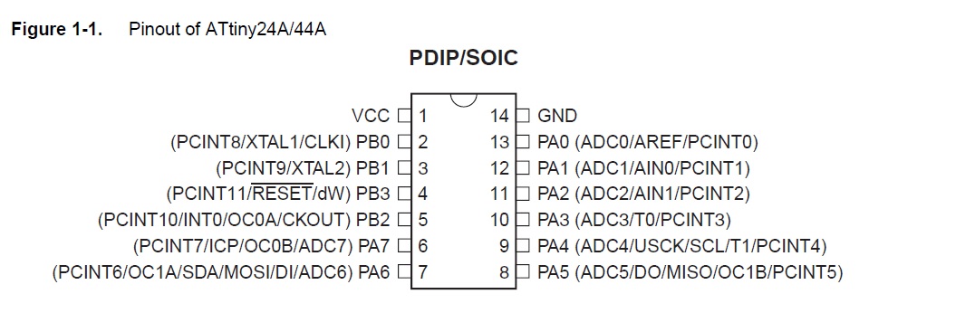
Here is a picture of the ATtiny pins
Ports and pins
What I understand at this point, is that the ATtiny 44 has 2 ports (Port A and Port B).Here are the port descriptions from the datasheet
"Port A is a 8-bit bi-directional I/O port* with internal pull-up resistors** (selected for each bit). The Port A output buffers have symmetrical drive characteristics with both high sink and source capability. As inputs, Port A pins that are externally pulled low will source current if the pull-up resistors are activated. The Port A pins are tri-stated when a reset condition becomes active, even if the clock is not running. Port A has alternate functions as analog inputs for the ADC, analog comparator, timer/counter, SPI and pin change interrupt." (attiny datasheet, pin configuration (pp.2))
"Port B is a 4-bit bi-directional I/O port with internal pull-up resistors (selected for each bit). The Port B output buffers have symmetrical drive characteristics with both high sink and source capability except PB3 which has the RESET capability. To use pin PB3 as an I/O pin, instead of RESET pin, program (‘0’) RSTDISBL fuse. As inputs, Port B pins that are externally pulled low will source current if the pull-up resistors are activated. The Port B pins are tri-stated when a reset condition becomes active, even if the clock is not running." (attiny datasheet, pin configuration (pp.3))
* input/output (I/O) ports. I/O ports allow for connections to hardware. The ports are associated with copper circuits and memory ranges that allow the communication of data between the CPU, RAM, and the ports themselves. Common I/O ports include USB and FireWire, as well as SCSI, audio connections, MIDI, and RG-6 coaxial ports. (Pearson certification, IO ports and devices)
** pull-up resistor: "Let’s say you have an microcontroller with one pin configured as an input. If there is nothing connected to the pin and your program reads the state of the pin, will it be high (pulled to VCC) or low (pulled to ground)? It is difficult to tell. This phenomena is referred to as floating. To prevent this unknown state, a pull-up or pull-down resistor will ensure that the pin is in either a high or low state, while also using a low amount of current."(Sparkfun, Pull-Up resistors)
- Port A has 8 pins (PA0-PA7 in the picture)
- Port B has 4 pins (PB0-PB3 in the picture)
- GND is the ground pin
- VCC is the supply voltage pin.
Configuring the pins
Each port pin consists of three register bits: DDxn, PORTxn, and PINxn. The DDxn bits are accessed at the DDRx I/O address, the PORTxn bits at the PORTx I/O address, and the PINxn bits at the PINx I/O address. The DDxn bit in the DDRx Register selects the direction of this pin.(attiny datasheet, (pp. 53-->))
- If DDxn is written logic one, Pxn is configured as an output pin.
- If DDxn is written logic zero, Pxn is configured as an input pin.
"If PORTxn is written logic one when the pin is configured as an input pin, the pull-up resistor is activated. To switch the pull-up resistor off, PORTxn has to be written logic zero or the pin has to be configured as an output pin. The port pins are tri-stated when reset condition becomes active, even if no clocks are running."
"If PORTxn is written logic one when the pin is configured as an output pin, the port pin is driven high (one). If PORTxn is written logic zero when the pin is configured as an output pin, the port pin is driven low (zero)."
I think that chapter 10 of the datasheet (I/O ports) will be most useful! It provides the info on how to cofigure pins, toggle them, switch between input and output, reading pin values, and gives some programming examples! We shall see how this project develops :)
Programming the board
We started this weeks assignment with the help of our local instructor, Juha-Pekka. To be able to do this, we first all downloaded and installed Atmel Studio 7.0.
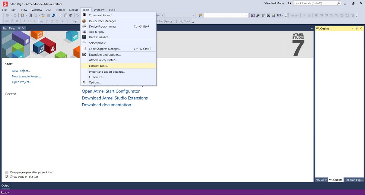
When Atmel studio was installed, we added avrdude to Atmel Studio from "tools -> external tools". We had already installed AVRDude on week 5, so it was already on our computer.
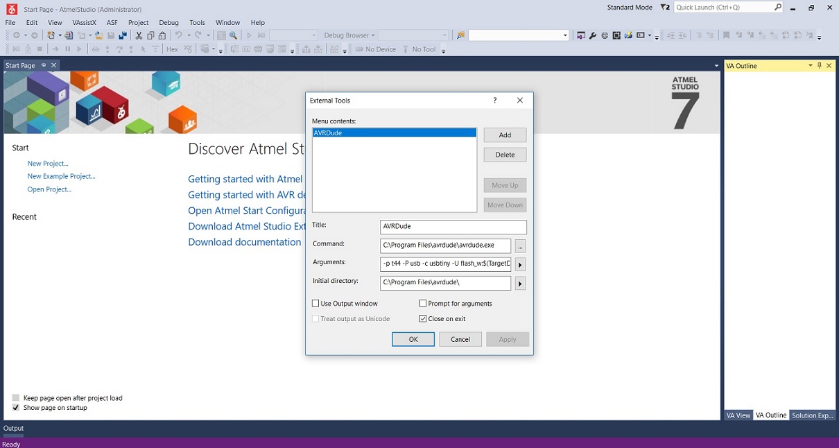
We modified the command, arguments and initial directory:
Command --> C:\Program Files\avrdude\avrdude.exe
Arguments --> -p t44 usb -c usbtiny -U flash:w:$(TargetDir)$(TargetName).hex:i
Initial directory --> C:\Program files\avrdude
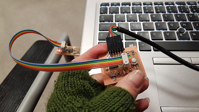
Before proceeding, we also attached our own programmer and board to the computer
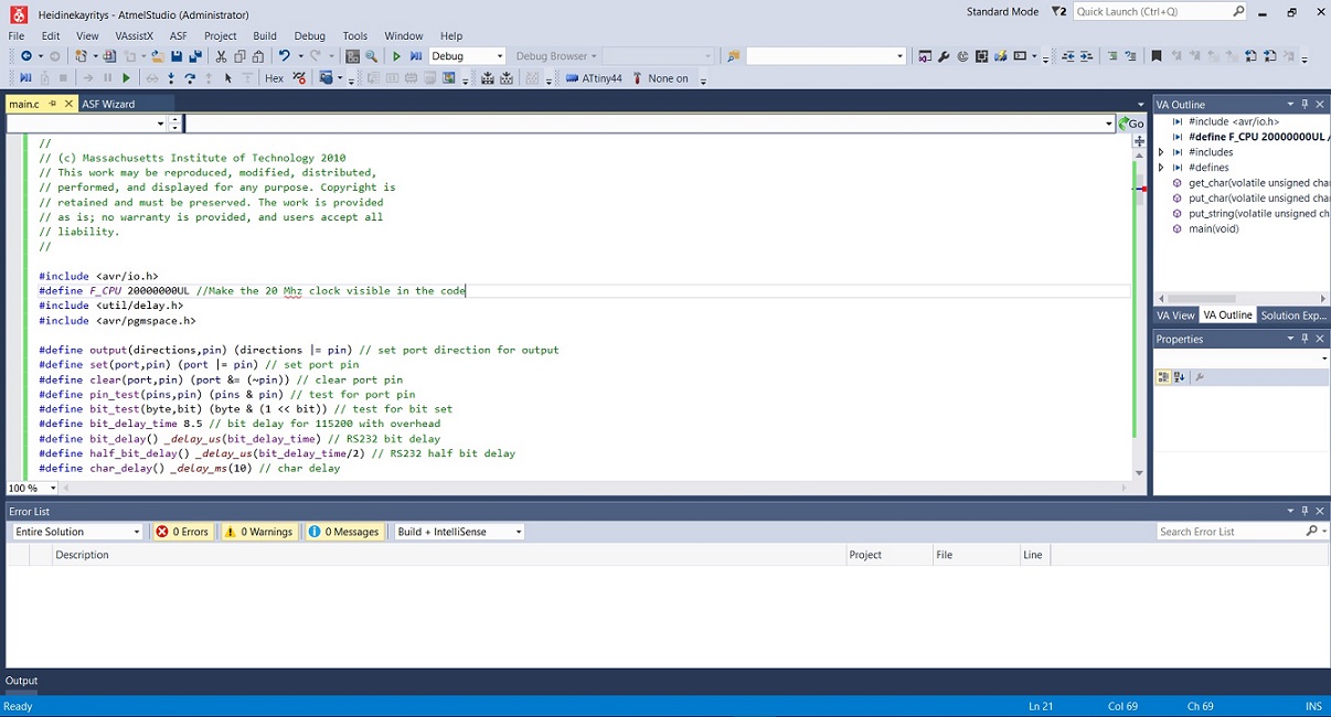
We started a new C executable project
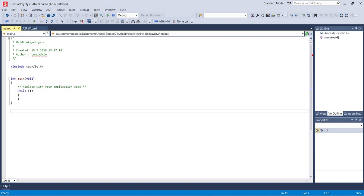
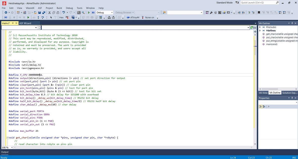
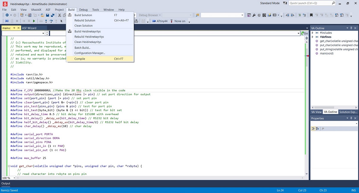
And switched the code to Neil's hello world code, and made the 20mhz clock visible in it.
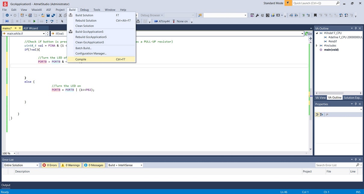
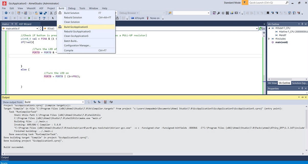
Selected to compile the code
I got some errors in the first compile
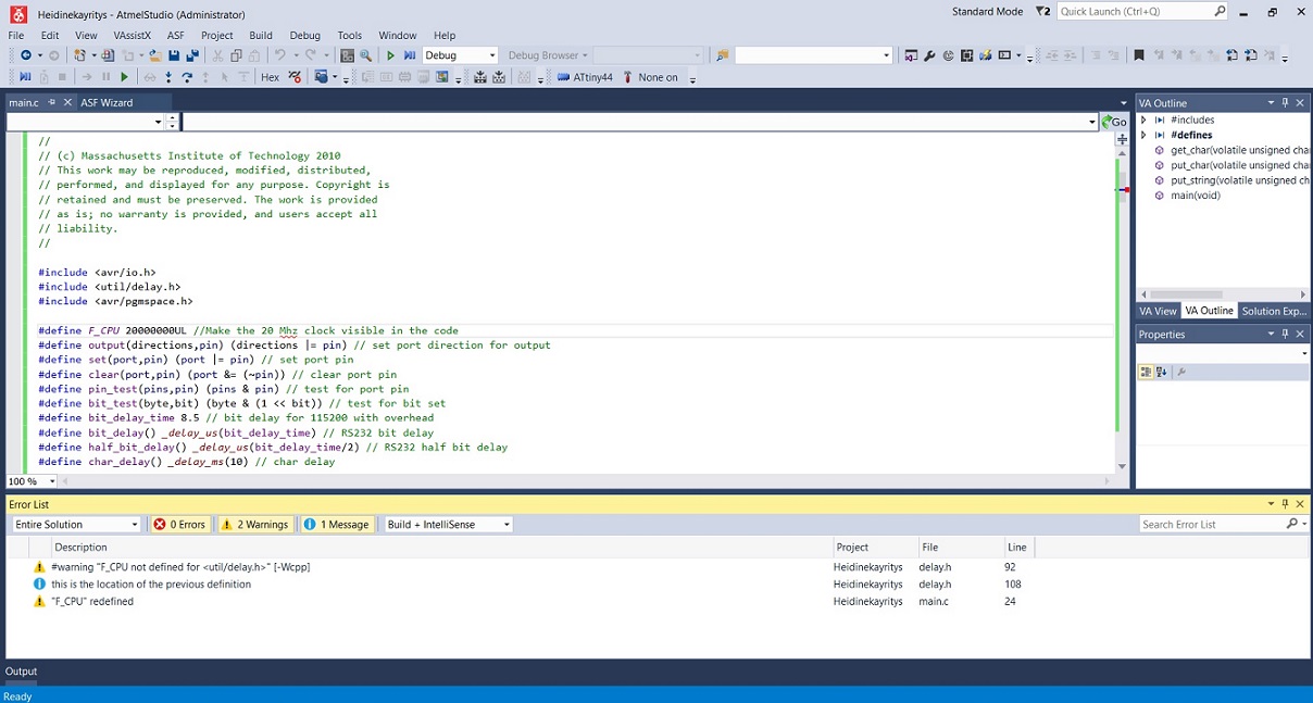
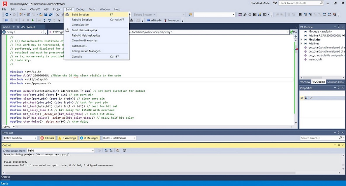
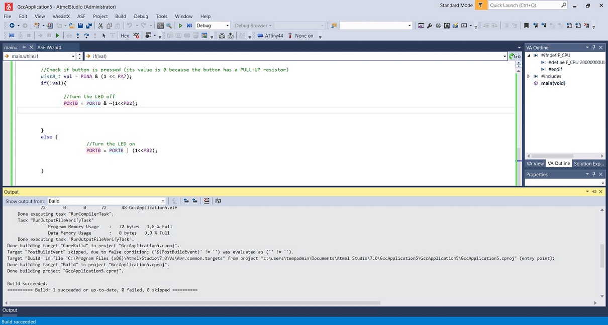
So I switched the location of the clock code which seemed to do the trick and the compile went through
Next we built the solution
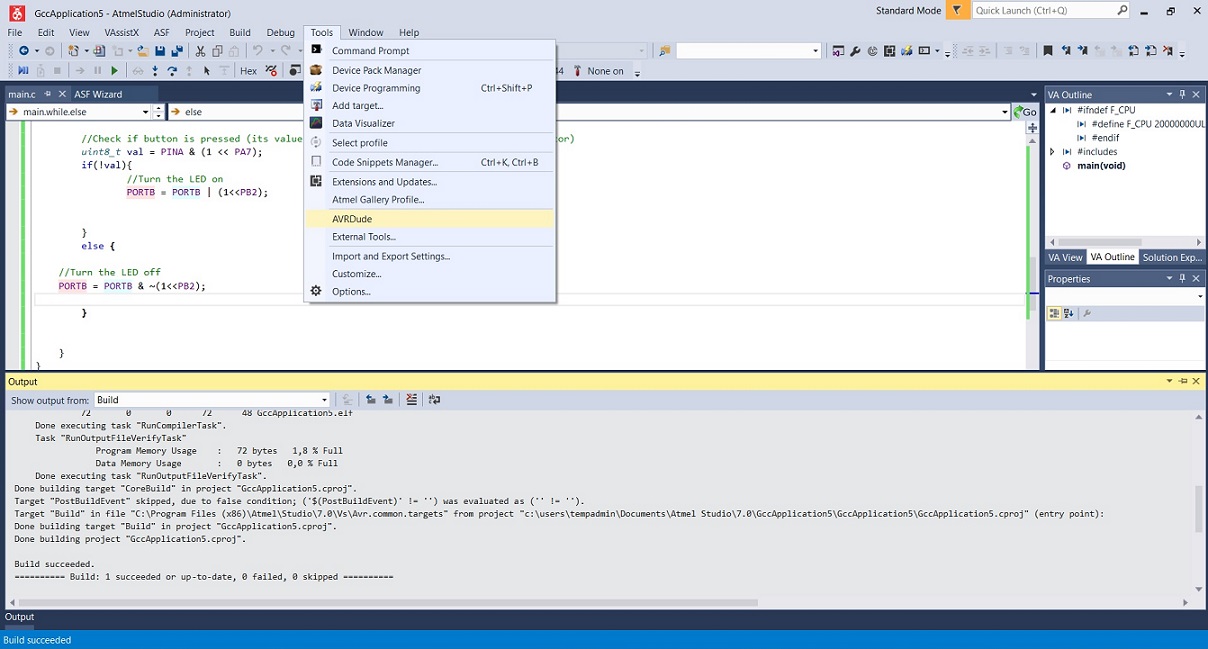
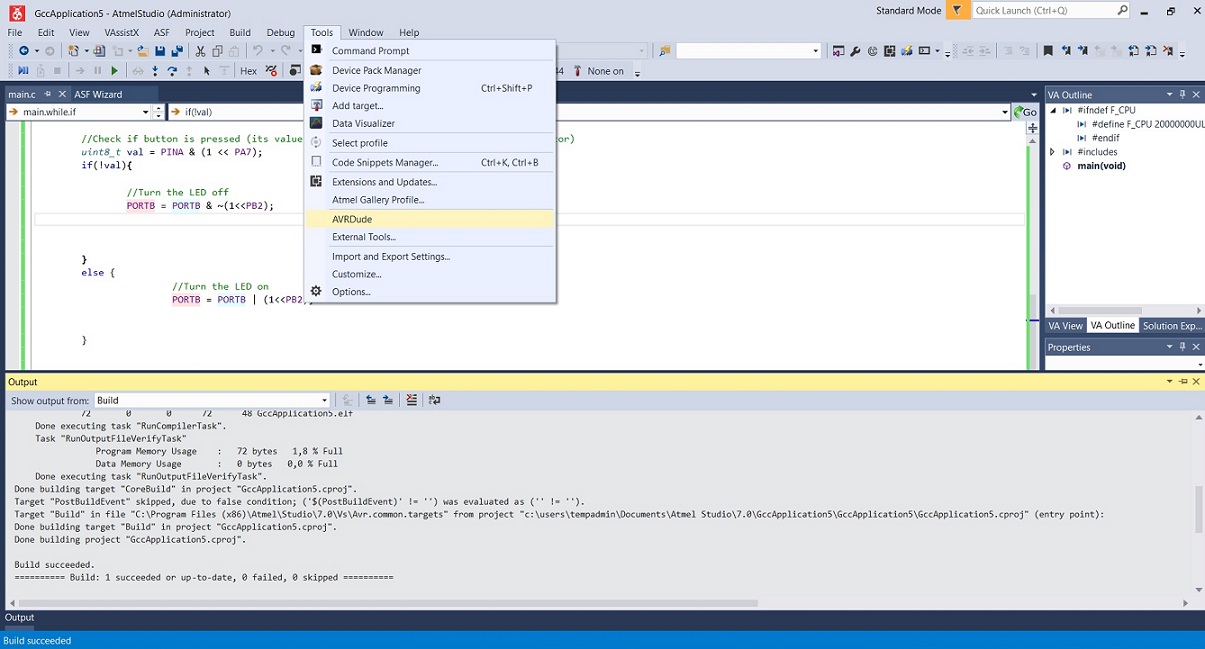
And selected tools --> AVR dude to program it to the Attiny. Unfortunately, my code did not work, AVR dude could not find the USB device. That is because my programmer did not work.
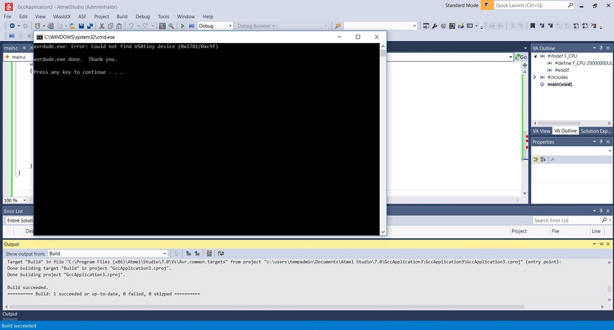
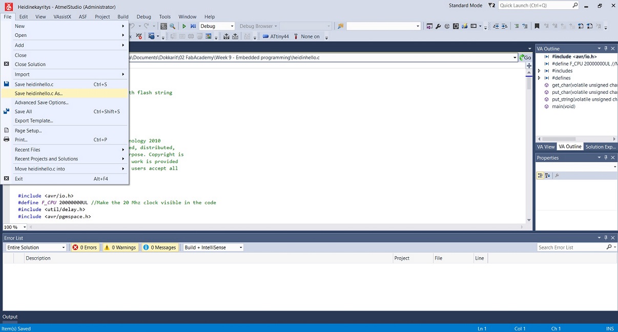
Instead I proceeded to save the code to my computer and pretty much called it a day.
The next day, I troubleshooted my board and my programmer with the help of Antti (documented in W7). I also reprogrammed so that it worked, and started to work on this weeks assignment.
It was time to try and add some different code to our board, using Atmel studio. I think we all went with trying to make the led blink by pressing the button on the board.
For this Juha-Pekka suggested Ivan's "blink_button.c" code from last year, which I proceeded to copy and paste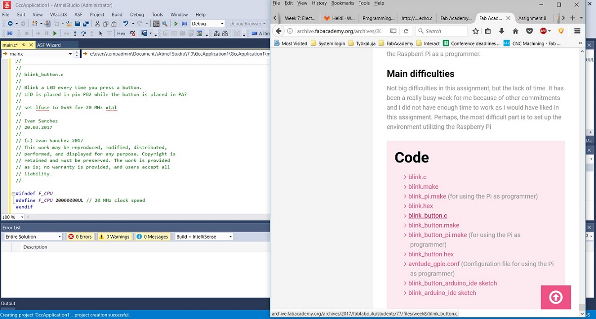
I compiled the solution without errors
Built the solution
Ran it through AVR dude
And voila - the led lights up when the button is pressed. Fancy indeed.
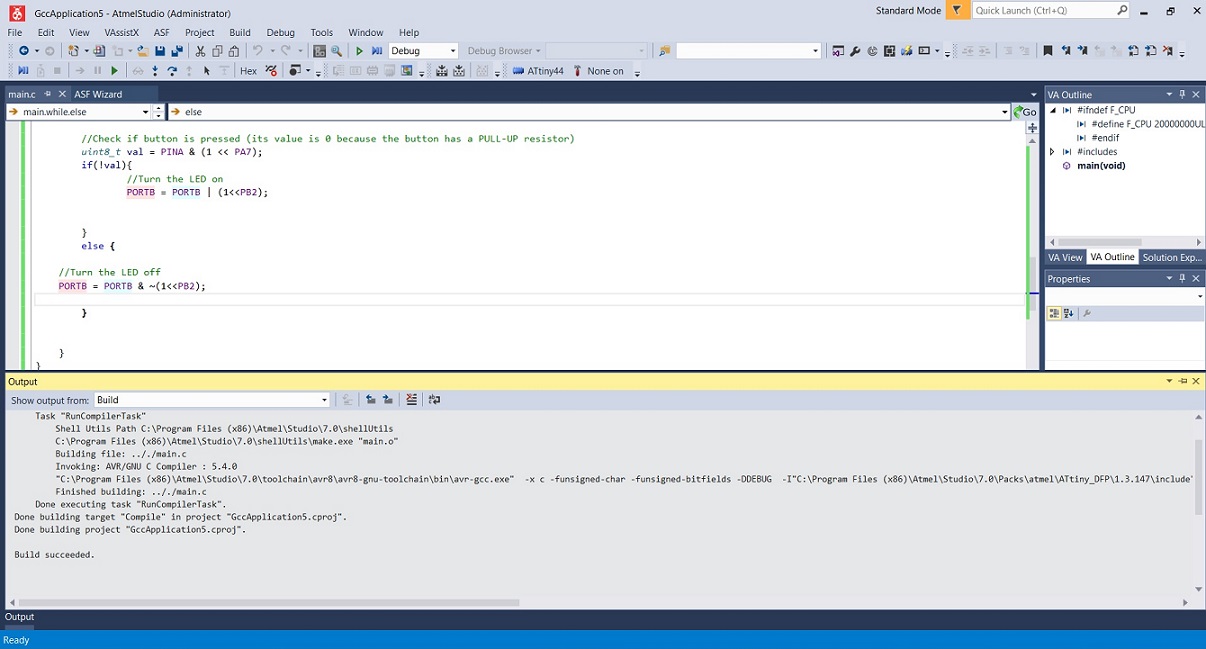
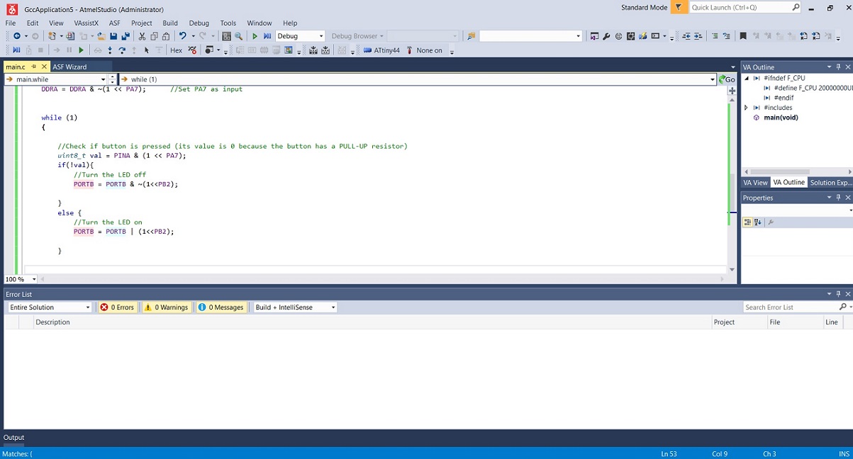
Next we were advised to try and get the led/button combo to add somehow differently. The easiest way to do this,
was to change the code in a way, that the light turns off when pushing the button (instead of turning on)
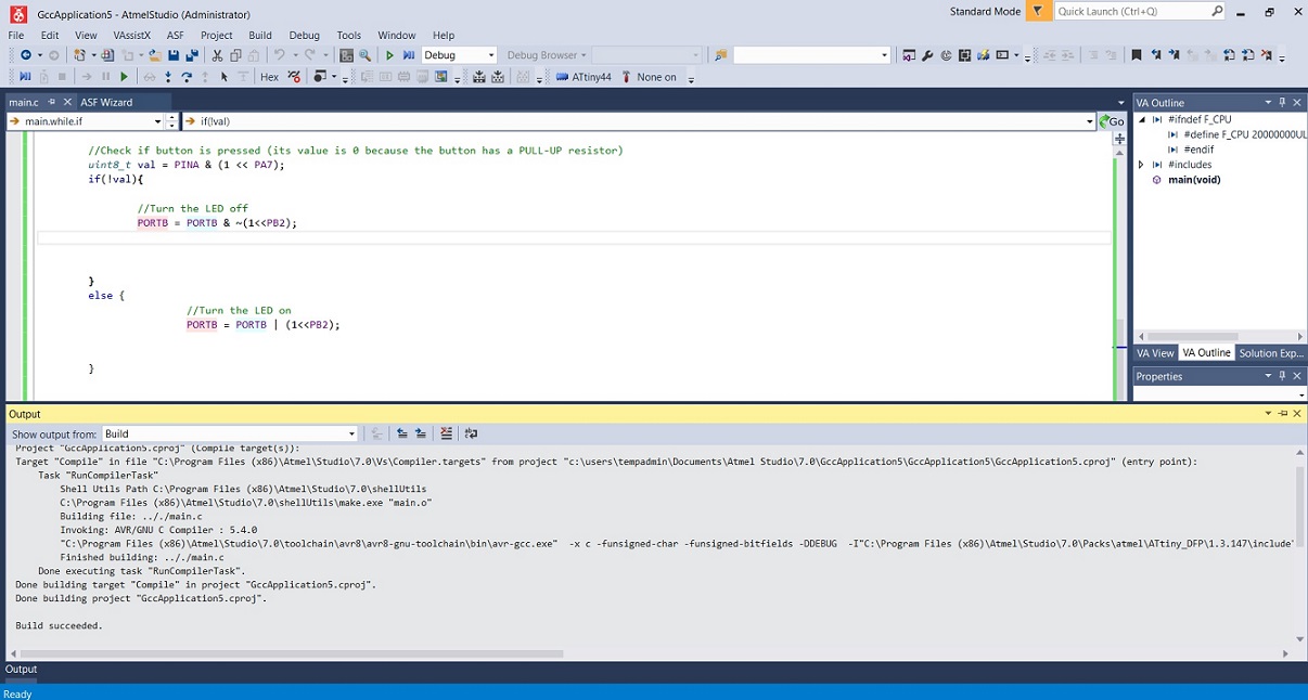
After doing this, I compiled the modified code
Thankfully without errors
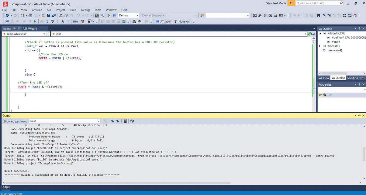
Built the modified code
Without errors
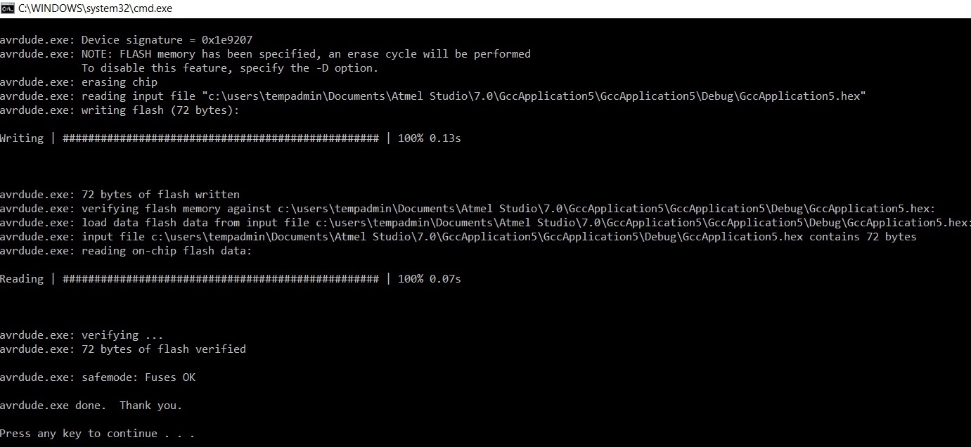
And again used AVR dude to carry the code to the board
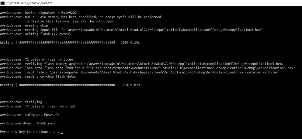
Here is the superfancy solution
Here are the files used
HelloWorld code, clock added:
- Neil's hello world C code with the clock added.
- Neil's hello world code with the clock added - Makefile.
- Neil's hello world code with the clock added - Hexfile.
Ivan's original blink button:
- Ivan's blink button - C code
- Ivan's blink button - Makefile
- Ivan's blink button - Hexfile
Ivan's blink button, reversed:
- Ivan's blink button, reversed - C code
- Ivan's blink button, reversed - Makefile
- Ivan's blink button, reversed- Hexfile
Problems had, lessons learned, questions that remain
Datasheet
- This was really complicated, a lot to take in. A lot to learn still!
- No real problems here. Basically just learned another way to program the board this week. I only had time to get to know Atmel studio but I liked it.
- I had somehow a really really hard time figuring out how to transport the code from the computer to my board. I have coded before with C++ and Java, and albeit it has been over 10 years since I did it for a job, this is pretty embarrassing. I was a programmer for about 2 years after the polytechnic before moving on to the uni - but the job only entailed coding, compiling and building something according to instruction, and I never worked with the hardware, or saw any of my own code in action. So this week was an eye opener for sure
- So - For some weird reason, having built my own programmer on week 5, and having tried to use it already on week 7, here I was, using Atmel studio, and trying to magically transfer the code from the computer to the board without my programmer. I was sitting there all ready to code the s**t of that led, having only attached my board to the computer with a USB/FTDI cable, wondering where I went wrong. For atleast 30 minutes. My local instructor Juha-Pekka corrected me on this, and my bruised ego was healed a bit later having learned that some of the other FabStudents in our lab had done the same thing at first as well
Copyright © Heidi Hartikainen 2018
Template copyright ©Blackrock Digital LLC 2013-2018

This work is licensed under a Creative Commons Attribution-NonCommercial-ShareAlike 4.0 International License.