Designing something big
For this week, I really wanted to learn how to make furniture using fusion 360, especially how to create joints. And I wanted to make something big. So I googled for CNC furniture ideas and found plenty. I finally picked a YouTube flatpack Bookshelf tutorial by Patric Rainsberry as it seemed to be really detailed, and explained all steps well.
The video also had accompanying textual instructions on Instructables.
Before I got started, I downloaded the Dogbone add-in and the nester add-in that are used in the video, I created folders for them in the %appdata%\Autodesk\Autodesk Fusion 360\API\AddIns folder (In my case C:\Users\hhartika\AppData\Roaming\Autodesk\Autodesk Fusion 360\API\AddIns\), and included all the files of the Add-In there, as advised in this helpful tutorial on how to install fusion360 sample scripts and add-ins.
When I opened up Fusion, I first created a project called "CNC furniture", and started a blank sketch there. The first thing to do, was to click on "modify --> change parameters" to create some parameters for the design.

I defined parameters for the height (711mm), the width (813mmm) and the depth (356mm) of the bookshelf, and then some more specific parameters.
- "OSB" specifies the thickness of the material we use in FabLab oulu, it's thickness is 11mm
- "Cutter" specifies the size of the tool used to cut out the design. In FabLab Oulu we use a flatheaded 8mm tool (I added a parameter for that, but did not end up having to use it)
- "Shelf" specifies the position of the shelf from the bottom of the bookshelf, 305mm
- "Kick" meaning the kickboard in the bottom, specifies how high the kickboard will be, 51mm
- "Tab" specifies the width of the tabs that will be used to connect the parts together, 76mm (the tab depth will be "osb")
- "BlindTab" specifies the depth of the tab that you do not want to go all the way but stay hidden (the tab width will be "Tab")
- "blindPocket" is the corresponding side on the other piece, the hole where blindTab will be inserted to. It is a bit deeper than the tab so that it is not too snug a fit
Using these kinds of parameters when designing is useful, as it will make it much easier later on to change dimensions of the furniture later on (for example if your material changes, you want to make it higher etc). Later on, I could then do my modifications in one place, and those changes I make would be reflected everywhere.
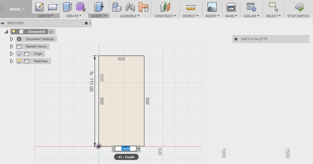
THe next thing I did, was draw a two point rectangle on my sketch representing one side of my bookshelf - specifying the Height (711mm), and the depth (356mm) by leveraging the parameters I just created.
Then I continued to draw some more rectangles on top of the first one.
- One to represents the top of the bookshelf
- One to represent the back of the bookshelf
- Two to represent the shelves it will have
- And a small one in the bottom, to represent the kickboard under the shelves.
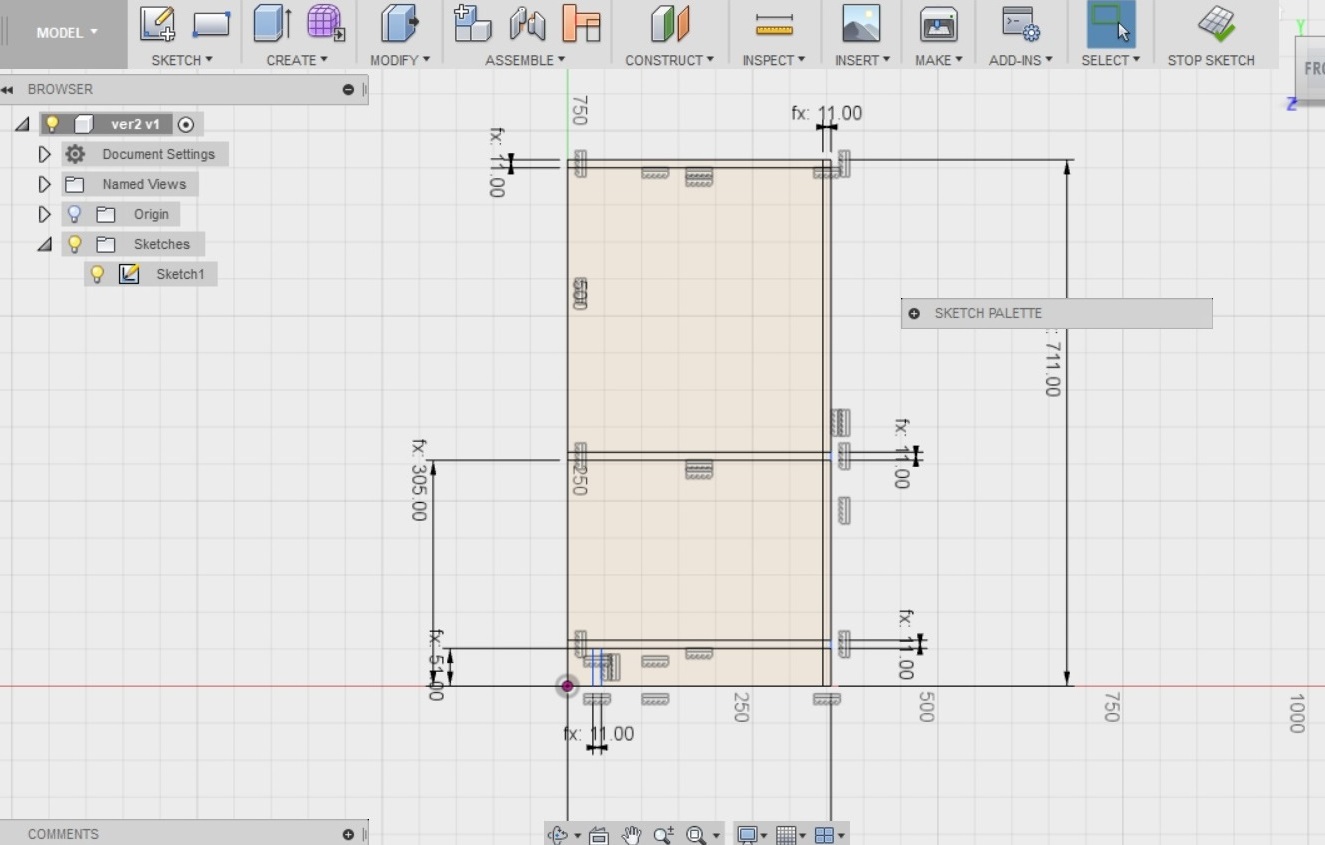
Here I have also continues to leverage the parameters created.
- The depth of the kickboard, the backboard, the top, the shelves are all "osb" (11mm).
- The kickboard height is "kick" (51mm)
- And the shelf is positioned "shelf" amount from the ground (305mm)
---------------------
After these were all done, it was time to start "pulling out" or extruding the shelves, the kick, the back etc from the skech.
- I selected the Create --> Extrude tool from the top menu
- I selected the top two rectanges in the sketch that represent the top of the bookshelf
- I leveraged the "Width" value by typing it into extrude depth, to get the top of the bookshelf to be as wide as I wanted it to be.
- Select “New Body”, press OK
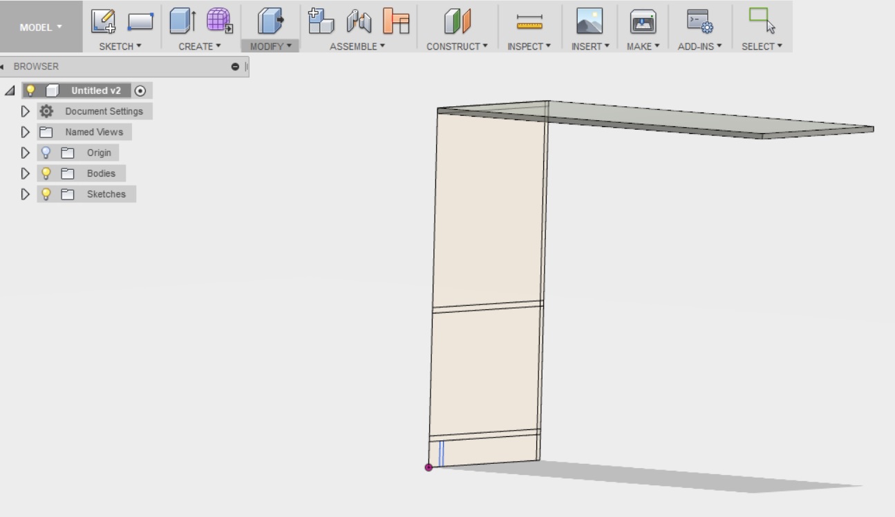
Then I selected create --> Extrude to pull out the side of the bookshelf under the top. This was done by selecting all of the 12 small rectangles visible in the sketch under the top of the bookshellf and typing "osb" into the value for the extrude depth. I selected “New Body”, and pressed OK
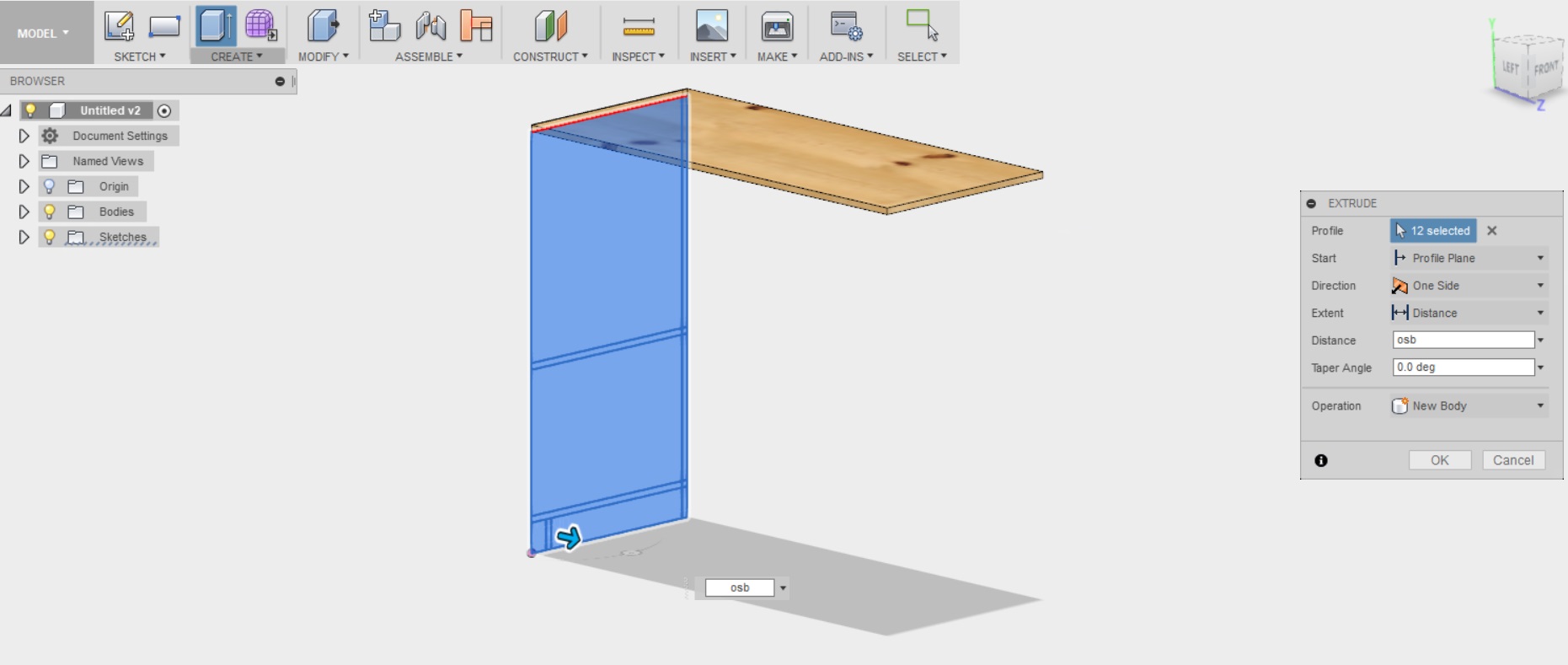
It was explained in the tutorial, that here selecting always "new body" is important, as by default the program wants to join different extrusions together to form a solid piece. When building the bookshelf we however want to separate each part we build from each other. You can not pull out a solid bookshelf from a CNC machine.
---------------------
When the top and the side were ready, the tutorial advised me to build a mid plane. Apparently, this is a handy way to specify the center of the model, and using it I can later mirror components to the other side of the design, without having to "build" or draw them.
To build the midplane, I chose Construct --> Midplane from the above menu. Then I selected the two outer sides/faces of the top of the bookshelf and clicked OK.
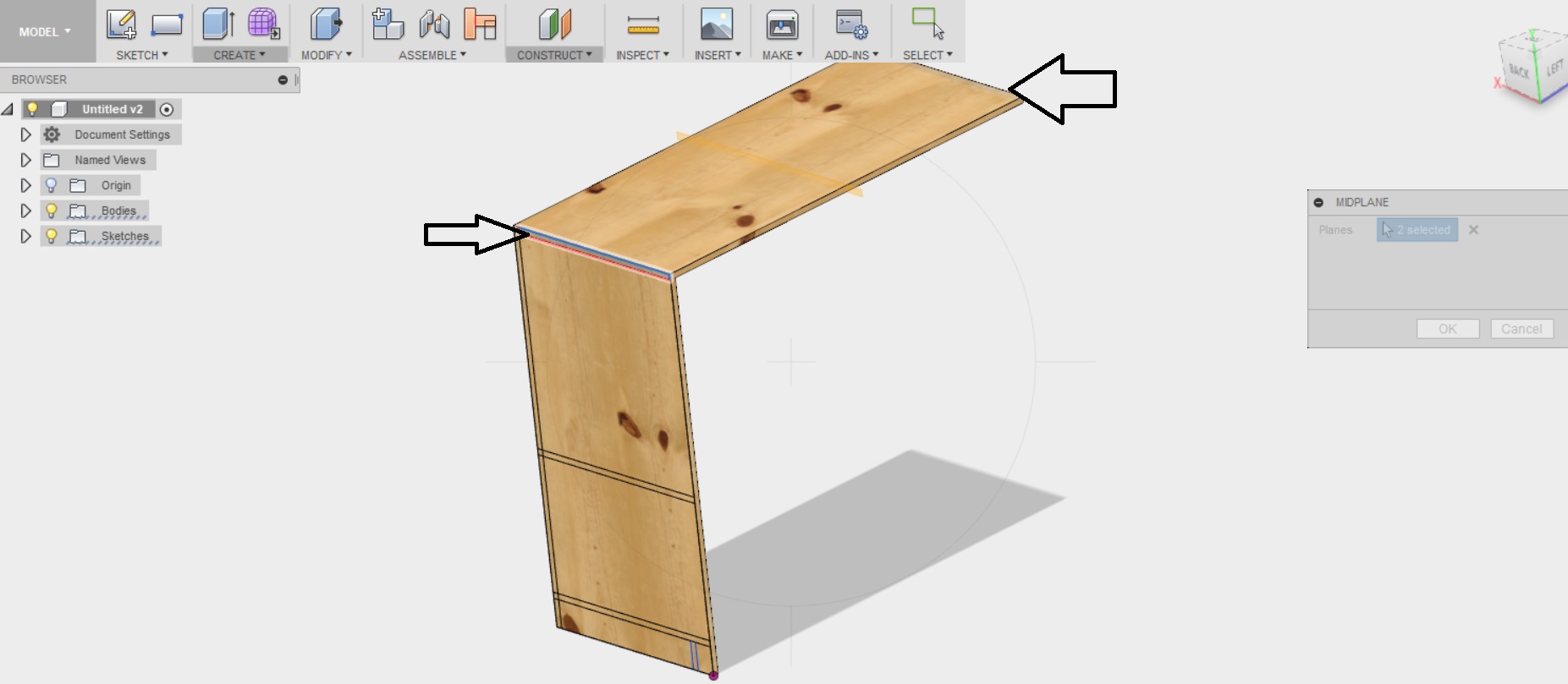
This mirroring function was put to test right away, as the tutorial advised me to now try and mirror the left hand side of the bookshelf, to create the other side.
I selected Create --> Mirror from the menu above, and selected the pattern to mirror to be bodies. I clicked on the side piece of the shelf to select it as the side to be mirrored, and then I selected the midplane from the tree on the left as the plane to mirror on.
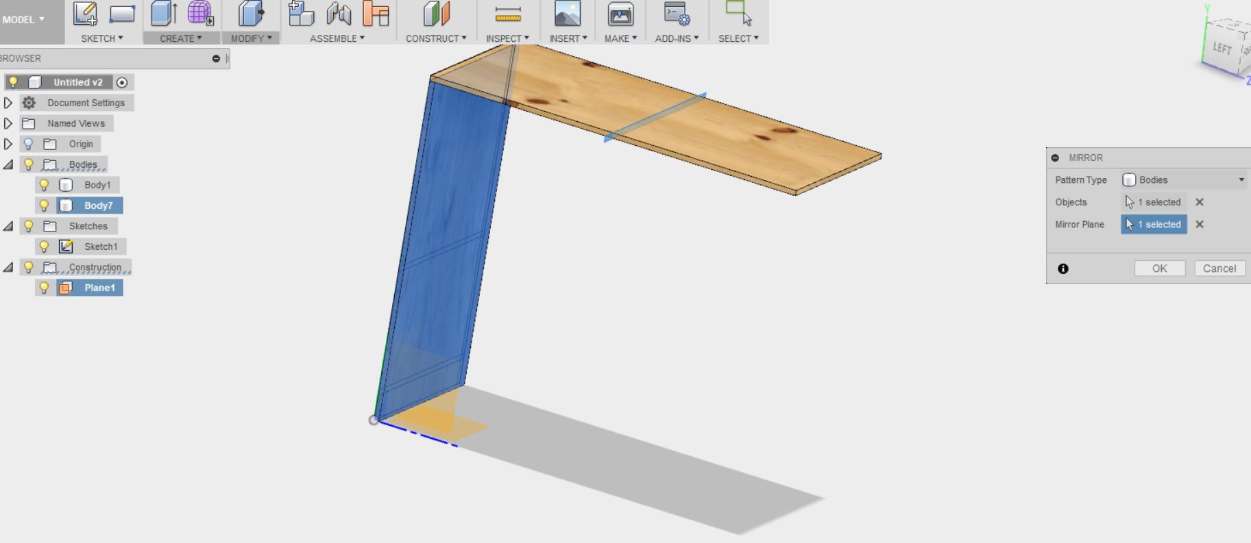
Clicked OK, and voila! I have the other side of the bookshelf!
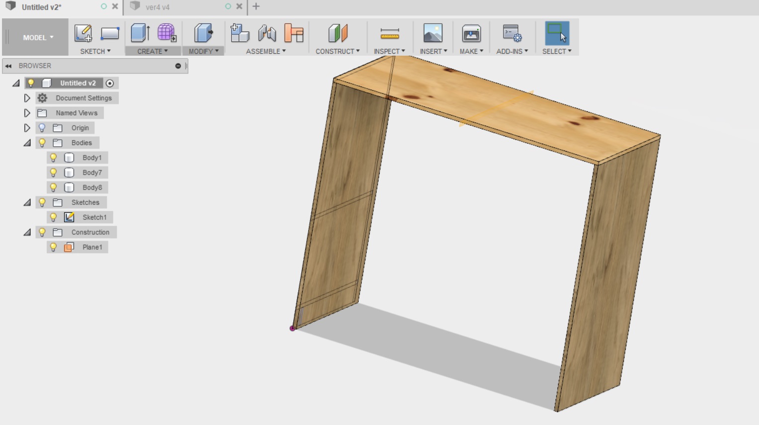
---------------------
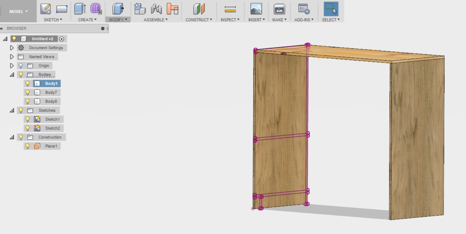
Next the tutorial advised me that I should create a projected sketch on the inner face of the "left side" of the bookshelf. THis is just to project the sketch from the other side, so that we can create the shelves (we want the shelves to start from the inner edge, not the outer edge)
To do this, I selected Sketch --> Create Sketch from the menu above. Then I selected the inside face of the bookshelf and the lightbulb next to sketch 1 (located at the tree on the left). Then I select Sketch --> Project Include/Project, selected all of the lines from Sketch 1, and clicked stop skech from the menu above.
---------------------
Next it was time to create the rest of the components, the backpiece, the two shelves, and the kickboard.
I started with the backpiece as was adviced in the tutorial.
I selexted all of the small rectangles (5) in the sketch that make up the backboard, I selected the distance by clicking the inside face of the other side piece of the bookshelf. And I remembered to select "new body", and not join!!
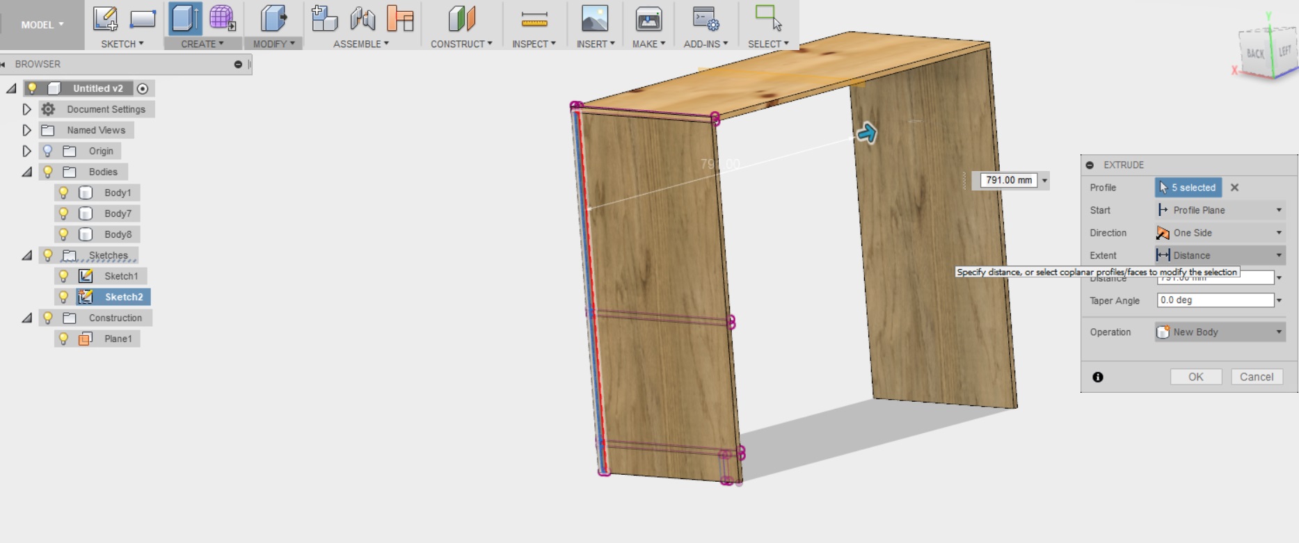
This was the result

Here is how it looked like then
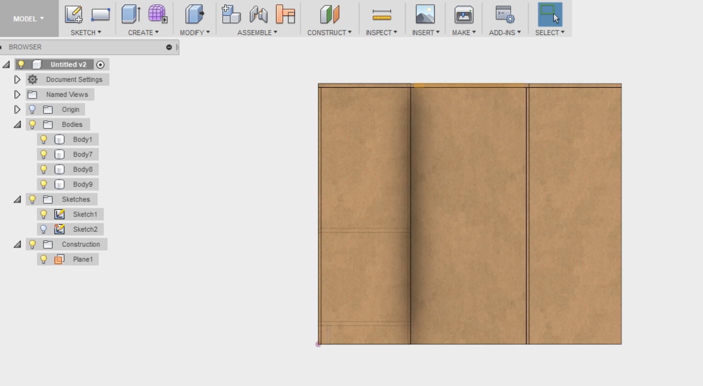
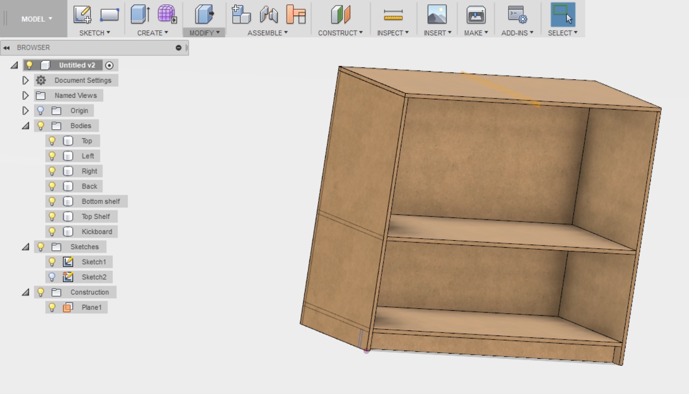
I repeated the process exactly the same for the two shelves and the kickboard, and this is the result. Note that I have also been playing around with the tool Modify --> Appearance from the top menu, to see what the shelf might actually look like when I cut it
---------------------
Next it was time to create tabs for the joints. The tutorial advised me through this with more ease than I could have imagined. We started with the kickplate.
- I selected sketch --> create sketch and selected the front face of the kickplate.
- I draw two two point rectangles, one on the side of the kickboard, and one above it.
- I draw a line at the center of both rectangles, selected this line, and defined it to be a constructio line
- I dimensioned the sketch, leveraging again some parameters I defined earlier, mainly tab and osb. I also used width to position the upper tab in the correct place.
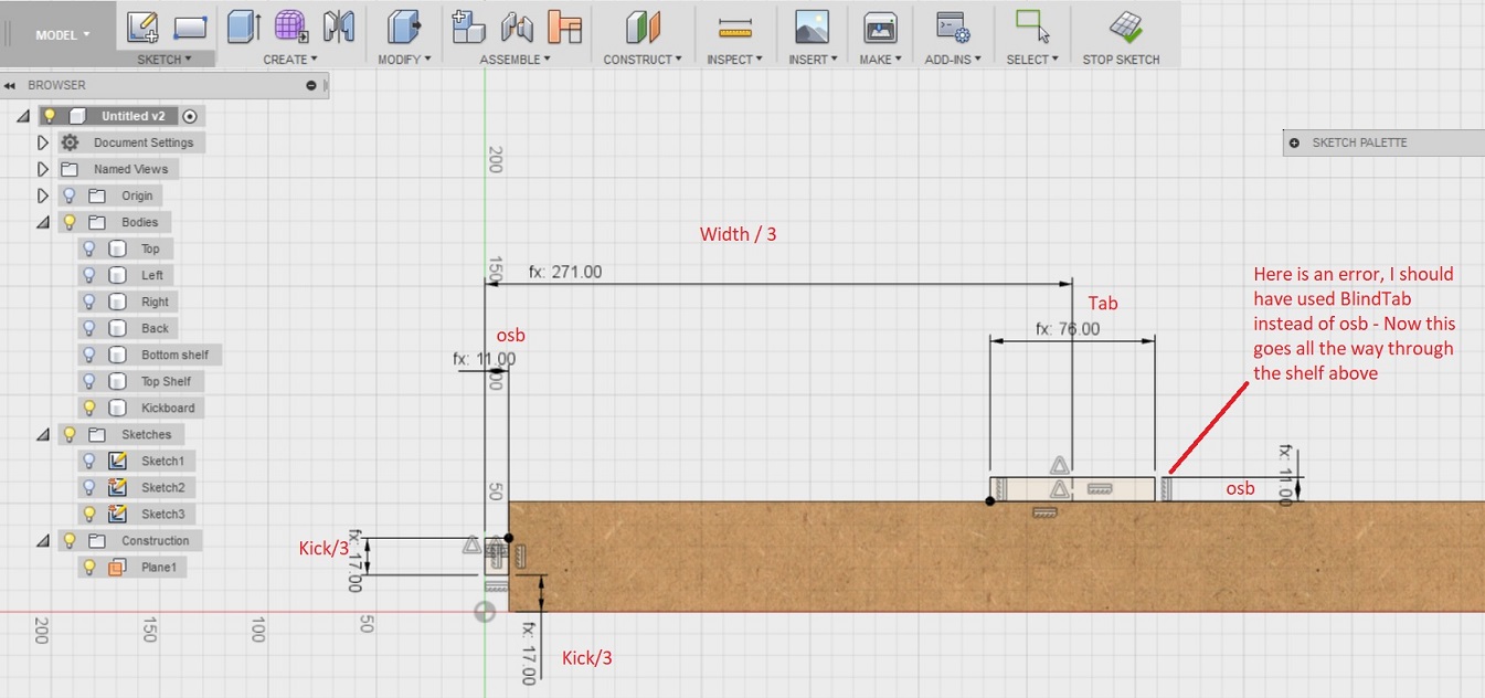
Next I selected Stop Skech from the menu above, selected create --> Extrude. Then I clicked on the "backside" of the kickboard to extrude to it, and selected "join"
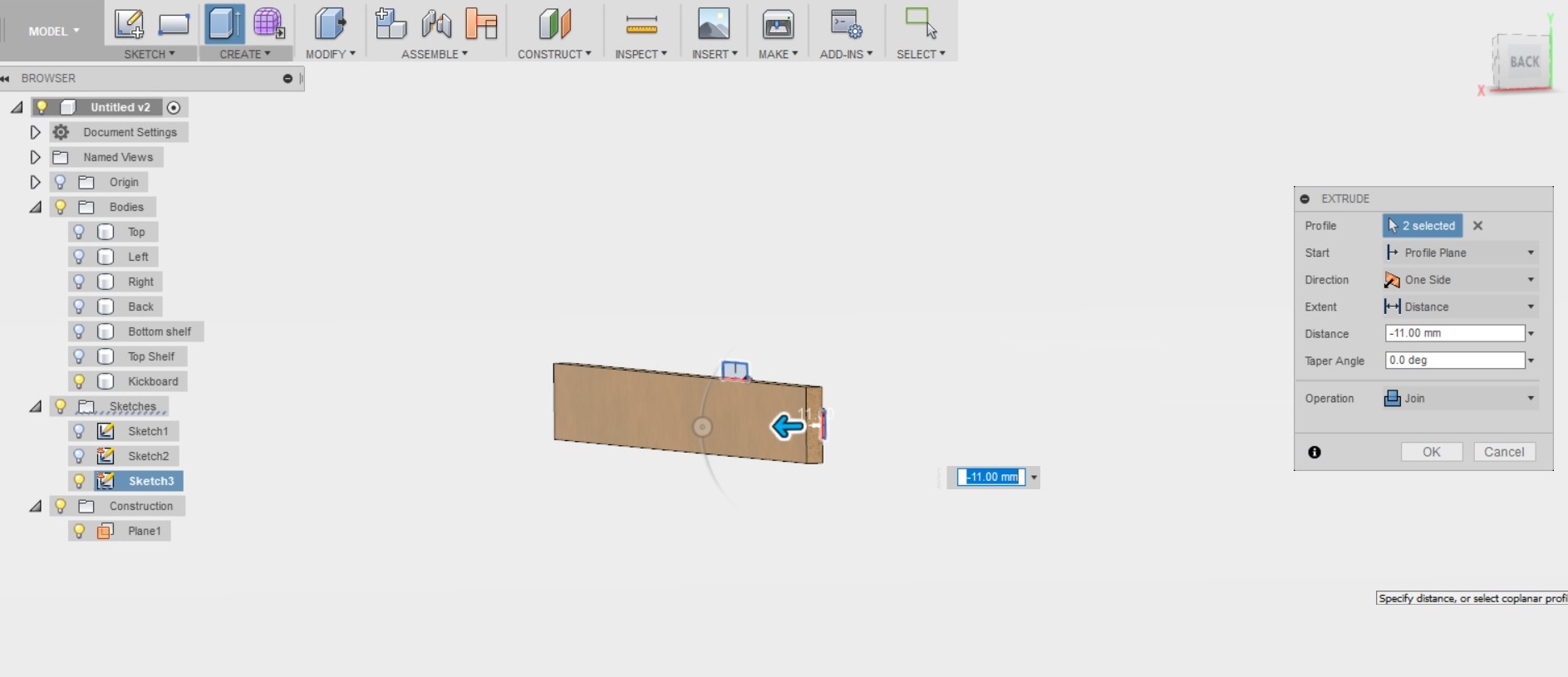
The result looks like this
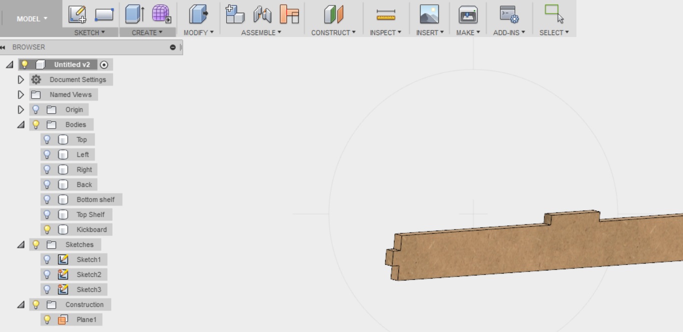
These tabs were then mirrored to the other side of the kickboard as well
- I selected Create --> Mirror from the menu above
- I set the pattern type to faces
- And selected the side faces of the tabs as advised (3 on each tab, 6 in total).
- Then I selected to mirror on the midplane that we had previously defined
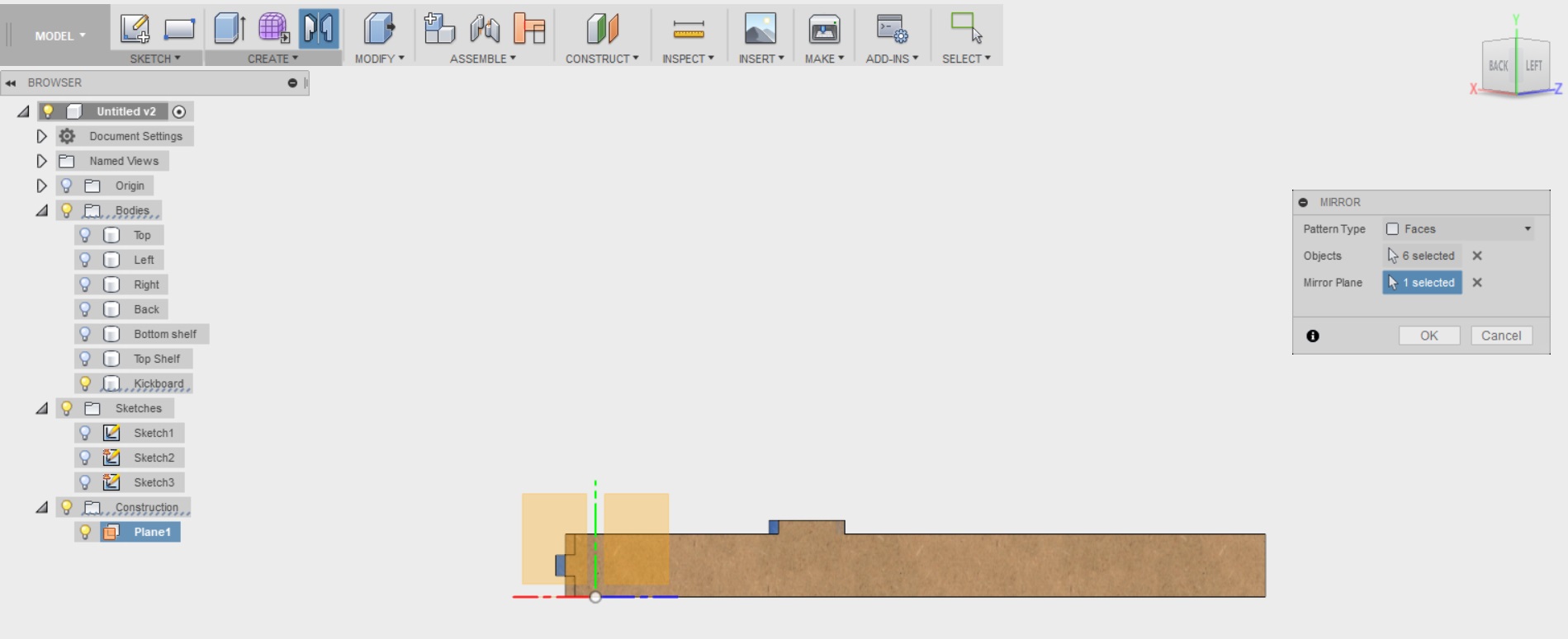
Then I clicked OK.This is what the kickboard looked like finished
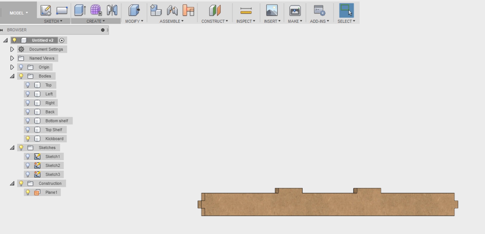
---------------------
Next I hid the kickboard from the design (by clicking the lightbulb next to it on the tree), and created tabs for the shelves.
I started with the bottom shelf as advised
- Again, I selected sketch --> Create Sketch from the top menu.
- I selected the top face of the bottom shelf
- I draw 3 two point rectangles, one on the top, and two on the side.
- I drew lines at the midpoints of each rectangle, and selected them by right click to be construction lines
- I dimensioned the sketch, leveraging again some parameters I defined earlier, mainly tab and osb. I also used width to position the upper tab in the correct place, and depth to position the side tabs.
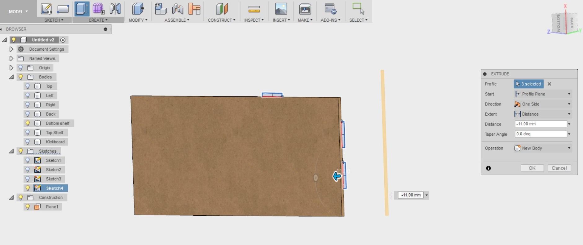
Then I pressed Stop sketch from the upper menu, selected Create --> Extrude, picked the three profiles, and clicked on the bottom face of the shelf to extrude there. This time I was advised to select "new body" for operation again. Then I pressed OK. This is the result
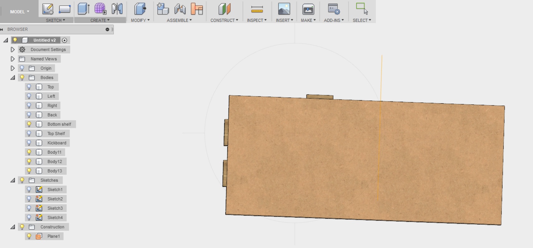
These tabs are again mirrored to the other side of the shelf.
- I selected create --> Mirror from the menu above
- I set the pattern type to bodies
- Selected the three tabs/bodies i just created
- And I selected the mirror plane
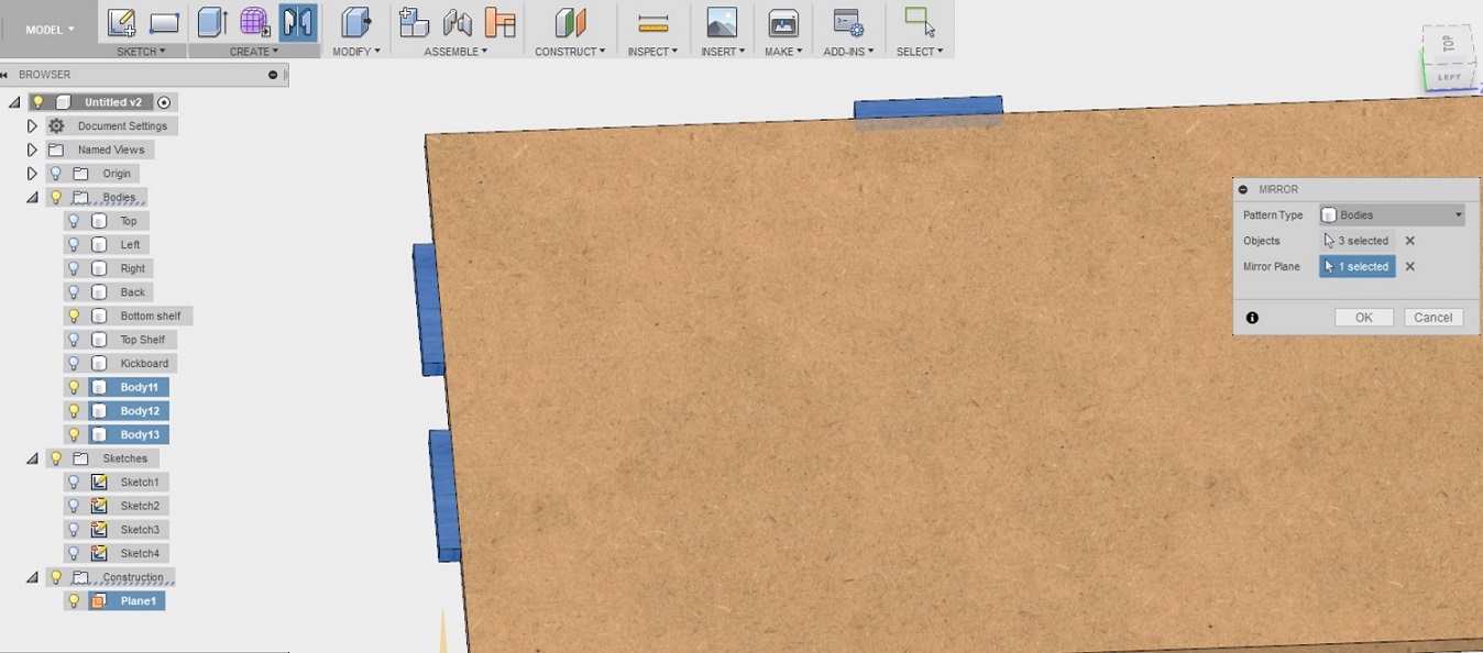
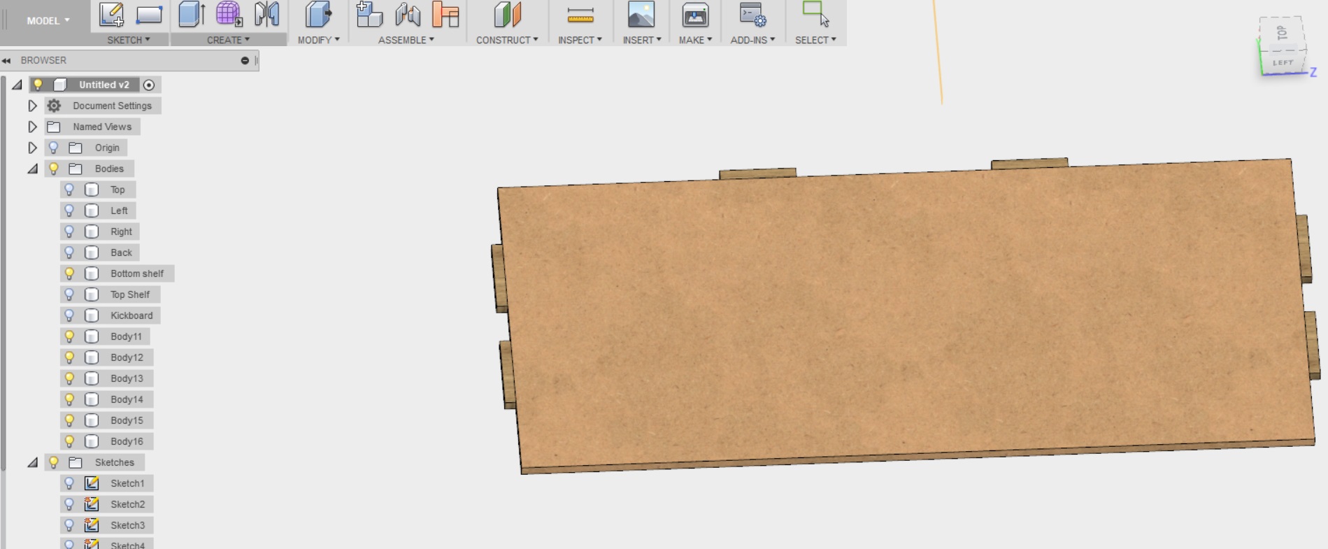
Then I clicked OK. This is what the mirrored shelf looked like finished
---------------------
Next the tutorial taught me how to mirror the tabs to the top shelf. So I did not have to recreate them.
- I clicked on the lightbulb on the tree on the left, next to the topshelf to make it visible
- I selected construct --> Midplane from the menu above
- I selected the top of the bottom shelf, and the bottom of the top shelf and clicked OK
- I selected create --> Mirror
- I set the pattern type to bodies
- I selected the 6 tabs/bodies I wanted to mirror to the upper shelf
- And finally selected the newly created plane as the one to mirror on.
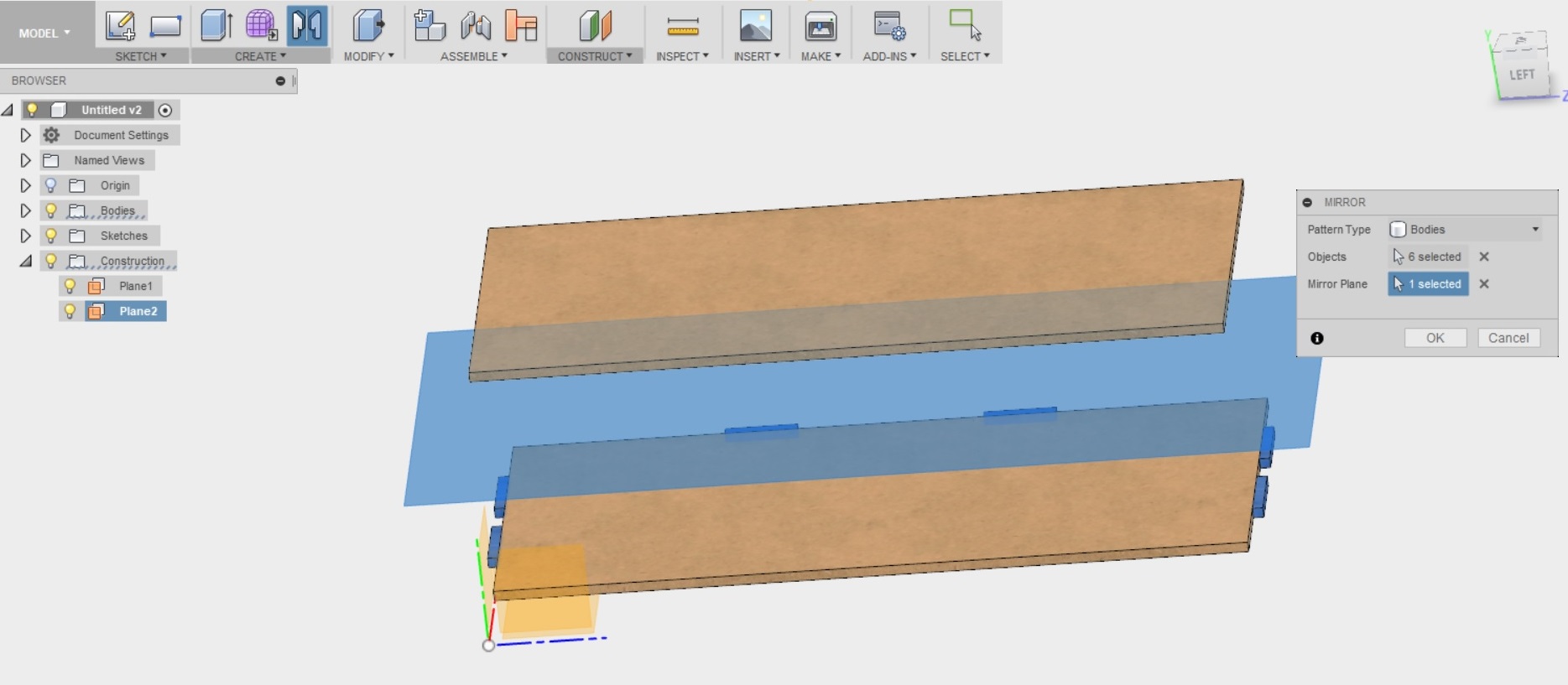
When I clicked OK, this was the result.
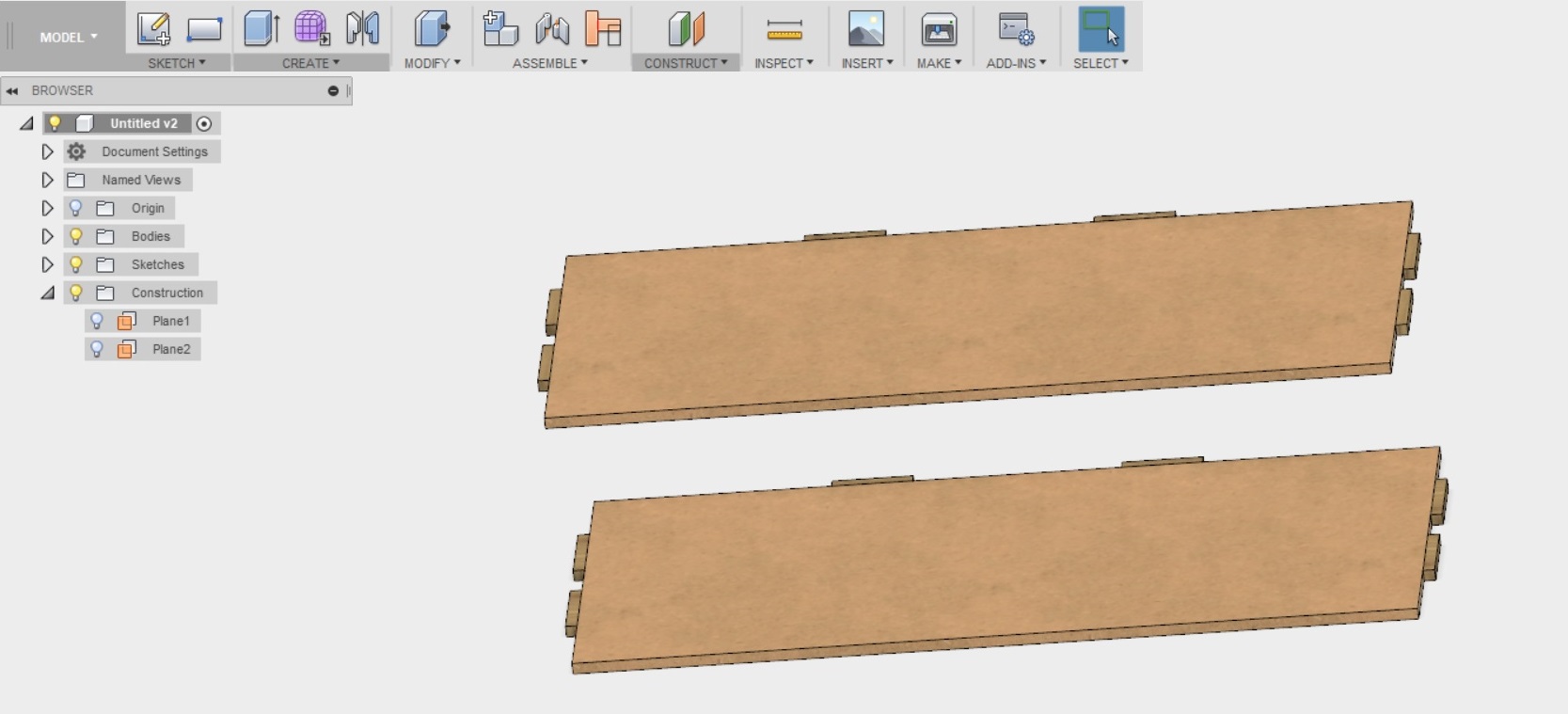
---------------------
Next the tabs were joined to the shelves, in order to make them into single parts
- I selected Modify --> Combine from the menu above.
- In the target body I selected the shelf, and for tools I selected the 6 tabs connected to the shelf.
- I clicked to unselect "keep tools"
- And selected "Join" as the operation and clicked OK.
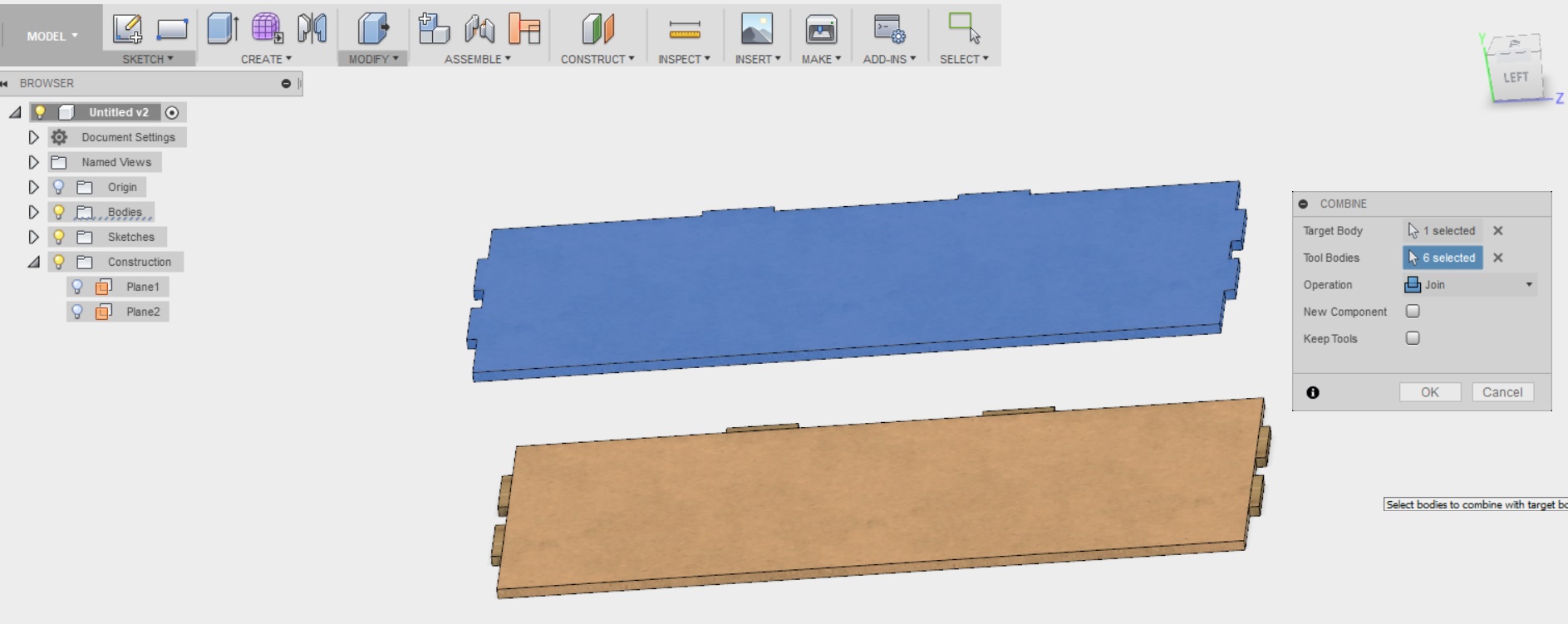
I then repeated these steps for the bottom shelf. This is the result
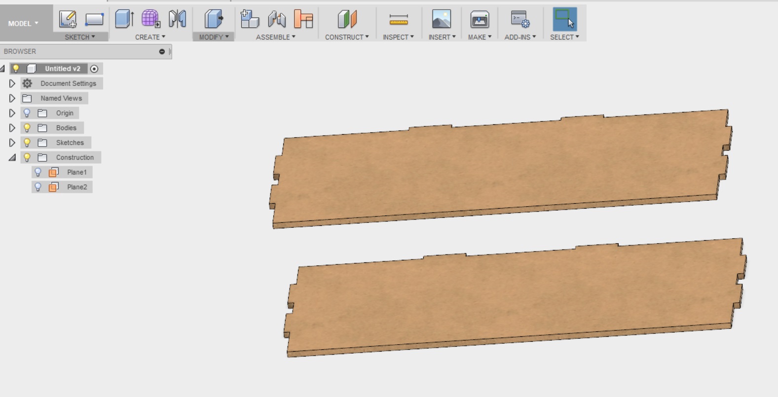
---------------------
Next I created tabs for the back of the bookshelf. I was advised in the tutorial that this is the same process as for the shelves
- I hid other bodies and showed only the back
- I selected Create --> Sketch, and placed it on the front side of the back piece
- I drew three rectangles, created the centerlines for them and made them construction
- I dimensioned the rectangles, leveraging the parameters defined earlier
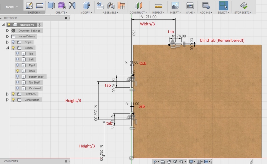
Then created new bodies for the tabs
- I selected Create --> Extrude from the menu above
- I selected the three tabs
- I selected New Body for operation
- I selected the back surface as the depth
- Clicked OK
And mirrored the 3 tabs to the other side
- I chose create --> Mirror from the upper menu
- I selected the three tabs we created
- Chose pattern type to be bodies
- Chose the plane to be the first mirror plane I created
- Clicked OK
And then joined the tabs to the main body
- Selected Modify --> Combine from the top menu
- Selected the back piece as the target
- Selected the 6 tabs for tools
- Unselected keep tools
- Selected "join" for operation
This is the result of that whooooole thing
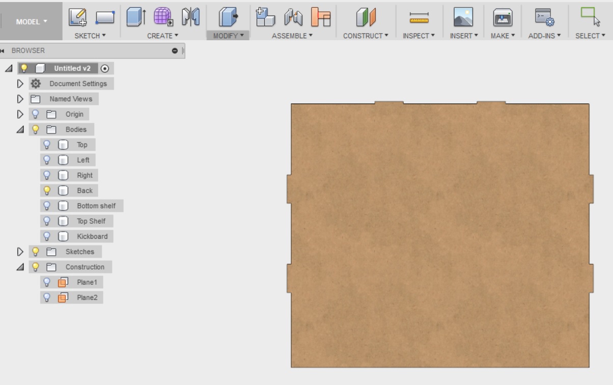
---------------------
Next I created tabs for the sides of the bookshelf. I was advised in the tutorial that this is the same process as for the back and the shelves
- I hid other bodies and showed only the side pieces
- I selected Create --> Sketch, and placed it on the outer side of the left side piece
- I drew two rectangles, created the centerlines for them and made them construction
- I dimensioned the rectangles, leveraging the parameters defined earlier
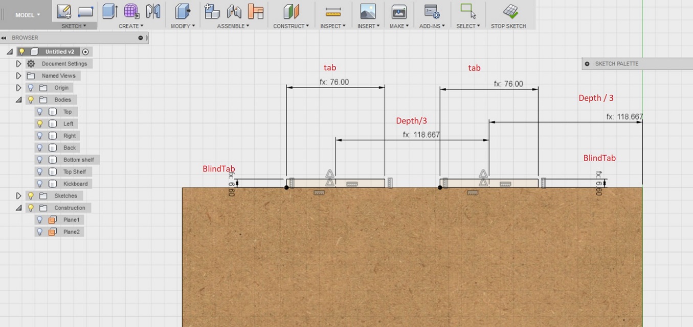
Then created new bodies for the tabs
- I selected Create --> Extrude from the menu above
- I selected the two tabs
- I selected New Body for operation
- I selected the back surface as the depth
- Clicked OK
And mirrored the 2 tabs to the other side piece
- I chose create --> Mirror from the upper menu
- I selected the three tabs we created
- Chose pattern type to be bodies
- Chose the plane to be the first mirror plane I created
- Clicked OK
And then joined the tabs to the main body
- Selected Modify --> Combine from the top menu
- Selected the left side piece as the target
- Selected the 2 tabs for tools
- Unselected keep tools
- Selected "join" for operation
--> Repeat for right side piece
This is the result
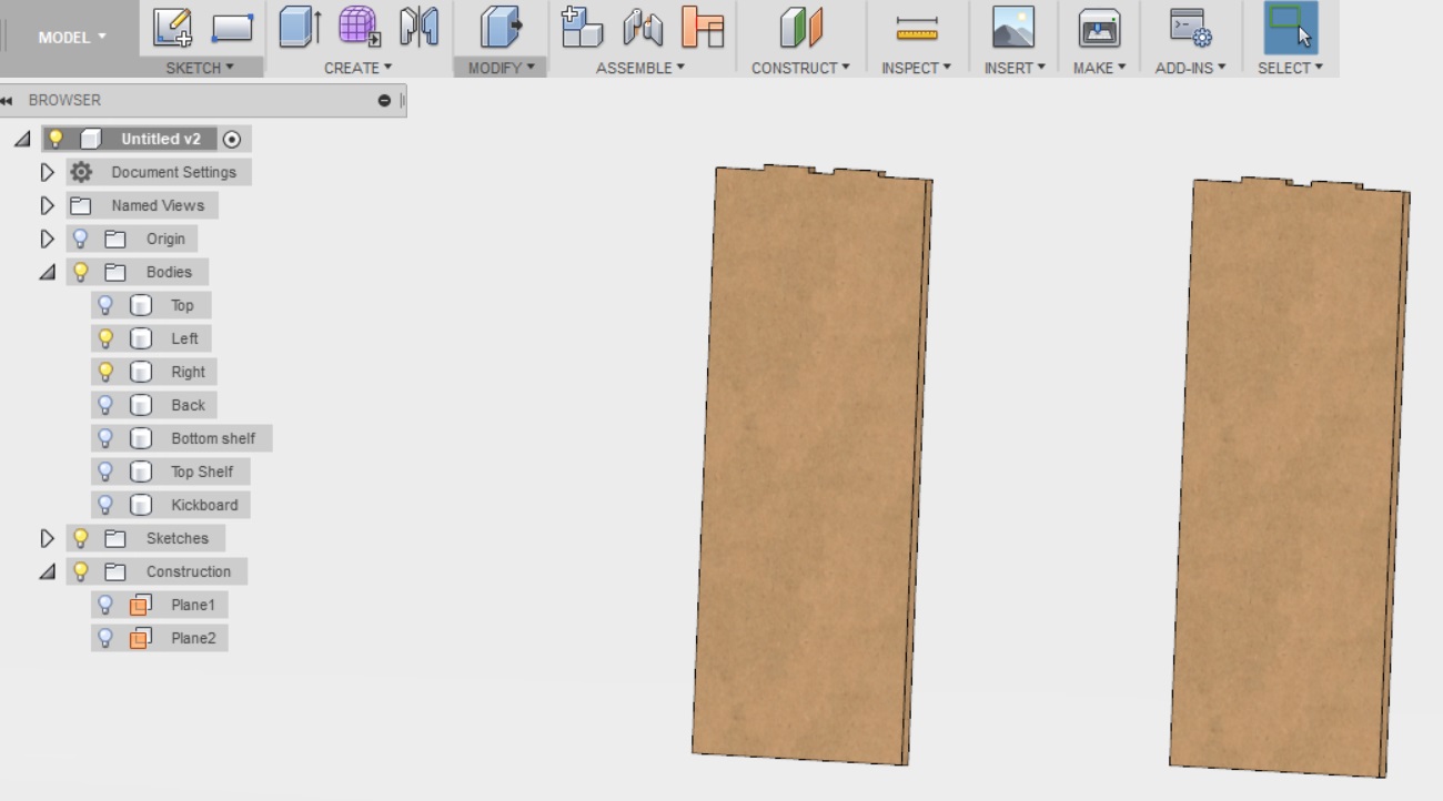
---------------------
Next I was advised to show all bodies, and turn to the back of the shelf. There is a wee problem: The tabs extend into the edge of the top piece as well as the back of the sidepieces. So the sides might fall of and so might the back.
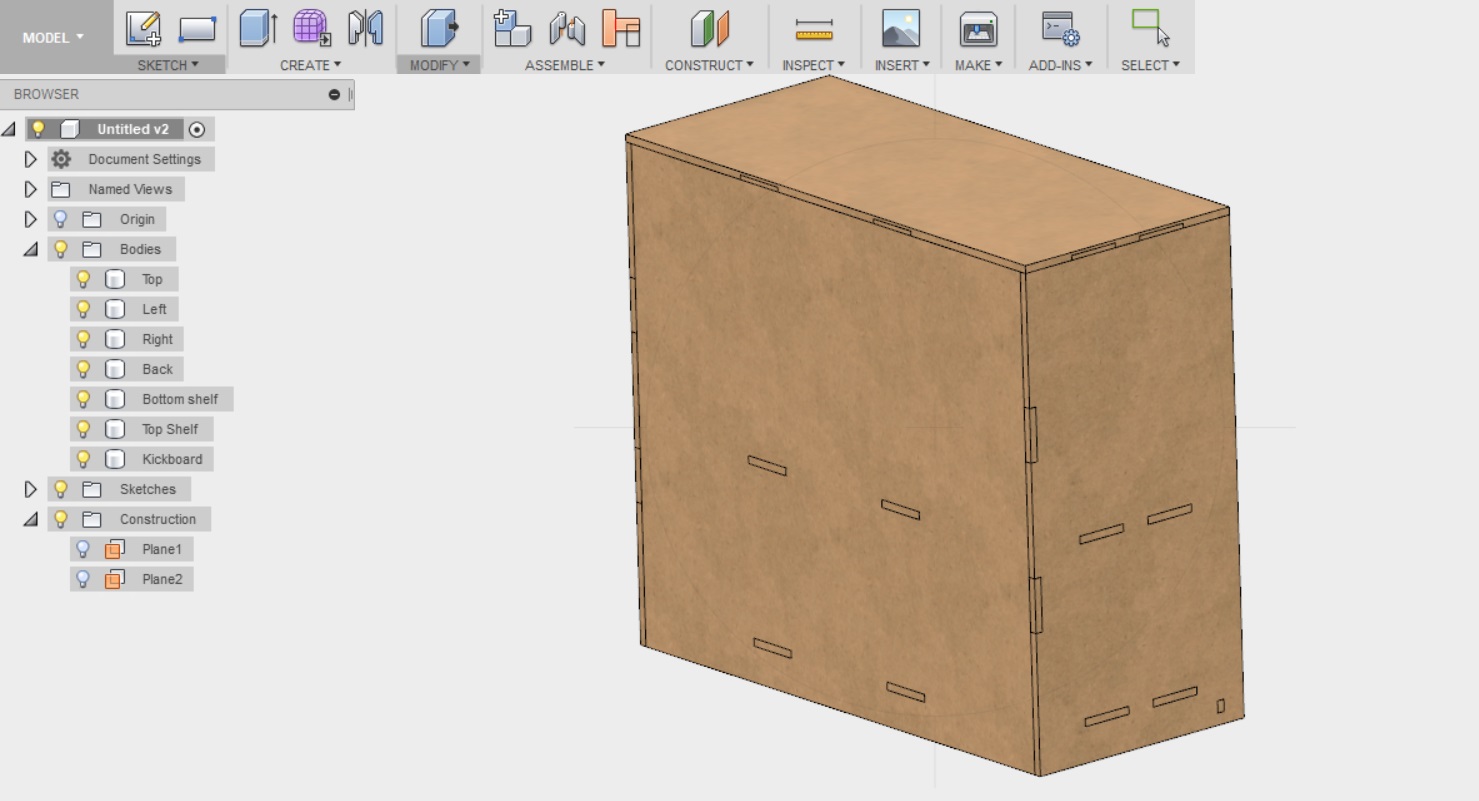
There is a need to add "a lip" as the video calls it
- I selected Modify --> Press pull from the menu above
- Selected the three back faces of the model (both sides and top)
- Selected offset type to be new offset
- Specified the distance to be 13mm
The result
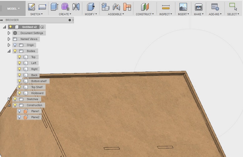
Then I repeated the same for the top piece
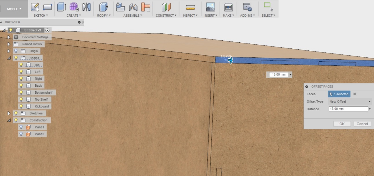
- I selected Modify --> Press pull from the menu above
- Selected the right and left hand sides of the top piece
- Selected offset type to be new offset
- Specified the distance to be 13mm
The result
---------------------
After the tabs are all created, they can be used to automatically cut away pockets. The tutorial again showed me the steps on how to do this.
- First I selected modify --> Combine from the upper menu
- Selected target to be the bottom shelf
- And the tool to be the kick plate
- Operation is set to cut
- Keep tools option is selected
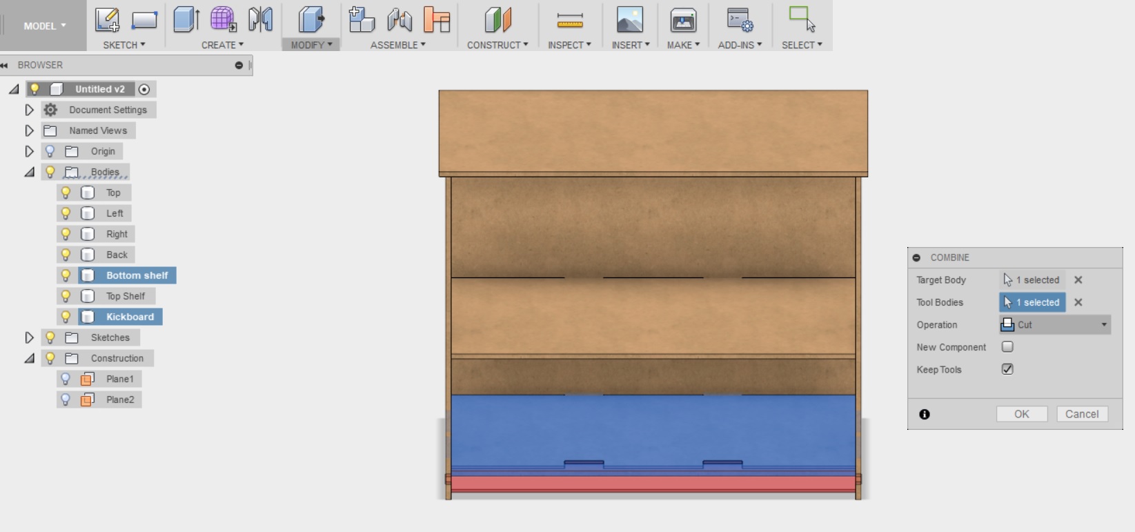
--> When doing the cutting, the target is where you want to remove material from and the tool will do the cutting. If I did not select to “Keep tools”, apparently the software would think that the tool bodies are no longer needed. So it is important to remember to check the box to keep them.
The above process is then repeated with the following combos:
- Target: Back, Tool: Bottom Shelf, Top Shelf
- Target: Left, Tool: Kick Plate, Bottom Shelf, Top Shelf, Back
- Target: Right, Tool: Kick Plate, Bottom Shelf, Top Shelf, Back
- Target: Top, Tool: Left, Right, Back
At this point the model is done! Yay for me!! Now it needs to get prepared for machining, but the bookshelf and all the tabs and pockets are where they are supposed to be.
Files
- Bookshelf design as an editable f3D file
- Bookshelf design as a stl file
Preparing something big
When the model was ready it was time to start preparing it for machining. To do this, I first followed the instructions in the YouTube tutorial
.
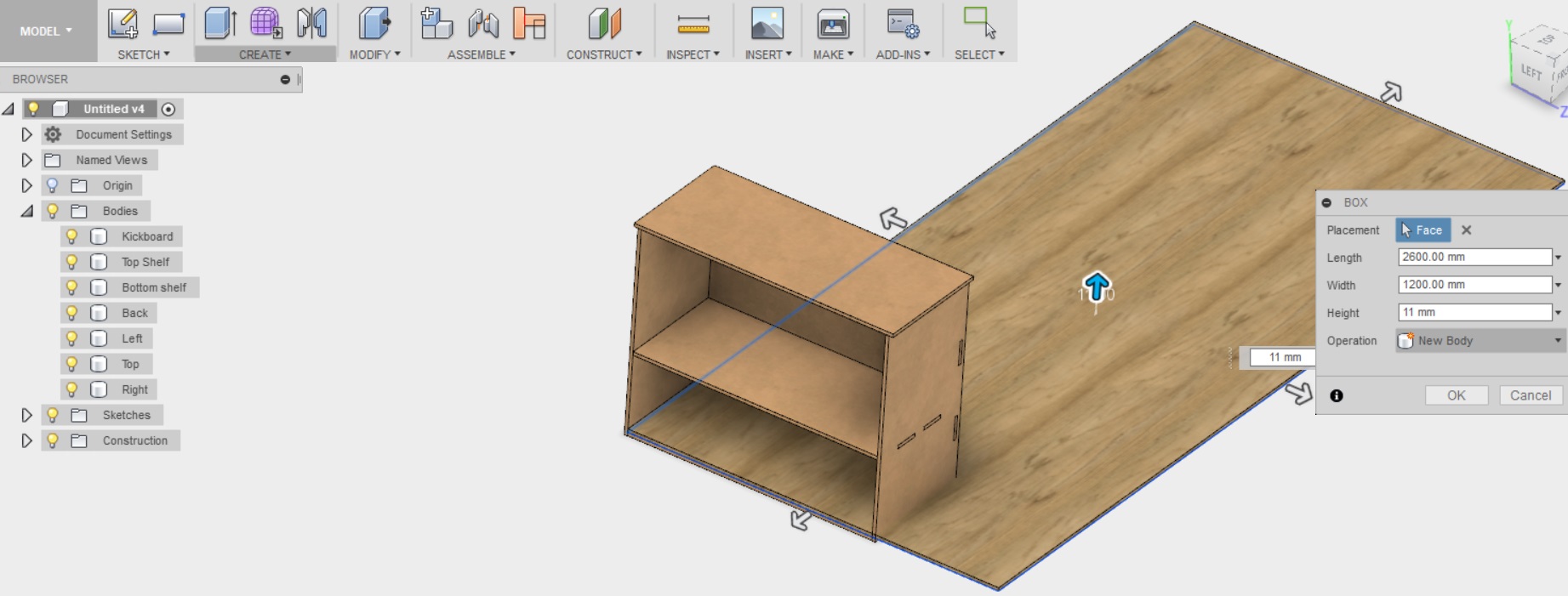
The first thing to do was to create a box that represents the stock that we will be milling the furniture from. We can then use this "stock box" to lay all of the parts flat onto so that we can see how they will fit. The osb board we are using here is 11m thick, it is 1200mm wide, and it is 2600mm tall.
---------------------
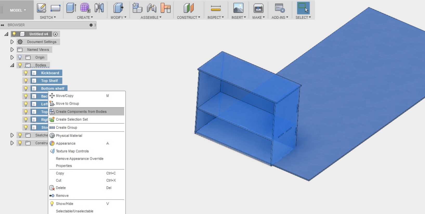
The next thing to do was to turn the bodies in the design into components. The creator of the tutorial explains that he does this as bodies are usually handy when modelling things - When you are ready, you can turn them into components as this format makes operations like combine somewhat easier.
- I selected all of the bodies in the design from the tree in the left
- I right clicked and selected "Create components from bodies"
---------------------
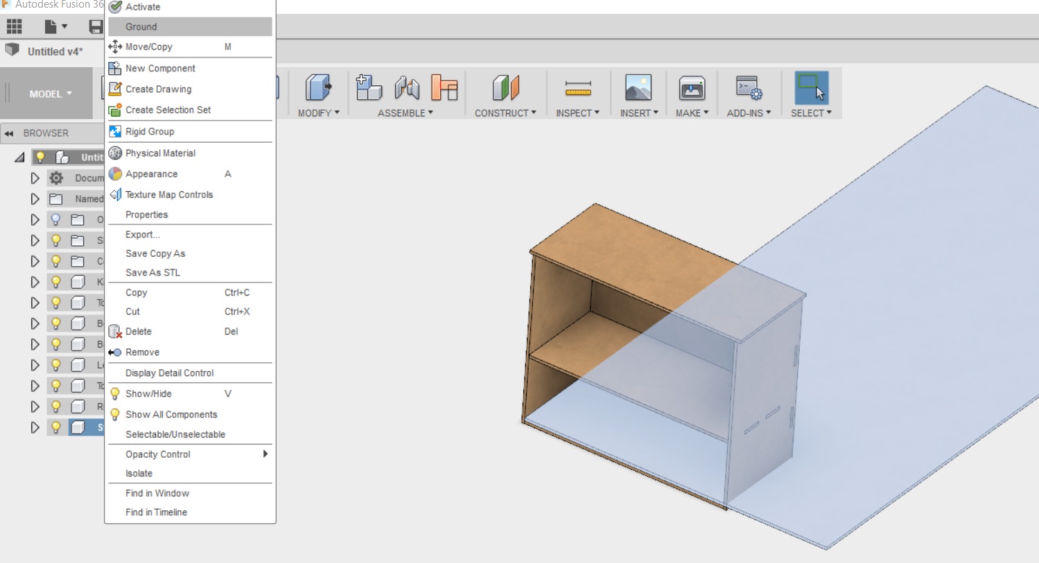
When I had the bodies turned to components, it was time to "ground" the stock component to keep it from moving around.
this was done by selecting the stock component from the tree on the left, right clicking, and selecting ground
---------------------
To lay the parts of the bookshelf flat on the stock, the tutorial advised me to use the assemble --> joint tool from the menu above
- I selected assemble --> Joint
- I selected the bottom face of the top of the bookshelf
- I selected the top face of the stock
- I picked the top face of the stock
- I selected "planar" for the type
- and then I pressed "flip" to get the blind pockets facing up.
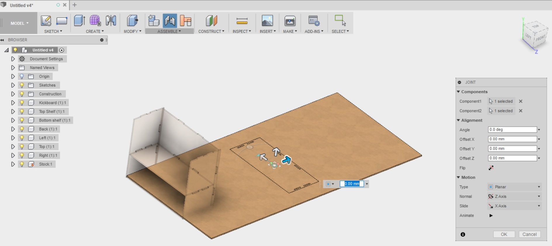
This process was of course repeated for all of the components of the bookshelf. When I was finished all all of them were in the center of the tock board
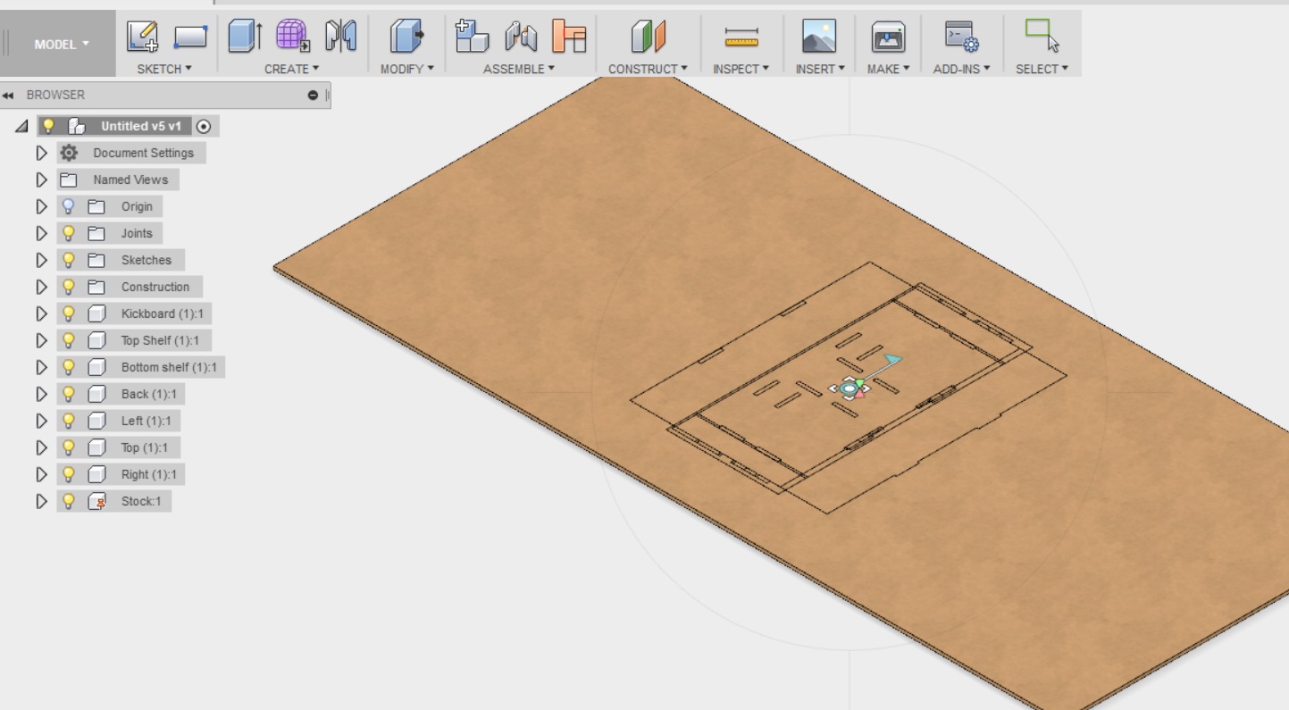
Now I could just move and rotate them to fit the board nicely. It does not really matter how the components are arranged, just as long as e all blind pockets face up, the cnc machine can not cut them otherwise.
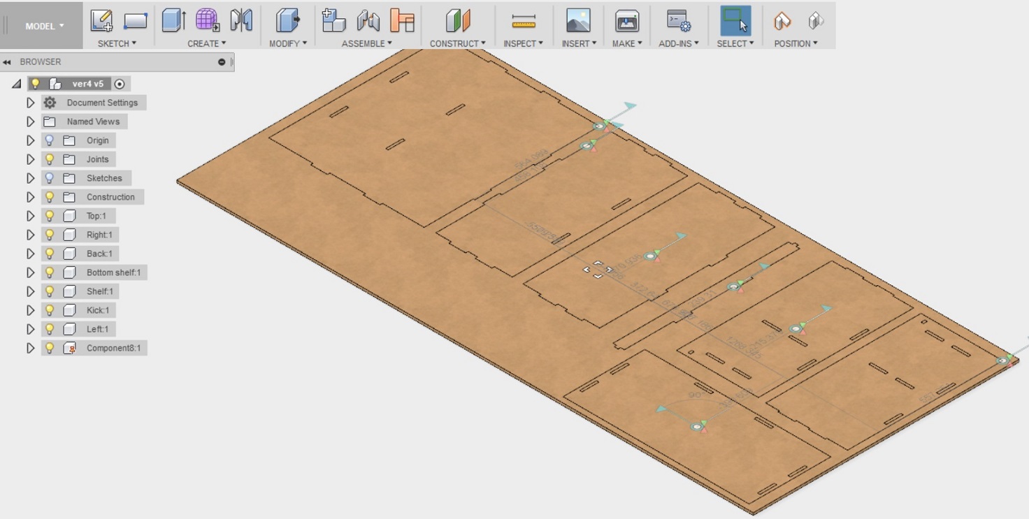
This is the point where I stopped following the tutorial, and started to follow our local instruction on how to prepare the file for the FabLab Oulu CNC machine.
---------------------
Working in CAM
We were advised by out local instructor Eino that before doing anything we need to download two files from FabLab Oulu Wiki page to prepare for the milling:
- The CAM post processor file for Fusion360 (FabLabCNC.cps) that will be used to creating the file for the cnc machine, and
- The file of values for different routing bits (FABLAB ROUTERI TOOLS 2018-2.hsmlib)
After I had done this, I returned to work in Fusion in Eino's supervision
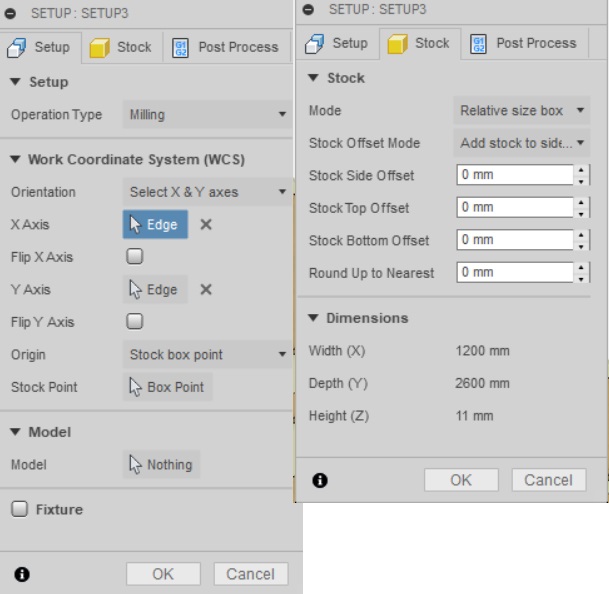
- I switched to CAM mode from the meny above, and clicked Setup --> New Setup from the menu above
- I adjusted the X/Y axis to point the right way and set point of origin to "stock box point" --> the lower left corner of the stock (making sure that it is the corner that is on the top surface).
- In the Stock tab, I changed stock offsets to be 0mm and clicked OK.
---------------------
Next I created 2D pockets for the blind tabs
- I clicked 2D --> 2D pockets from the menu above
- I clicked on "tool" in the first tab, rightclicked on local --> Import tool library. Here we selected the tool file I downloaded from the lab's wiki page. I selected the tool, 8mm flat
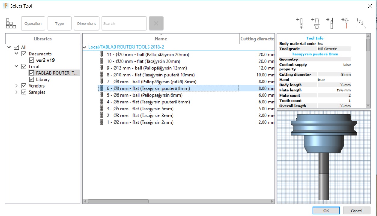
- Next I clicked OK to return to setup window.
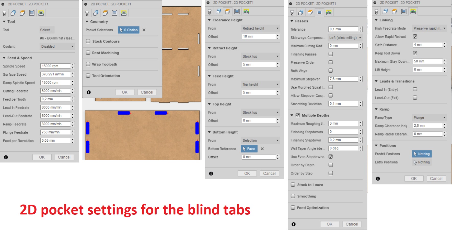
- After selecting the tool, I did not modify any settings in the first tab
- In the "Geometry" tab, I chose the faces I wanted to make the blind pockets in
- In the "Heights" tab, I chose stock top as top height, and the bottom surface of the blind pocket as bottom height.
- In the "Passes" tab, I checked the "multiple depths" - option (meaning that the milling bit will go down multiple times till it reaches the intended depth), input 3mm as maximum step-down (meaning that the milling bit will go down max 3mm at a time to reach the intended depth), and checked "use even stepdown". I also unchecked the box "stock to leave". This is checked only if you want to leave some material there for example for sanding.
- In the "Linking" tab, I unchecked the "Leads & Transitions" boxes (Lead in and lead out). This was done so that the milling bit starts on the exact point defined in the design without any extra cuts. Apparently, as we are cutting wood which is a soft material lead in and lead out are not used, but for hard materials it can be useful (if you can not cut it straight from above - "plunge in", but have to for example have to start from one edge of the stock "lead in") I selected Plunge as Ramp type. Plunge means that the milling bit cuts straight from above. THis is again OK for soft materials like wood.
- When these settings were defined I clicked OK.
---------------------
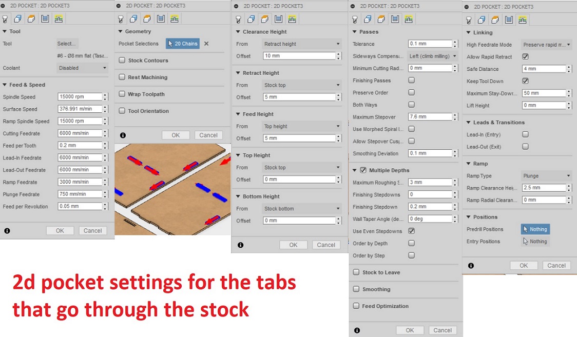
Next I created 2D pockets for the tabs that go through the stock
- I clicked 2D --> 2D pockets from the menu above
- in the "Tool tab", I again selected the 8mm flat tool, and left all other settings as they are
- In the "Geometry" tab, I chose the faces I wanted to make the pockets in
- In the "Heights" tab, I chose stock top as top height, and stock bottom surface as bottom height.
- In the "Passes" tab, I again checked the "multiple depths" - option, input 3mm as maximum step-down, and checked "use even stepdown". I also unchecked the box "stock to leave".
- In the "Linking" tab, I unchecked the "Leads & Transitions" boxes and selected Plunge as Ramp type.
- When these settings were defined I clicked OK.
---------------------
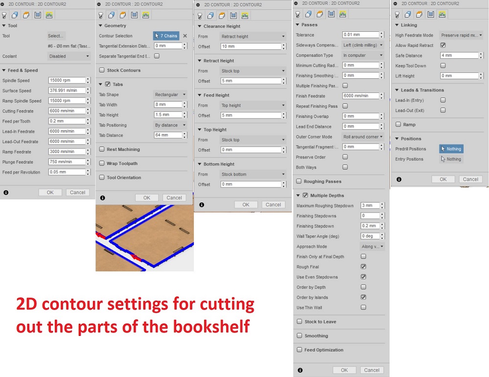
Finally I created 2D contours for cutting the different pieces of the bookshelf out of the stock
- I clicked 2D --> 2D contours from the menu above
- in the "Tool tab", I again selected the 8mm flat tool, and left all other settings as they are
- In the "Geometry" tab, I chose the faces I wanted to cut out (basically the 7 components I had. I also selected "tabs" here, to hold the pieces in place while cutting.
- In the "Heights" tab, I chose stock top as top height, and stock bottom surface as bottom height.
- In the "Passes" tab, I again checked the "multiple depths" - option, input 3mm as maximum step-down, and checked "use even stepdown". I also unchecked the box "stock to leave".
- In the "Linking" tab, I unchecked the "Leads & Transitions" boxes.
- When these settings were defined I clicked OK.
---------------------
Now all my settings were ready for the CNC machine. I wanted to still make sure everything was OK, and ran a simulation of the machining
- I clicked on Actions --> Simulate from the menu above.
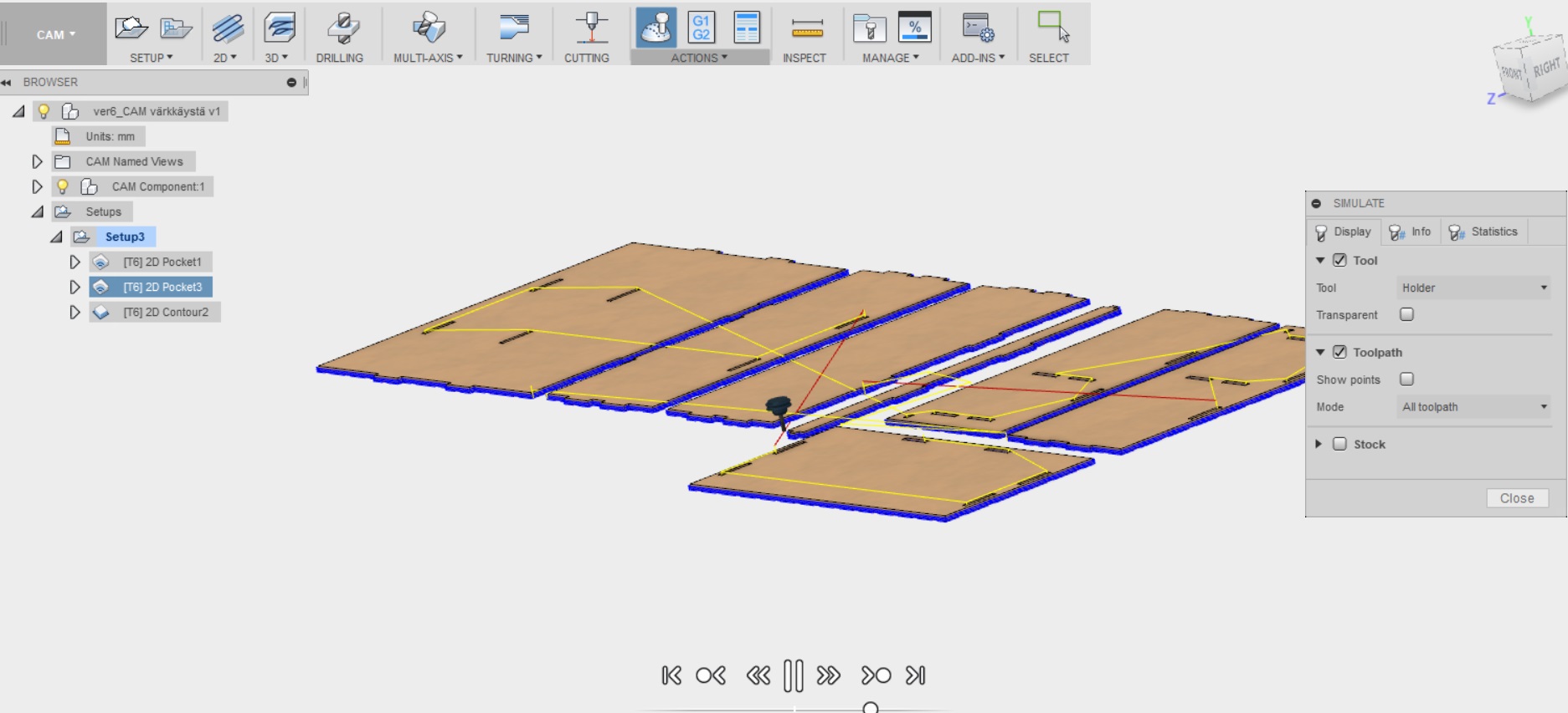
The simulation estimates my bookshelf to be machined in 26 minutes and 42 seconds. It will be interesting to see how true this holds!
---------------------
After the simulation was over, the last thing to do was to convert data of the tool paths as NC code so that CNC machine can understand them. Here I leveraged the post processor file that we saved from the FabLab Oulu Wiki page and saved in my computer in a folder where you can save your personal posts. (C:\Users\hhartika\AppData\Roaming\Autodesk\Fusion 360 CAM\Posts). .
- I clicked on actions --> Post process from the menu above.
- I clicked Setup --> USe personal process
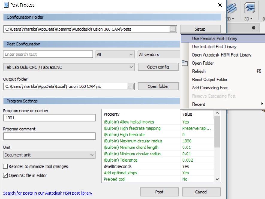
- The FabLabOuluCNC was selected as default as it was the only one on the posts folder
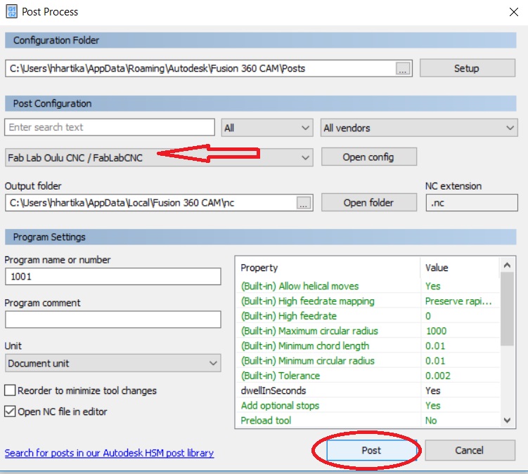
- I clicked "post", and proceeded to save the file on my computer
Making something big
After I was done with defining the processes for cutting, our local instructor Eino doublechecked the file and the settings, just to make sure they were in order and everything should run smoothly. To better prepare myself to work with the big scary machine, I have jotted down the following safety checklist for myself
- Don't mess with the machine when it is working
- Make sure you know where the emergency off is
- Use protective eyewear
- Don't go on your own
I head to the cutting area with Eino to take a look at the machine:
This is the cnc machine at FabLab Oulu. The milling bit goes inside the removable brush. When the machine is working, the brush clears away the debris which is then sucked by the pump.
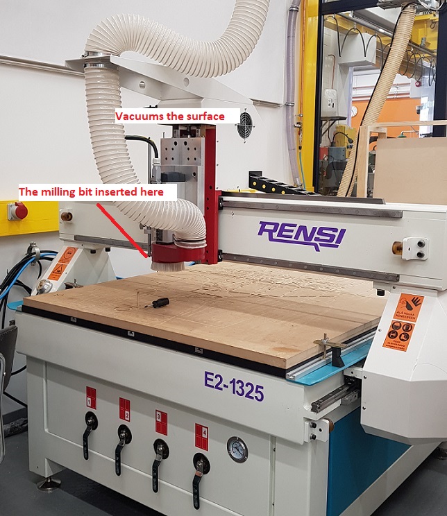
- The first thing I did, was select myself an OSB board that was the size I had prepared my model for. After the selection was done, we lifted it to the milling table.
- We secured the osb board to the table with screws and a screwdriver from areas where we knew there would not be any cutting happening. We did not want them go over my design or be in the way of the tool and break the milling bit.
It was also important to pick screws that do not go too deep into the table
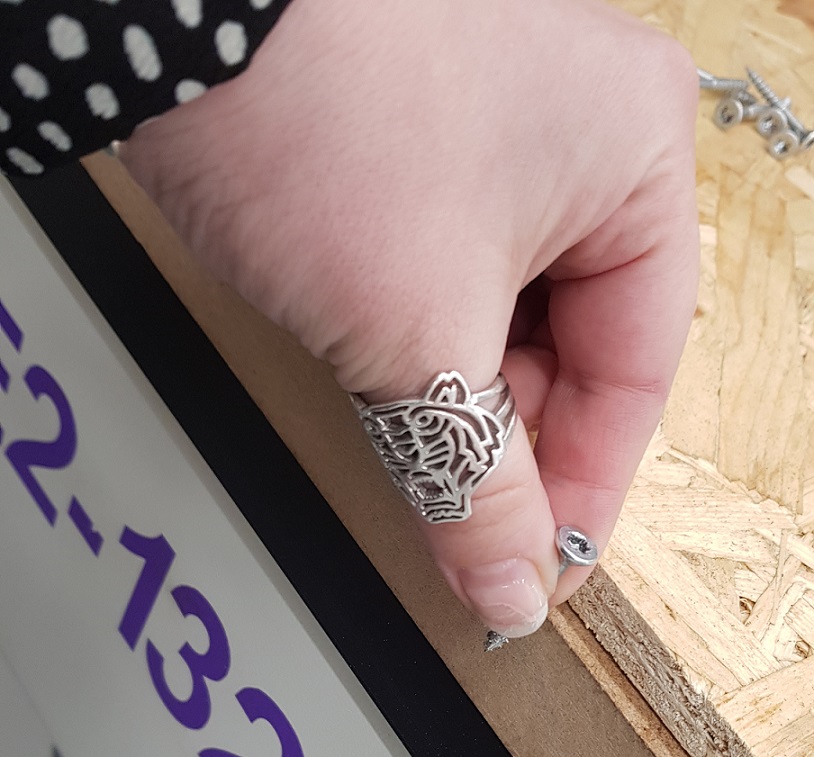
- I inserted the correct milling bit (8mm flat) to the machine, and then it was time to move and start working with the software.
The machine is controlled from a computer next to it.
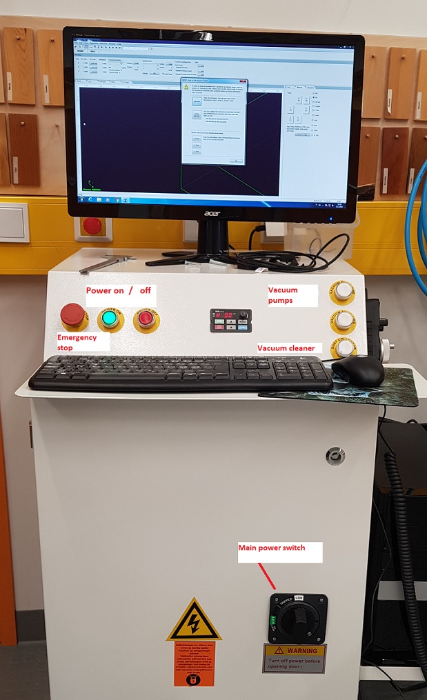
I turned on:
- main power: switch
- machine power: Power on button
- The computer
I opened the NC studio software:
If the machine has been turned off, there is a need to build the mechanical coordinates when the software is started. In this case a pop-up window will appear during startup.
--> Select "all axes", and the program will automatically move all axes to the correct mechanixal origin spot for the X, Y and Z axis. After it is finished, you can just press OK.
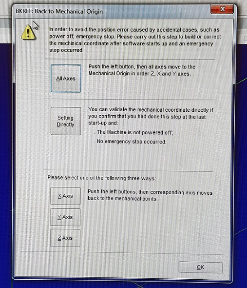
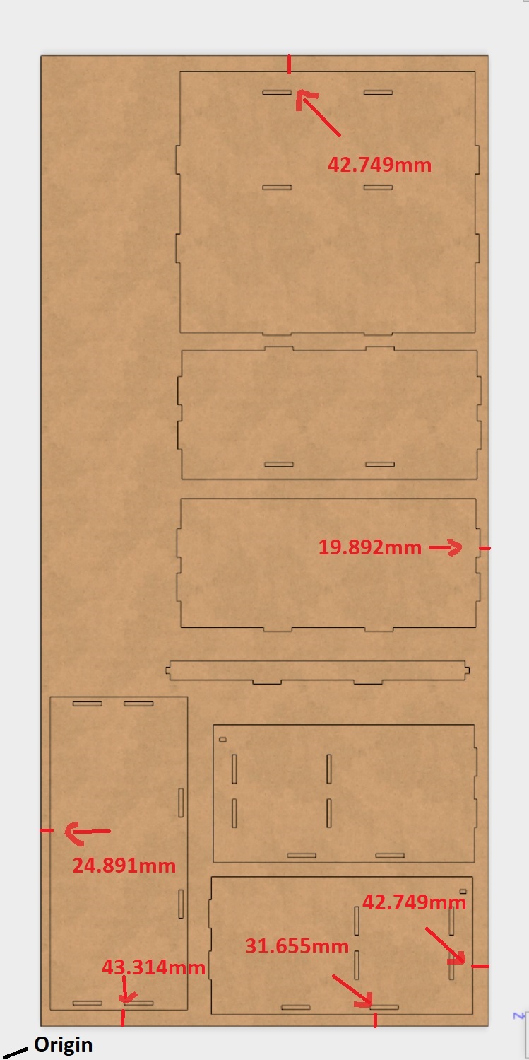
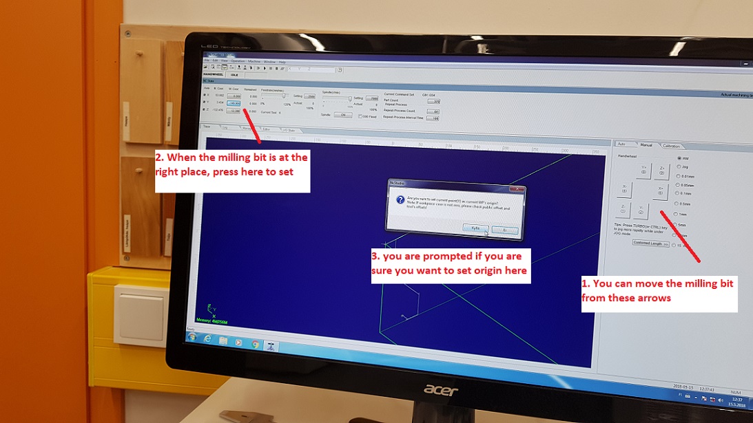
- When this was done, I moved the milling bit to the point in the board where I wanted to set my origin point. The milling bit can either be moved from the arrows on the software, or by handheld controller.I have set the origin of my design to be at the top surface of the stock, in the left "lower corner".
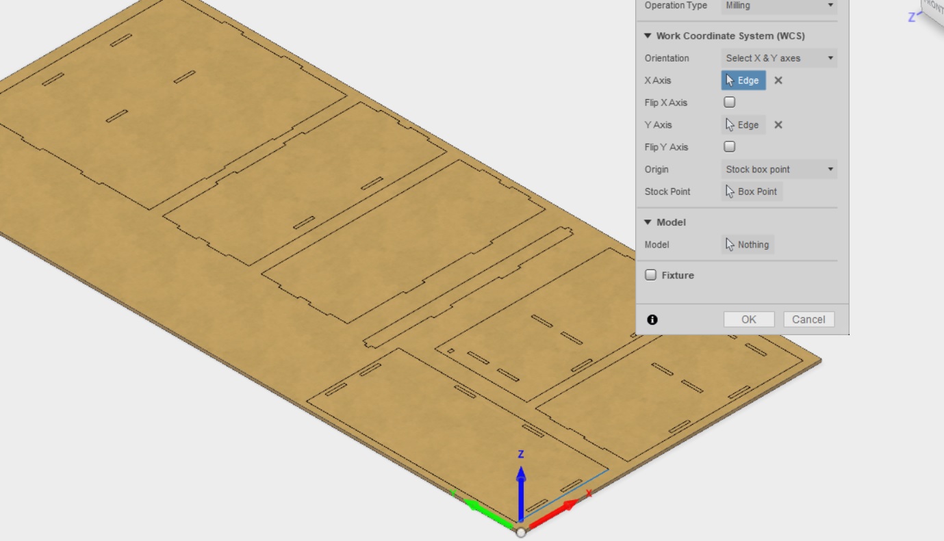
- I proceeded to move the milling bit to the left top corner of the board, and set the x, and Y axus by clicking the X and Y buttons next to the coordinates in the software.
- Next I set the z axis (think depth) by moving the milling bit to the surface of the board, and clicking the button next to the Z axis by clicking button next to the coordinates in the software.
- I removed all the previous movement recorded on the screen (right click --> clear)
- I proceeded to load my NC code to the software (file --> Open and load)
- I ran a simulation before the actual cutting.
--> Here we found an error. I had made my design in a way that it uses the whole board. However, the machine can not move/cut as far back. So it was back to Fusion360 for me. Luckily I had left some room between the pieces to be cut in the model, and I could just move the parts a little closer together, and then run the toolpaths again in CAM, and proceed to generate the NC code again with post process.
Files
- Bookshelf laid flat and CAM done as an editable f3D file (ver2)
- Bookshelf laid flat and CAM done pdf(ver2)
- Bookshelf .NC code (ver2) for the CNC machine
I proceeded to load my new nc code to the software and simulated again, this time all worked without problems.
Note that the button to simulate and to cut are next to each other in the top menu, so hover over them before pressing to see which one is which, to avoid mistakes
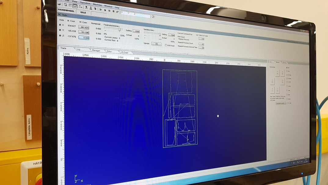
- We allowed left the feedrate to be 120% (5000 mm/min) and spindle speed to be 100% (15000 r/min). These were the default ones. One should be careful with these however, as too much force can cause damage to the machine.
- Next I turned on the vacuum and dust collector
- Clicked cut
When operating the machine
- If feedrate and spindle values were too high, the machine would have made high pitched sounds, so pay attention (remember emergency off!)
- For me, the feedrate and spindle seemed to work, but I think a lot of FabAcademy students had used lower values.
Here the machine is working.
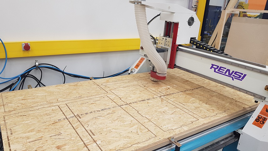
The cutting of the whole bookshelf took about 30 mins. While cutting, the machine left small tabs in to connect the cut piece to the board, so that the process would not be ruined by the piece moving. THey were pretty easy to remove with a carpet cutter. However, on some points it became obvious that the board had not been even in thickness - in the thicker parts there was more material left and removing them took a lot of elbow grease.
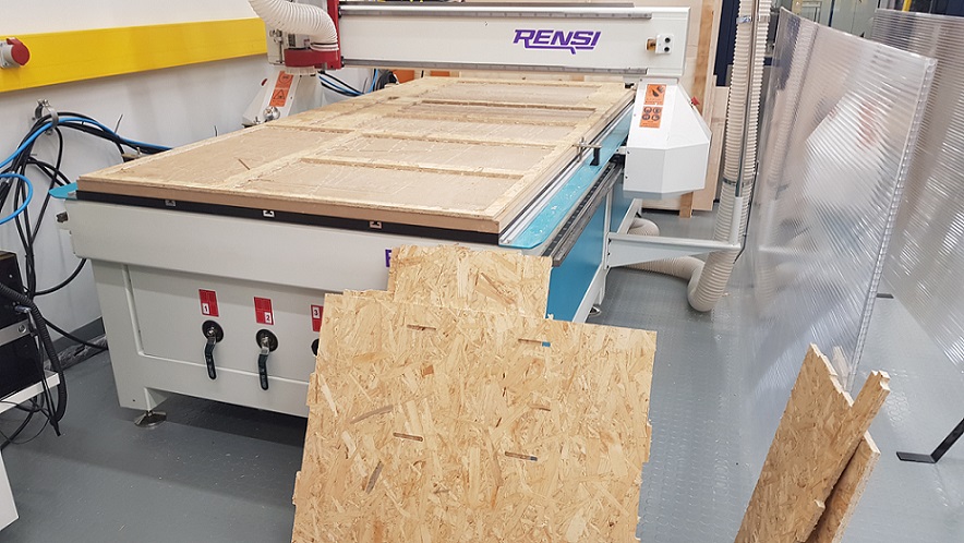
After all parts were ready, I used a sanding belt machine in the FabLab to sand the cut sides smooth. Then I tried to fit the pieces together - Tabs to pockets - but the fit was too snug. I had to use a a file and sanding paper to file a bit off the tabs.
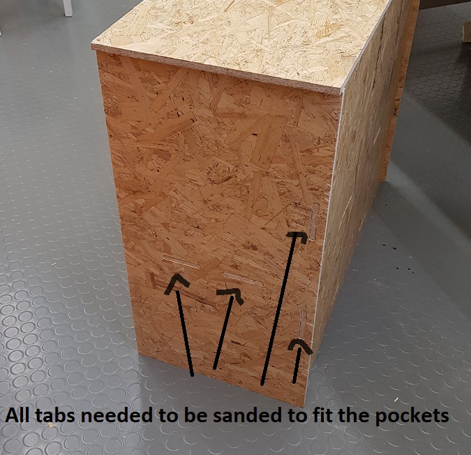
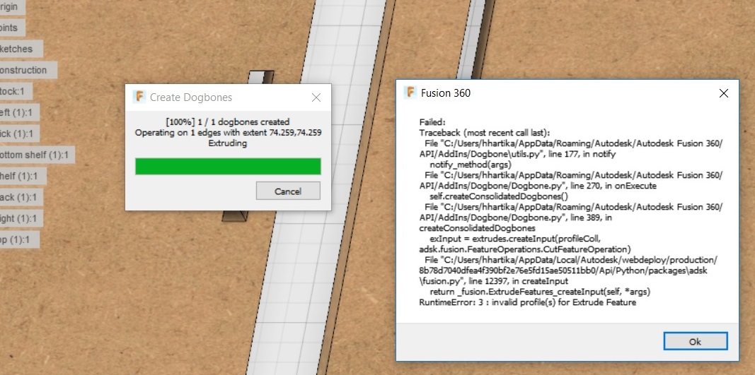
Apparently, this would have been avoided by using the dogbone add-in that I downloaded. I have to say, that I anticipated this, and tried to use it in my project. It did not work though, I kept getting errors whenever I tried to use it, I do not know what went wrong
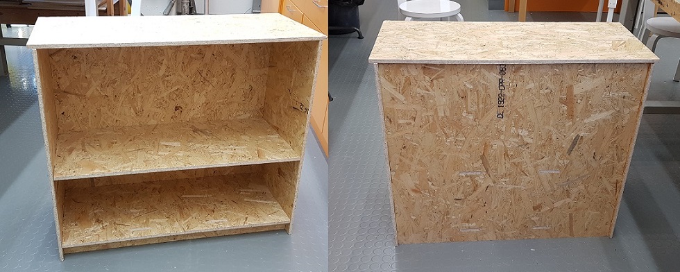
But - the elbow grease did work as well. Here is my finished shelf. Pretty empowering but I am not sure if I will quit my trips to Ikea just yet.
Problems had, lessons learned, questions that remain
- I learned a lot about designing furniture on Fusion, and working in CAM. This was a fun week. What I liked most, was learning about how to make tabs and pockets.
- Lesson learned: When preparing the file for cutting, you should not only take into account the material used, but also the constraints of the machine.
Copyright © Heidi Hartikainen 2018
Template copyright ©Blackrock Digital LLC 2013-2018

This work is licensed under a Creative Commons Attribution-NonCommercial-ShareAlike 4.0 International License.