Week 14: Networking and Communications
This week's tasks:
- Group assignment:
- Sending a message between two projects
- Link to the Group Assignment Page
- Individual assignment:
- Designing and building a wired and/or wireless network connecting at least two processors
Challenges:
- Milling: some parts of the board could not be cut deep enough.
- Programming: I had some challenges in figuring out how to connect everything (c codes, hex files, wires and etc., since this time it was about programming 3 boards and make them connected.
- Only one of the nodes along with the bridge worked properly! I reprogrammed and double checked ecerything but I could not fix the issue.
Considerations:
- Being careful when trying to cut a board that already has some components soldered on it. One could easily break the milling bit, as unfortunately I did.
- Always remember to consider enough space for FTDI header to the edge of the board (Not too much not too less). I have experienced both. I could not do anything about it when it was less but I could manage to cut extra parts when it was too much (but still it was time consuming.)
- For milling it is better to cut the pcb in almost the same size as your board and also to set the z origo in the middle of the board not in the edges.
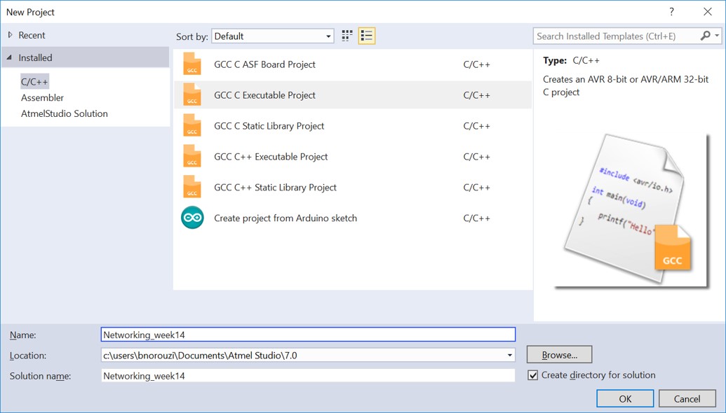
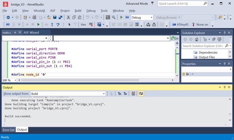
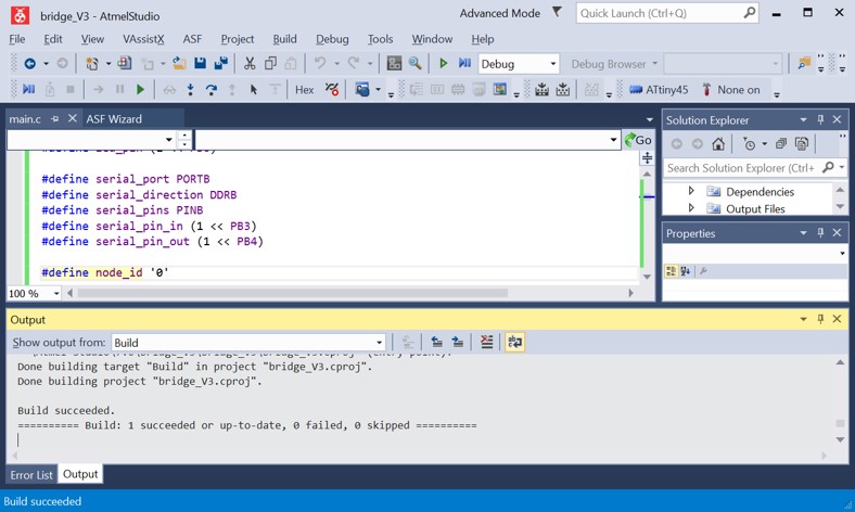
- I created 3 projects for bridge, node1 and node2 using the same code of Neil. What I change was adding #define F_CPU 8000000UL for all codes. And changing the line: #define node_id '0'. For node1 project I changed it to: #define node_id '1' and for node2 project I changed it to #define node_id '2'.
Technology used:
- ATMEL Studio Software
- PuTTy Program
- AVRDUDE
- Eagle Software
- Fabmodules.org
- Milling Machine
- Soldering Iron
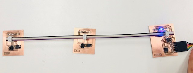
A word about my plan for this week's task
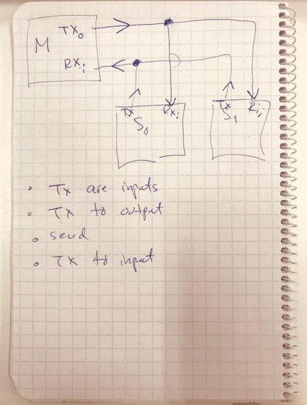
My final project do not have any networking feature so I decide to follow Neil's example for asynchronous serial bus. In this example three ATtiny45 processors are network connected via wire. 2 boards named nodes and one board named bridge, which connects to computer using FTDI cable so it will receive serial input from keyboard and illustrate it on terminal. Through typing 0,1 or 2, a message would be shown containing the node_iD for example node 0, node 1 and node 2. And then the corresponding LED would be turned on. Following Dorina's documentation I also added another LED to the bridge board for indicating power.
Special thanks to Ivan for helping me figuring out the solutions for some problems that I faces in Milling and other stages.
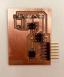
Designing The Bridge Board
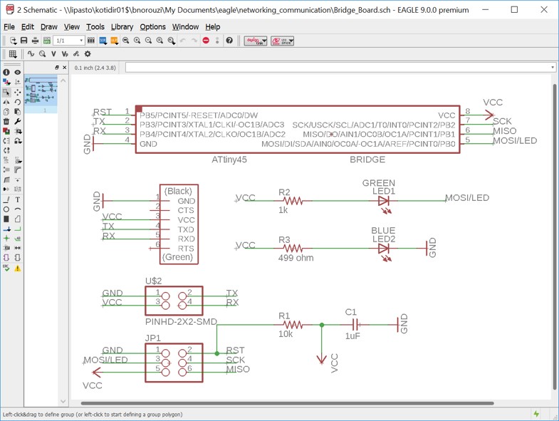
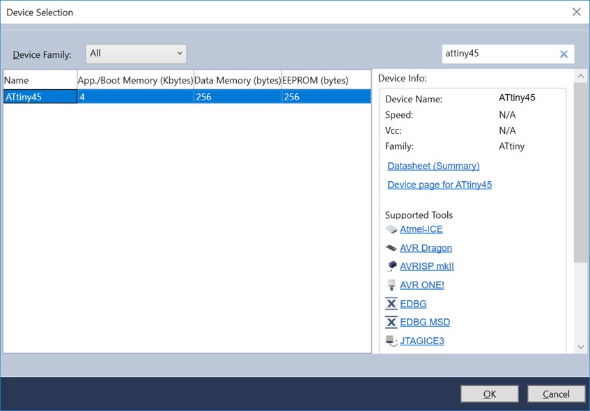
The Microcontroller in bridge board is ATtiny45. I designed the board based on Neil's example (Serial bus > asynchronous)For programming the microcontroller, 2x3 pin header is used.
For connecting the databus (DB) pins RX and TX to the microcontroller and to connect power and GND, 2x2 header is utilized.
FTDI header is used for connecting to FTDI cable and then to PC. The connected pins are VCC, TX, RX and GND.
The Schematic for the Bridge
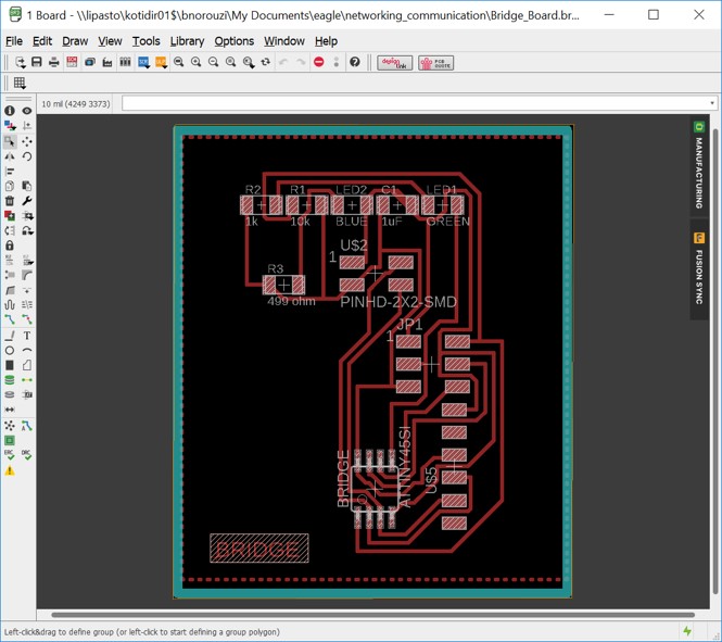
The Board for the Bridge
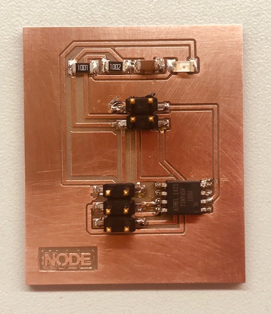
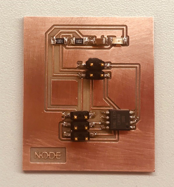
Designing The Node Boards
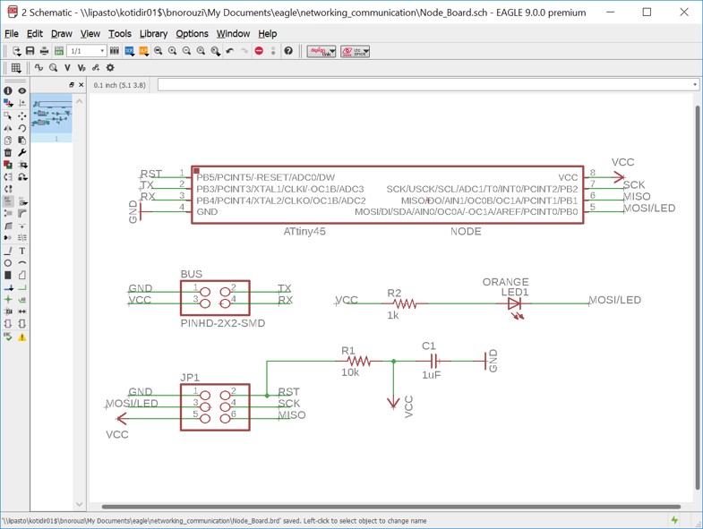
The Microcontroller in node boards are ATtiny45. I designed the board based on Neil's example (Serial bus > asynchronous)
For programming the microcontroller, 2x3 pin header is used.
For connecting the databus (DB) pins RX and TX to the microcontroller and to connect power and GND, 2x2 header is utilized.
The Schematic for the Node
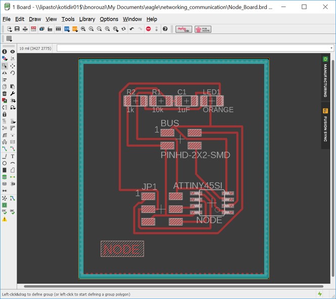
The Board for the Node
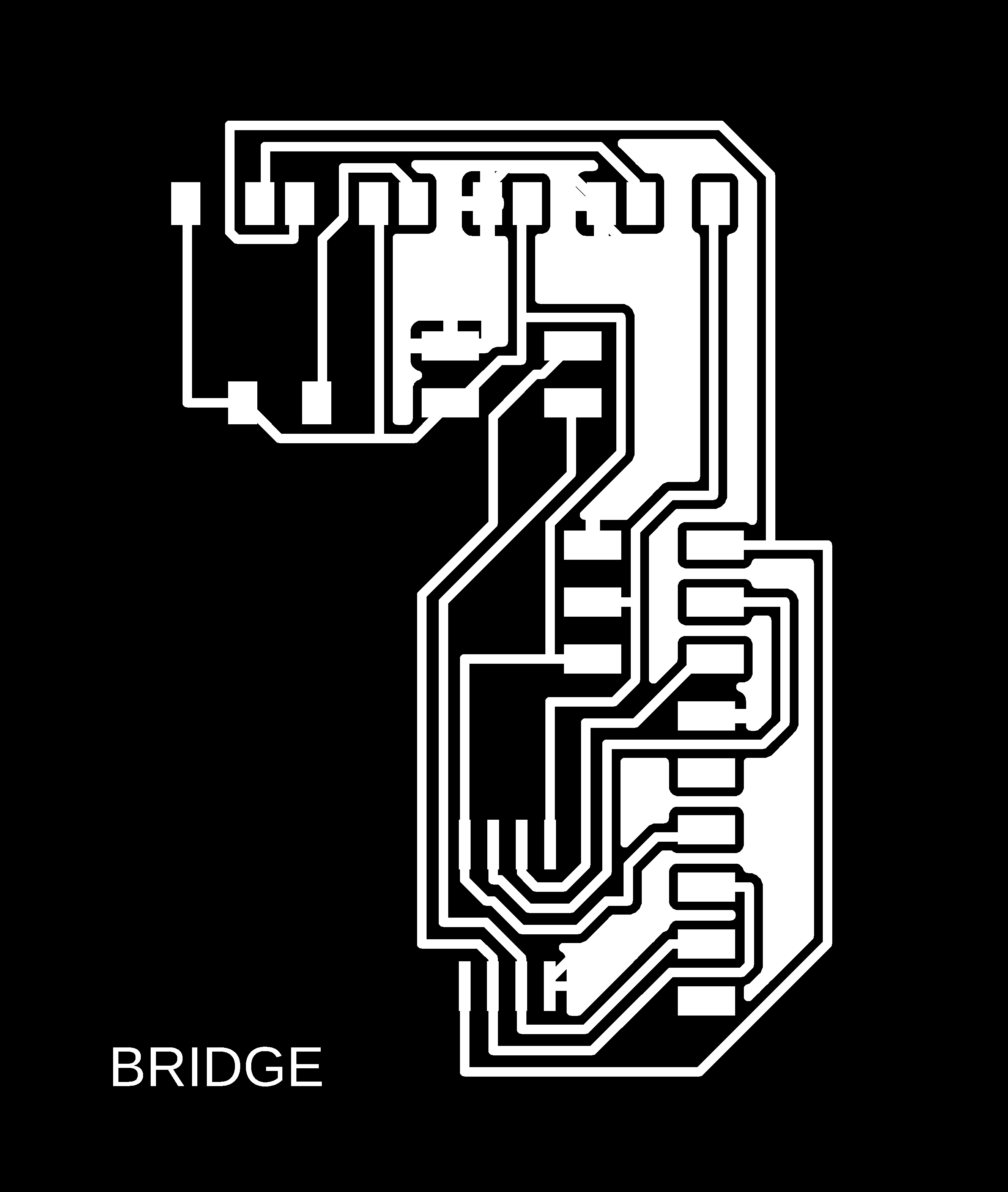
PNG Files for Milling Traces and Outlines
The PNG Files for Bridge Board

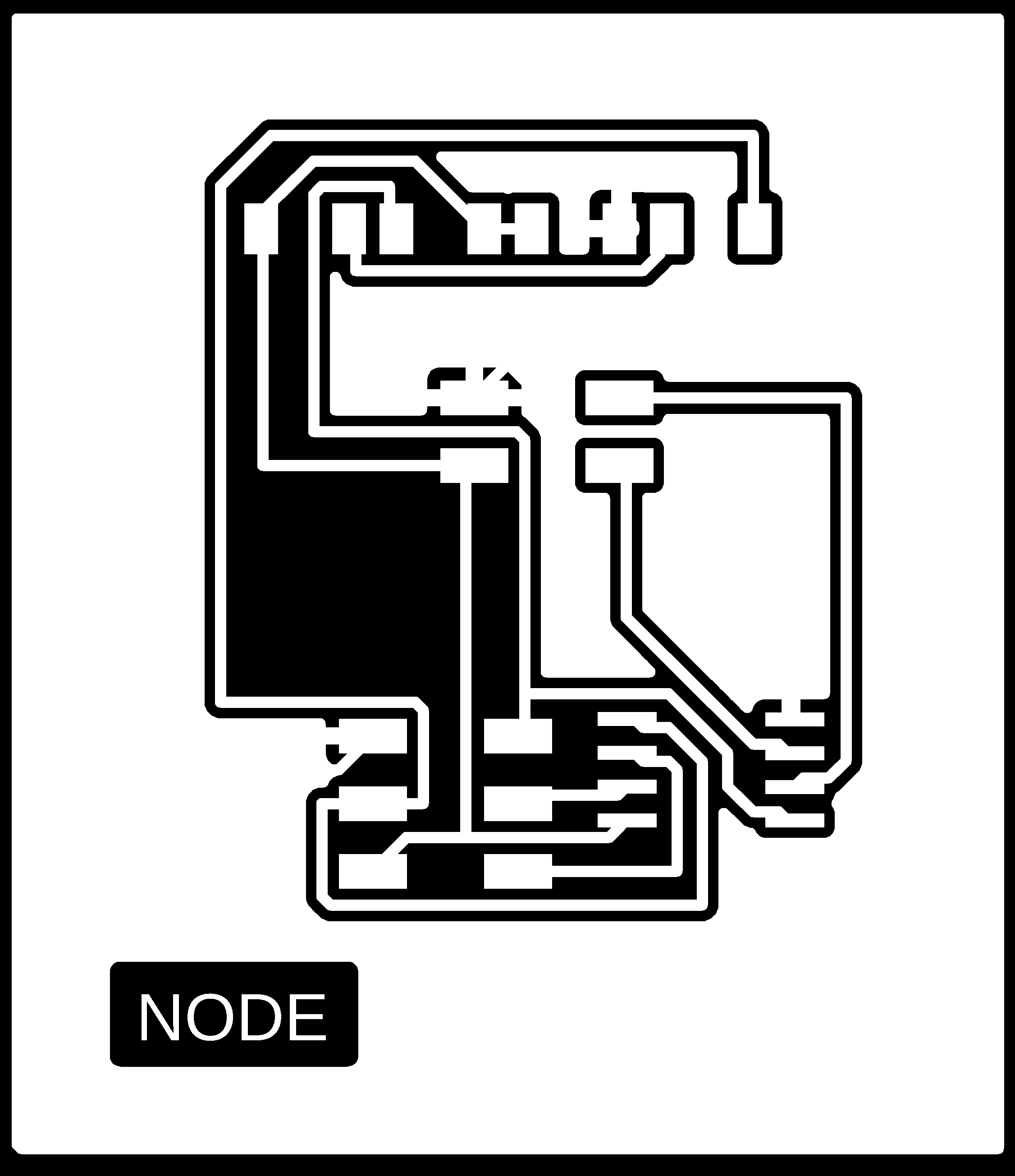
The PNG Files for Node Boards

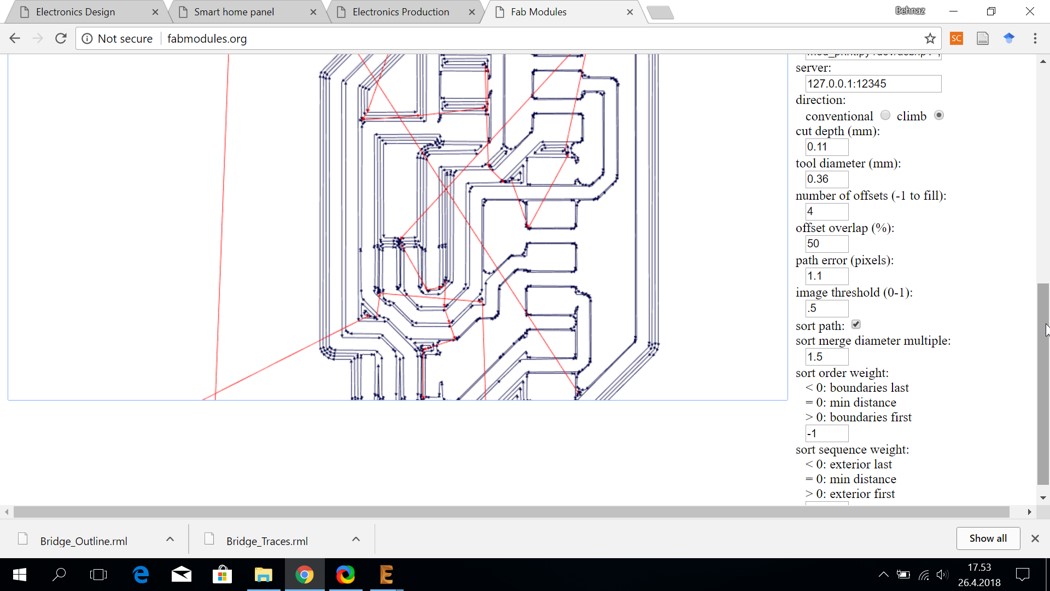
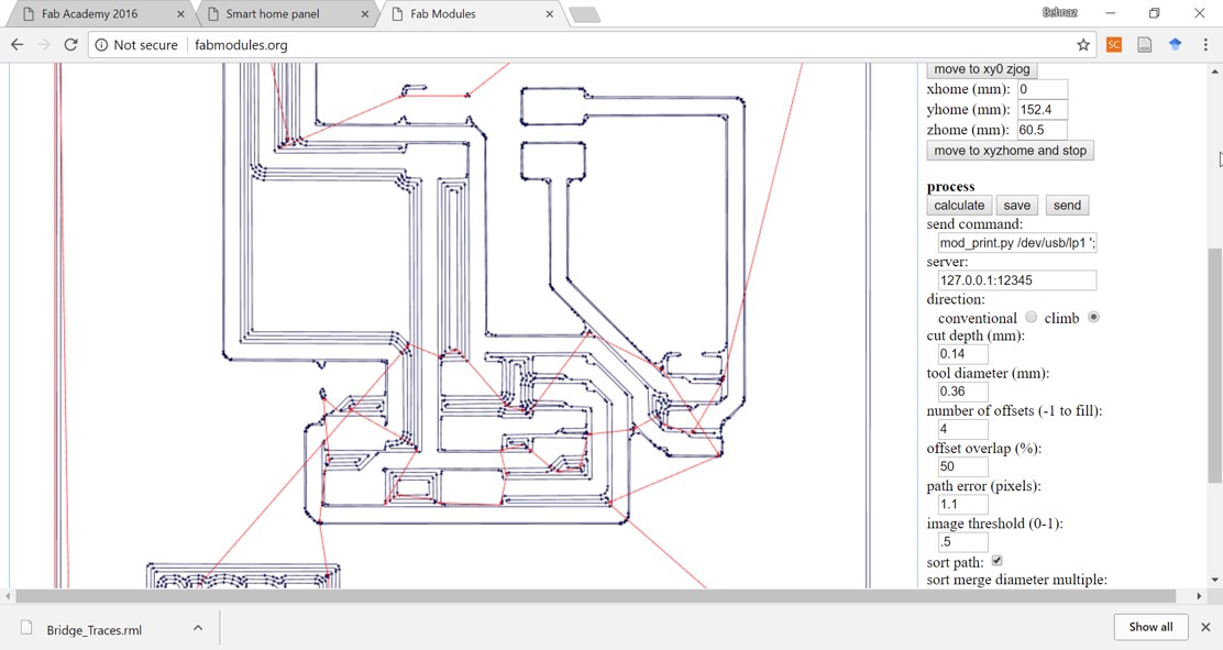
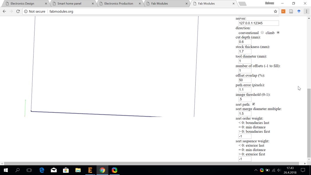
Using http://fabmodules.org/ to Create .rml files for Milling
The PNG Files for Bridge Board
cut depth: 0.11
tool diameter: 0.36
cut depth: 0.14
tool diameter: 0.36
cut depth: 0.6
tool diameter: 1
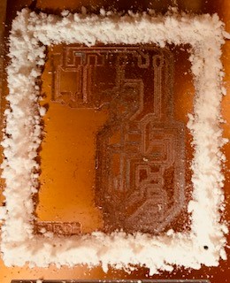
Milling the Boards
Unsuccessful Milling Time
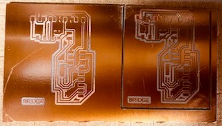
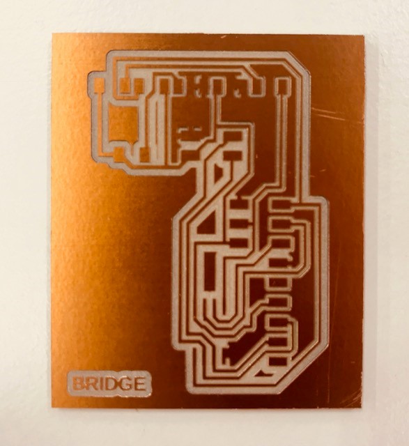
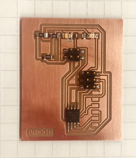
Successful Milled Board for Bridge
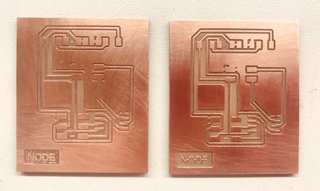
Successful Milled Boards for Nodes
List of Components for Soldering
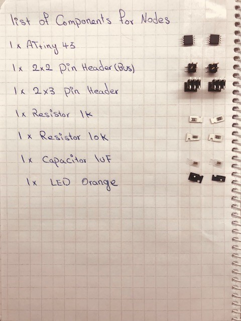
1x 2x2 pin header
1x 2x3 pin header
1x resistor 1 K
1x resistor 10 K
1x capacitor 1 UF
1x LED orange
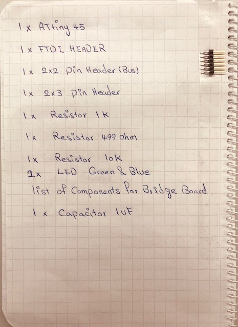
1x FTDI header
1x 2x2 pin header
1x 2x3 pin header
1x resistor 1 K
1x resistor 499 ohm
1x resistor 10 k
1x LED green
1x LED blue
1x capacitor 1 UF
Soldering
Good to mention that I am happy that I am getting more confident and comfortable with soldering. Thanks to Jari for the useful tips that he provided me with, for soldering in a right way.
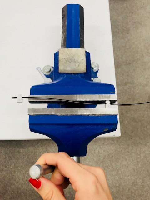
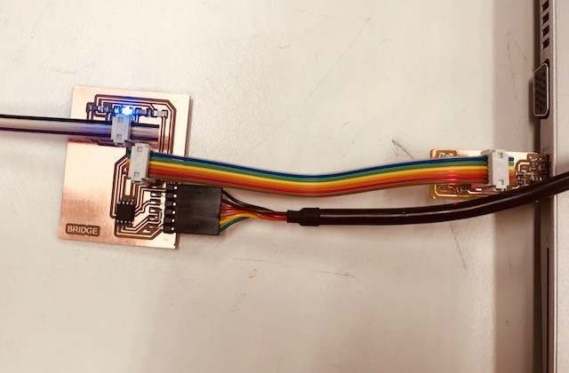
Making the Cables and the Connections
It is important to keep in mind to prepare the databus cable with 4 wires for Rx, Tx, power and Ground.
Programming
- It reads the data from input pin PB3 and stores it in rxbyte (PB3 gets the data/signal directly from TX)
- Then the led flashes
- It checks if node_id ('0', '1', '2' ) was called
- Then it put led on
- Writing on the terminal the node id:
- If yes, DDRB is set/toggled as output direction port and PB4 will be written
- And a variable message is defined for progmem which is written with string "node "
- And the output pin PB4 is written with "node "
- The PB4 is set again as input
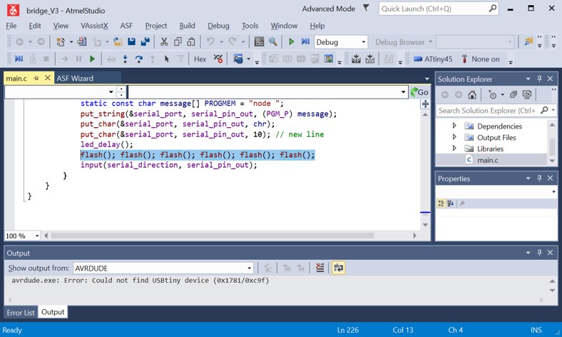
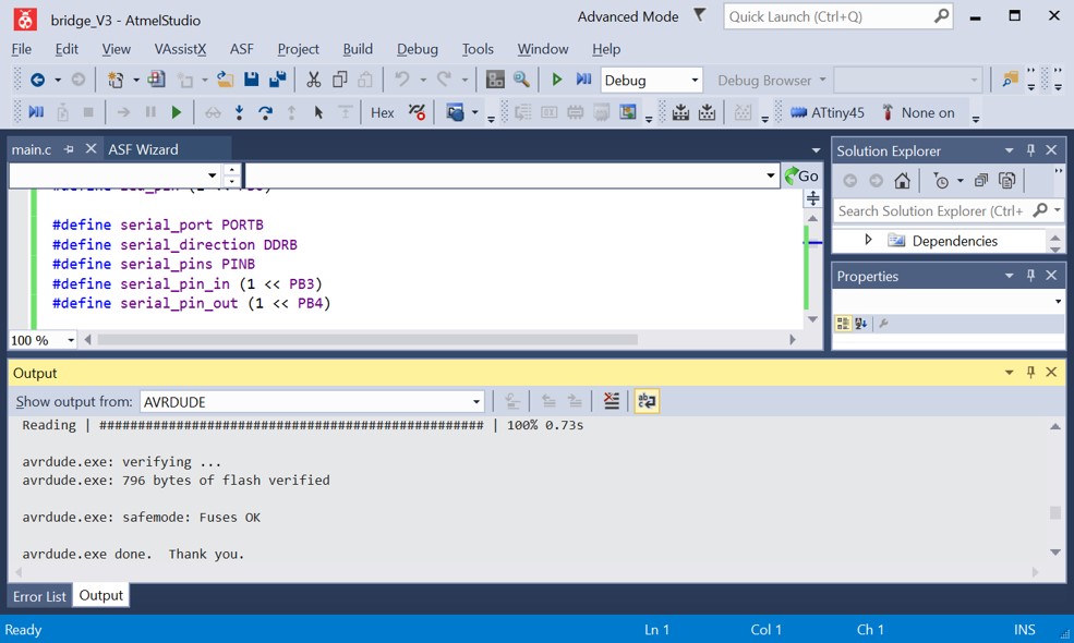
After copying the c code in ATMEL studio and adding the line for defining the clock frequency, I did as following:
It resulted in a hex file. The hex file is written in the flash memory of ATtiny45 microcontroller through AVRDUDE program and the usbtiny programmer.
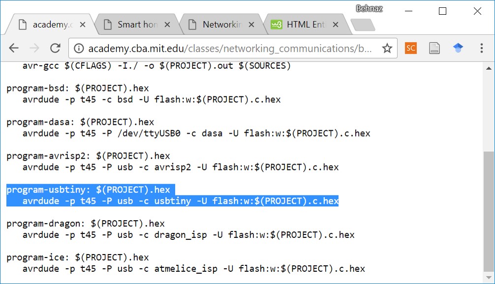
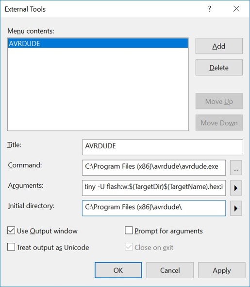
Title: AVRDUDE
Command: C:\Program Files (x86)\avrdude\avrdude.exe
Arguments: -p t45 usb -c usbtiny -U flash:w:$(TargetDir)$(TargetName).hex:i
Initial Directory: C:\Program Files (x86)\avrdude\
And now AVRDUDE is added under the tool tab.
Tools > AVRDUDE
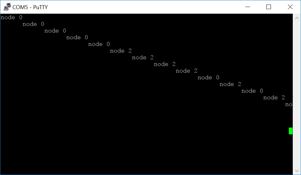
Checking the Results
And opening PuTTy program and inputing the serial line (which COM) and also inputting the value 9600 for speed.
Original Design Files
Schematic for BridgeBoard for Bridge
Schematic for Node
Board for Node
Board for cutting extra part of Bridge
Bridge Traces .rml file
Bridge Outline, .rml file
Node Traces, .rml file
Node Outline, .rml file
bridge c code
node 1 c code
node 2 c code
bridge hex file
node 1 hex file
node 2 hex file