- Assignment 14
Mechanical Design
This week we worked in a group to build the mechanical part of a machine. As there are many of us in the team, we have designed two machines that will interact with each other: a handball and a basket-robot. Together with Alberto, I worked on the basket-robot.
Structure
The basket-robot is designed to escape from the balls that are shot at him. It is equipped with
omnidirectional wheels so that it can move easily in all directions without having to rotate on itself.
Alberto was mainly responsible for the design and construction of the wheels, instead I concentrated
on the body where are placed, the motors, the control electronics and the basket equipped
with an IR sensor to detect the presence of the ball.
Design
To make the body I chose a 4mm multilayer poplar laser cut, this material is strong enough to support the
4 motors (about 1kg in total).
With Solidworks I designed the various parts and assembled them virtually to make sure that the various
joints matched.
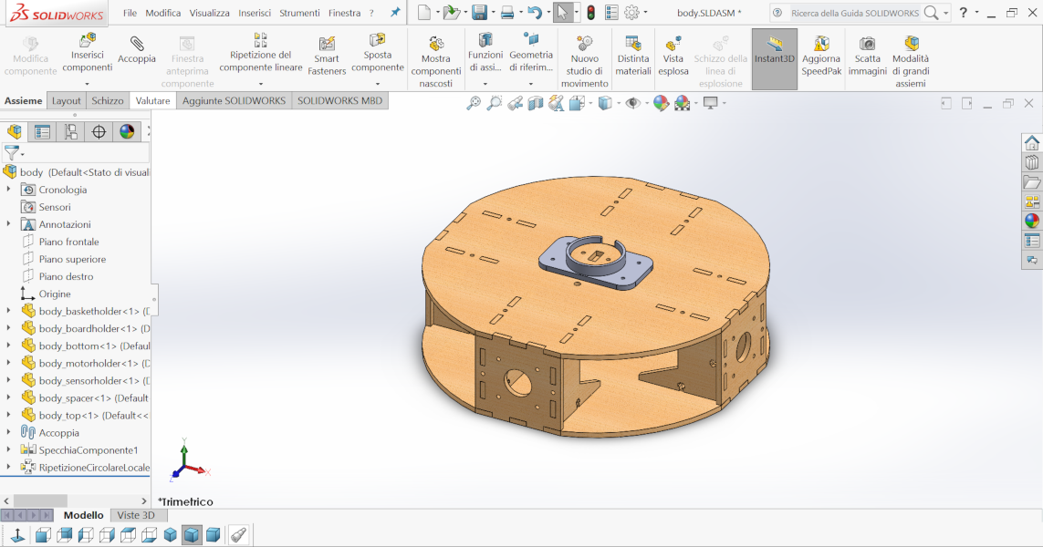
Figure 1. Assembly
To keep the parts perpendicular to each other together, I chose to use 10mm countersunk screws, so I drew a sort of cross to house the nut.
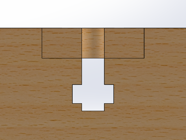
Figure 2. T-Slot
In total there are 4 different drawings for the structure plus one for the support of the IR sensor and one to hold the board. In advance I also designed three rectangular holes in the lower base to house the electronics later.
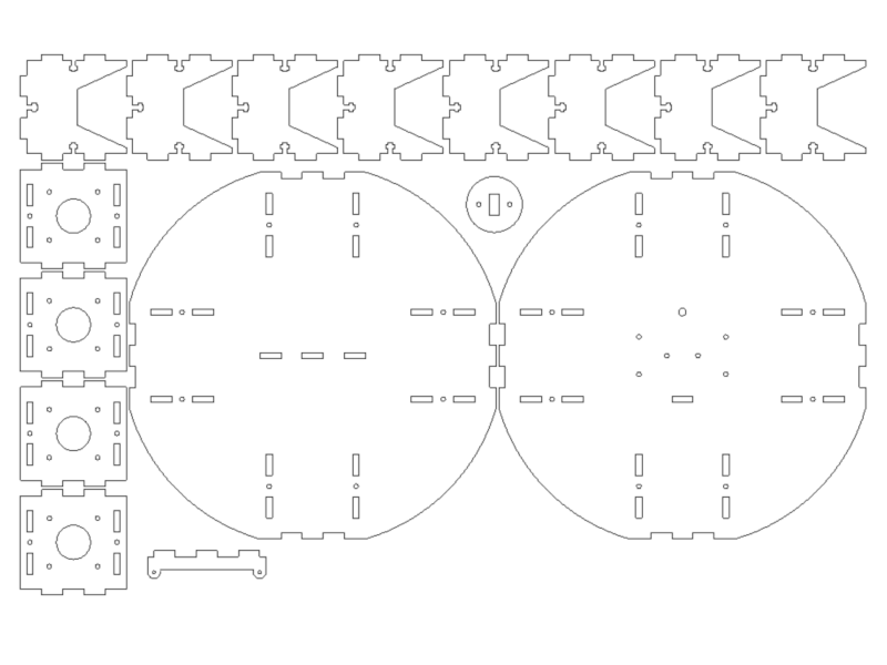
Figure 3. Layout for laser cut
In addition to these parts to be lasered I have also designed a support for the basket. Since the basket will
be the most fragile part of the machine and you have to try more shapes to ensure that the ball does not
bounce off I decided to print it separately. This guarantees me a faster basket change as it will only be
snap-in.
I left the design of the shape to
Catherine.
download basket-holder 76.2 KB (.stl)
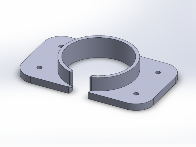
Figure 4. Basket support
Assembly
Before proceeding with the assembly I had to countersink all the holes for the screws so as to position the head flush with the surface. I started assembling the motor holder with the two side crossbars and then I mounted them on the bottom base. For each side I used 4 M3x10 screws with relative nuts.Then I inserted the motors with 4 M3x8 nuts each and finally I fitted the omnidirectional wheels.To do the motion tests I left the upper part open and I started to mount it separately by first putting the IR sensor with two M3x16 screws with self-locking nut and after the support for the basket using M3x8 screws threaded from below and started directly into the plastic previously threaded.
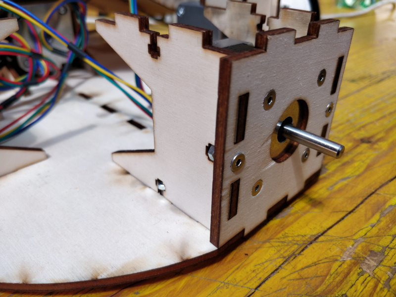
Figure 5. Assembly of bottom part
Group Assignment
More info on the Opendot machine design page.