- Assignment 10
Input Devices
Among the various inputs shown in the lesson I chose the touch and I made a slider that controls a led.
Test
Before trying with ATtiny I did some tests with Arduino UNO and some surfaces made from aluminium tape.
Hardware
Following the Capacitive Sensing Library guide I chose two 3.3M resistors and connected them between the sending pin (4) and the receiving pins (2 and 6) repeatedly. I also connected the receiving pins to the two sensors.
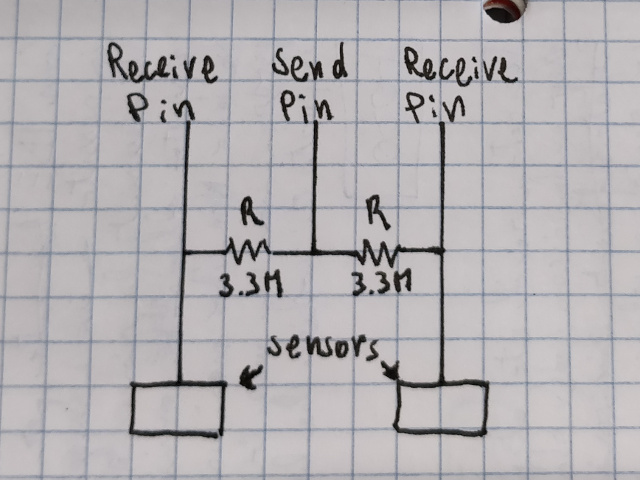
Figure 1. The schematic for two capacitive sensors
To make the sensors I did some tests gluing pieces of aluminum tape to cardboard. Those geometries worked well from right to left, but also from top to bottom, which I would like to avoid.
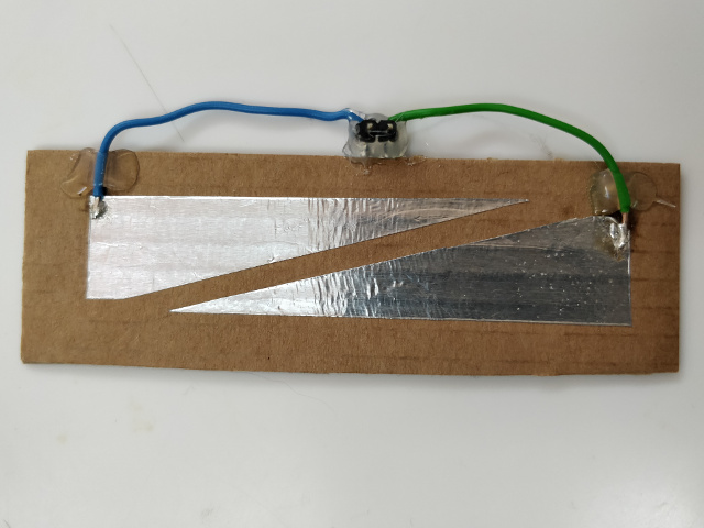
Figure 2. First test with aluminium tape on cardboard
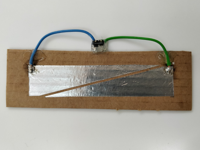
Figure 3. Second test with aluminium tape on cardboard
Then on a piece of MDF I improved the geometry to avoid this unwanted effect.
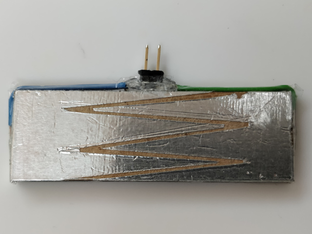
Figure 4. Last test with aluminium tape on MDF
Software
On Arduino IDE I wrote a small program that reads the
values from the sensors and remaps them from 0 to 1000, after that using the difference of the two readings
and a minimum threshold will understand if I am sliding to the right or to the left. I printed all this
information on the Serial Monitor for debugging.
For the development of the code I was based on the library
CapacitiveSensor
of Arduino and his Demo Sketch.
Result
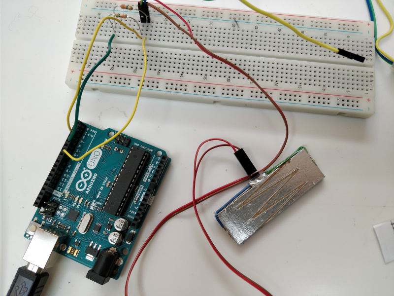
Figure 6. Arduino UNO and breadboard
Custom board
After ensuring that the firmware worked properly I wrote a porting for a custom board made by me.
Hardware
On EAGLE I designed an all-in-one board containing an ATtiny45, the sensors and a led. To draw the sensors I used the Polygon feature.
download TouchSlider 30,2 KB (.zip)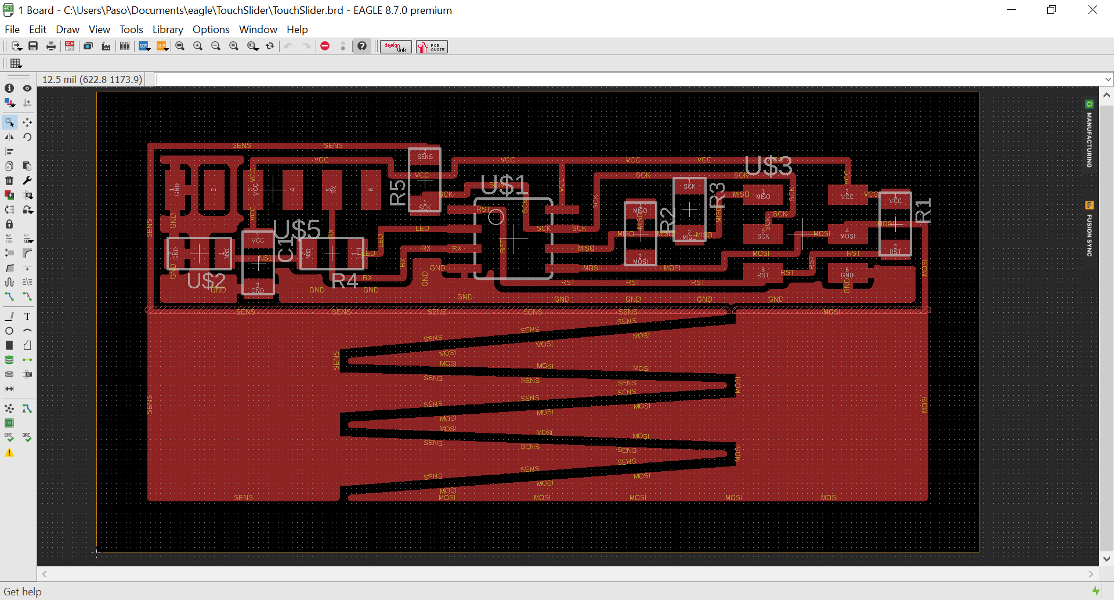
Figure 7. The board EAGLE view
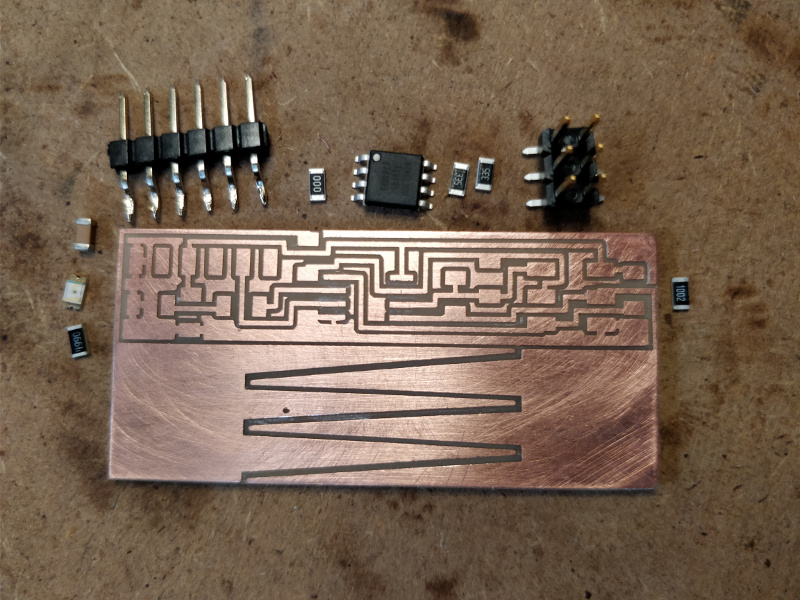
Figure 8. The board with components
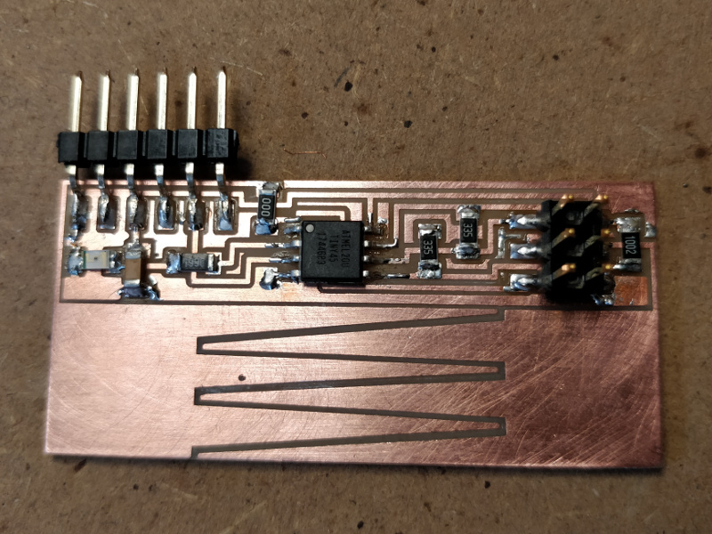
Figure 9. The board assembled
Software
At first compilation for ATtiny45 I found the sketch too big, so I had to optimize it by deleting unnecessary variables and using Port Manipulation.
// analogWrite(LED, led_value * 51);
OCR1B = led_value * 51;
Fix
After several attempts I realized that the pin I had chosen for the PWM was not normally usable so I had to swap two pins (if I had done it before I would have also simplified the routing). This wasn't enough, however, and I also had to add a line in the code that enables the timer for that PWM.
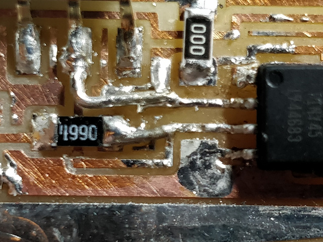
Figure 10. The fix
/* set pin 3 of PORTB for output*/
DDRB |= 0b00010000;

// Enable PWM mode; OC1B set at $00, cleared on
// match, /OC1B disabled
GTCCR = 0x60;
Result
That is the end result after a tin plating of the sensor pads. I would also have liked to test with SoftwareSerial but unfortunately the little memory available from the microcontroller did not allow me to do so.
download TouchSliderFirmware 6,67 KB (.zip)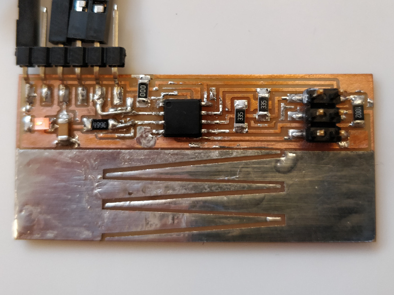
Figure 11. The board finished and tested
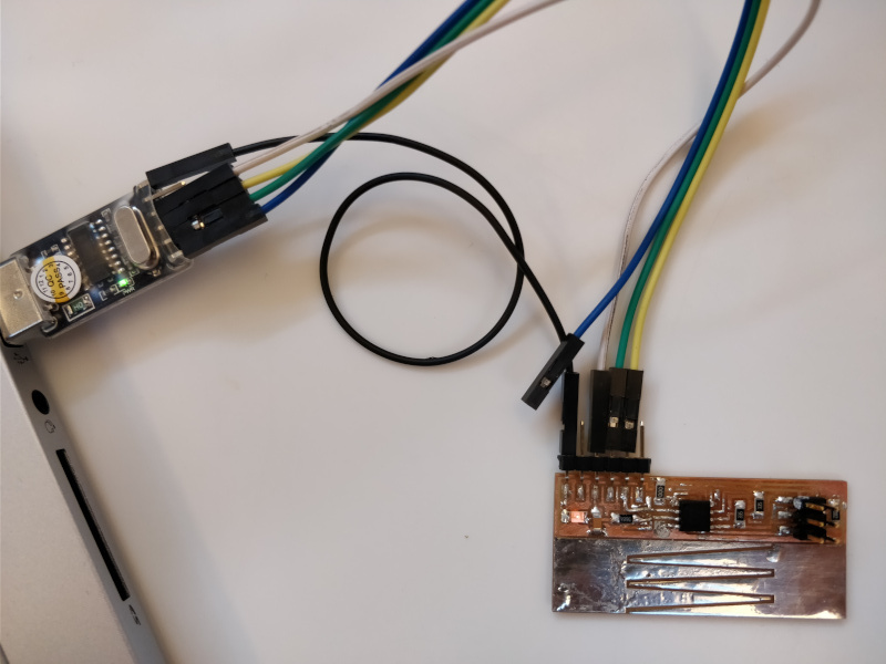
Figure 12. The connection with my PC
Group Assignment
More info on the Opendot group assignment page.