Week 12
Output Devices
Group assignment
Individual assignment
Learning outcomes:
- Demonstrate workflows used in circuit board design and fabrication.
- Implement and interpret programming protocols.
Have you:
- Described your design and fabrication process using words/images/screenshots.
- Explained the programming process/es you used and how the microcontroller Datasheet helped you.
- Explained problems and how you fixed them.
- Included original design files and code.
Individual assignment:
1. Introduction to the output:
For this weeks assignment I will use a vibration motor, also known as shaftless or pancake vibrator motors, as an output. The goal is to receive the input signals of the sensors that I used in the previous week, the input one and send a vibration whenever it is stablished that the subject is not in a correct position. If the accelerometer sensor detects that my back doesn't have a good inclination angle it will vibrate to warn me.
I will use this motor as an output. The data sheet can be found in this link. The main characteristics of this motor are:
- Vibrating motor at 3V
- Operating range: 2-3.6V
- Starting voltage: 2.0V : this means that we have to apply at least this voltage to be sure that is going to start. However is recommended to switch it hard on and off at a voltage above the guaranteed start voltage.
- Rated current: max 60mA
- Rated speed: 13000±3000rpm/min
- Direct current resistance: 33/65 ± 20% Ω
- Measuring conditions: Temperature [25±2℃], Humidity [45~85%]
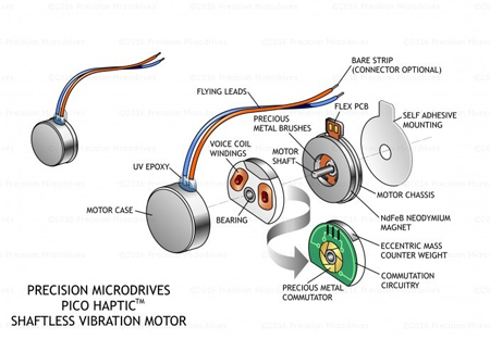
We can see the parts of the motor in the next image. For more information about the parts you can go to this site.
2. Designing the PCB:
In order to design the circuit for the motor I followed the advice of this tutorial which tells you the basic knowledge that you need to create the motors circuit.
As said in the Output lecture, output signals from digital microchips and microprocessor ports are designed to drive no more than 5~15mA. Since all vibration motors consume more current than this, a driver circuit is required to control the flow of power to these motors. The most common method to do this is by using a MOSFET.
Circuit components:
In the page that I linked before there is a diagram with how the circuit can be constructed depending on the use of a P or N MOSFET:

-
Mosfet: we can find two types:
- P MOSFETS: they work well down to 1.5V supply voltages. The drive signal is active-low. High-side.
- N MOSFETS: work better from 2v or higher because they tend to have a higher Vgs gate turn on-voltage. N-channel MOSFETs generally have a lower on-resistance and therefore where there is enough drive voltage to be sure of putting the MOSFET in the saturated region it will be more efficient. I will be using this type in my circuit.
Transistors can also be used but they are not as efficient and they require heat-sinking when high currents pass through them. - Capacitor to reduce the noise: A 10 to 100pF ceramic capacitor is generally suitable. Not compulsory but good to use it. Place it closer to the motor terminals.
- A flyback diode: to protect the MOSFET against voltage spikes.
- A pull up / down resistor: As it was said in the class, it is recommended to put a resistor to keep the MOSFET fully off when the active signal is not present. Between 1k or 10k will be enough.
- A gate resistor: A small resistor that will slow down the transition.
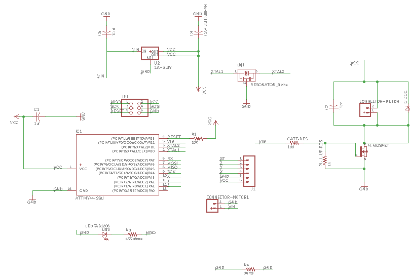
Designing in Eagle:
I had to check that I had the correct components in the libraries: the ones that are in Fablab's inventory.
| # | Name (library name) | Desctiption (Digikey) | Link DIGI-KEY |
|---|---|---|---|
| 1 | N - MOSFET | NDS355AN | Link |
| 2 | Head 3X2 pins(PINHD-2X3-SMD) | 609-5161-1-ND | Link |
| 3 | GREEN LED of 1.8V (LEDFAB1206) | 160-1169-1-ND | Link |
| 4 | Resistor 330 ohm for LED (RES-US1206FAB) | ||
| 5 | Gate resistor 100ohms (RES-US1206FAB) | 311-10.0KFRCT-ND | Link |
| 6 | Pull up/down resistor 1Kohm (RES-US1206FAB) | 311-10.0KFRCT-ND | Link |
| 7 | Unpolarized capacitor of 1uF (CAP-US1206FAB (CAP-US)) | 445-1423-1-ND | Link |
| 8 | Diode (DIODESOD123) | 497-5559-1-ND | Link |
| 9 | 2x01 Connector (CONN_02PTH3) |
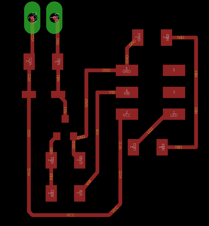
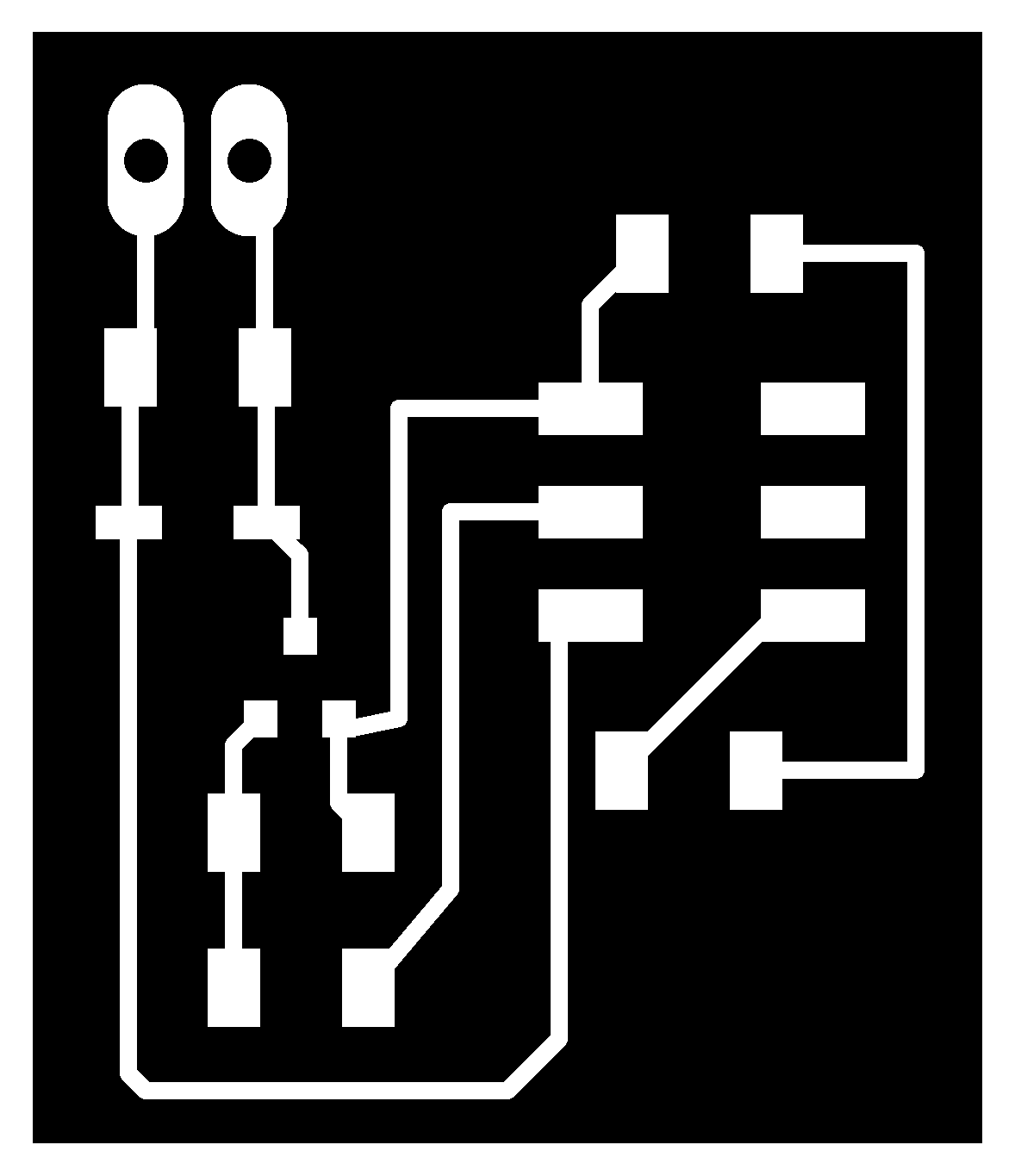
I looked for the different components in the library, the only ones that I had to look for in a library different from Fablab's one were the connectors. I make sure that those connectors had long-pads as I was going to use those ones. As you can see I had included an SPI connector, this is due to the fact that I will be using the Accelerometer board to do some tests. I will use the VCC and GND from that other board and I will use the MISO AND MOSI pins for the timers of the motor and a test LED.


Designing a mini-conector board:
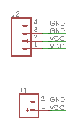
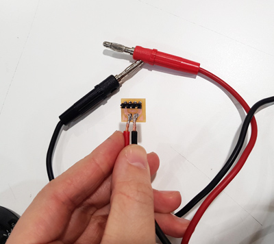
For now I will use a power supply as the VCC of this circuit, so I created a small board that only has pins for VCC and ground, and I solder the cables that will me connected to the power supply.

3. Milling and soldering:
In the same way as last week I used FabModules to mill my PCBs with the Modela 20. Steps that I follow are described in the Week 07.
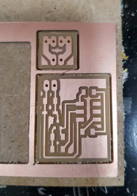
Once the two board were milled I started to solder the components to the board, playing attention to the ones that are directional like the diode and led. These were the resulting boards.
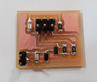
4. Programming the vibration motor:
For this week's assignment I studied how did Timers/Counters work to be able to use them instead of time delays. Dathasheet. First of all lets described what each of them do:
This two modules allow accurate program execution timing.
Then, next important thing to know is that we have two main registers when working with Timers, in the case of the 8-bit ones: the Timer/Counter (TCNT0) and Output Compare Registers (OCR0A and OCR0B).

- TCNT: corresponds to the register that will store the value that is being counted, in the case of the 8-bit registers it will be counting from [0, 255].
- OCR0A:B: contains the value that we will be comparing to the TCNT. The value that can take this register is described in the table below. If set to BOTTOM it will have 0 value; MAX will set the register to 255; and by setting it to TOP we will choose the value that we want it to have.

Modes of Operation:
We have four modes of operating:
- Normal mode (WGM02:0 = 0): this mode just counts up the maximum value, TOP value, and once it reaches it, it restarts from the BOTTOM.
- Clear Timer on Compare Match, CTC: In this mode we use the second register type, the counter is cleared to zero when the counter value (TCNT0) matches the OCR0A.
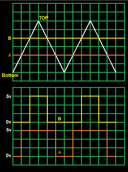
- Fast PWM mode: in the same way as the CTC, OCR0A:B has a value and when its the same as TCNT the timer will change from high to low. For example in a circuit with 5V, when reaching the value that we have establish the pin will change from 0V to 5V. Recommended when using a MOSFET. Explained a bit more into detail below.
- Phase correct PWM mode: similar to the previous one but in this case it uses a triangular waveform, so although the pulses are different sizes, the middle of them will coincide. It is indicated to circuits with a bridge.
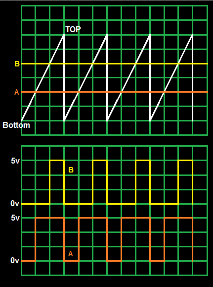
Prescaling:
As I also did in the Input week with the microcontroller, I need to set the prescaler to the value that I want to work with. I am working with 8Mhzs, and I want to leave it like this so I will set the registers to have No prescaling = (0,0,1).
(1 << CS02) (1 << CS01) (1 << CS00)
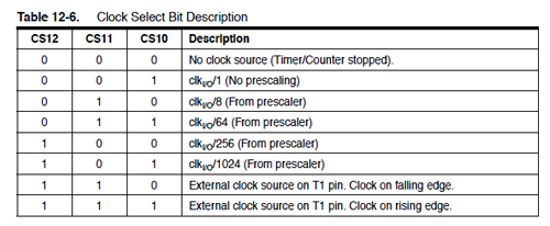 These bits are located in the TCCR1B register as shown in the next image:

Selecting the value for the comparative registers OCRA:B:
For calculating up to what value the counter needs to count for delaying a certain time we use two formules:
| Prescaler | Frequency | Time period | Timer count (8ms) |
|---|---|---|---|
| 1 | 8mil / 1 = 8Mhz | 0,000125 | 63999 |
| 8 | 8mil / 8 = 1Mhz | 0,001 | 7999 |
| 64 | 8mil / 64 = 125 Khz | 0,008 | 999 |
| 256 | 8mil / 256 = 31250 Hz | 0,032 | 249 |
| 1024 | 8mil / 1024 = 7812 Hz | 0,128 | 61,5 |
So, given the previous table for an example of 8ms, if we are using a 8-bit register we can only have up to 255 in the counter of the TCNT0 register, so we can use either a prescaler of 256 or 1024. For being more precise it will better to use the 256 one. Or if not with the 16-bit register we could even use a prescaler of 1.
Registers that I will be using:
As said before, I will be using the microcontroller of the Accelerometer board for this first test with the vibration motor. The pins that I am using are:
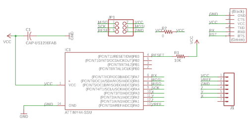
- Vibration motor : MOSI -> OC1A = PA6
- Test LED: MISO -> OC1B = PA5
We need to set the mode that we are going to use in the programming of the board. We will do this by changing the value of WGM13:10. Two of them are located in TCCR1A and the other two in TCCR1B.
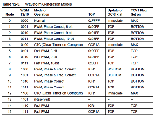
Then, to work with this modes we need to change the values of OC1A and OC1B according with what is described in the next table: The first one corresponds to the CTC mode that I will use and the second one to the PWM mode.
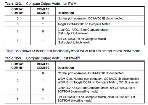
These bits are located in the TCCR1A register:

1. Code for using hardware CTC mode in a8-bit register: MOTOR
In this example I am using hardware CTC mode as I have the motor connected to the OC0B pin. What I am doing is I gave a TOP value to OCRA0, and whenever the timer reaches that value, the compare pins are configured to be togled. That means that when the timer reaches the TOP value, 249 for 8ms, the motor will be togled (changed from high to low and viceversa).
//
// motor.c
//
//    Modified by Victoria Peredo
//    Fablab CEU Madrid
//
//

//
// hello.speaker.45.c
//
// speaker PWM hello-world
//    square wave, pseudo-random frequency
//
// Neil Gershenfeld
// 11/14/10
//
// (c) Massachusetts Institute of Technology 2010
// This work may be reproduced, modified, distributed,
// performed, and displayed for any purpose. Copyright is
// retained and must be preserved. The work is provided
// as is; no warranty is provided, and users accept all
// liability.


#include <avr/io.h>
#include <util/delay.h>

//Defining the functions that will be used

#define output(directions,pin) (directions |= pin) // set port direction for output
#define set(port,pin) (port |= pin) // set port pin
#define clear(port,pin) (port &= (~pin)) // clear port pin
#define pin_test(pins,pin) (pins & pin) // test for port pin
#define bit_test(byte,bit) (byte & (1 << bit)) // test for bit set


//Defining the pin where is connected, PA6 in my case

#define MOSFET_pin (1 << PA6)
#define MOSFET_port PORTA
#define MOSFET_direction DDRA

void timer_init (){
   TCCR1B = (1 << CS12) | (0 << CS11) | (0<< CS10) |(1 << WGM12) | (0 << WGM13); // set timer 0 prescaler to  256

   TCCR1A =   (0 << WGM11) | (0 << WGM10); // (1,0) we are going to work in the CTC mode, for PWM mode (1,1)

   TCCR1A = (0 << COM1A1) | (1 << COM1A0);  //Stablishing togle OC1A on togle Compare Match, to switch on the motor

   TCNT1 = 0; // initialize counter register

   OCR1A = 31249;  //we use this register to store the TOP value that we will be comparing: 1000ms, 1sec
  }

int main(void) {

   clear(MOSFET_port, MOSFET_pin);
   output(MOSFET_direction, MOSFET_pin);

   timer_init();

   while (1) {

      //We don't need to put anything, everytime the timer reaches the desired value, 250 which corresponds to 8ms
      //The motor is going to be switched on and off.

      }
}
2. C Code for using hardware CTC mode in a 16-bit register: LED
Now I am also using hardware CTC mode but as the LED is connected to the 16-bit register we can have longer delaying times. We can count up to 65.536. Doing the calculations in the same way as before we have:
| Prescaler | Timer count (100ms) |
|---|---|
| 1 | 799.999 |
| 8 | 99.999 |
| 64 | 12.499 |
| 256 | 3124 |
| 1024 | 780,25 |
I will set the prescaler to 64 in order to be able to count until 100ms.
//
// ctc_led.c
//
//    Modified by Victoria Peredo
//    Fablab CEU Madrid
//
//
//
// hello.speaker.45.c
//
// speaker PWM hello-world
//    square wave, pseudo-random frequency
//
// Neil Gershenfeld
// 11/14/10
//
// (c) Massachusetts Institute of Technology 2010
// This work may be reproduced, modified, distributed,
// performed, and displayed for any purpose. Copyright is
// retained and must be preserved. The work is provided
// as is; no warranty is provided, and users accept all
// liability.


#include <avr/io.h>
#include <util/delay.h>

//Defining the functions that will be used

#define output(directions,pin) (directions |= pin) // set port direction for output
#define set(port,pin) (port |= pin) // set port pin
#define clear(port,pin) (port &= (~pin)) // clear port pin
#define pin_test(pins,pin) (pins & pin) // test for port pin
#define bit_test(byte,bit) (byte & (1 << bit)) // test for bit set


#define cycle_delay() _delay_us(2) // cycle delay
#define current 150 // PWM current
#define off 255 // PWM off

//Defining the pin where is connected, PB2 in my case

#define LED_pin (1 << PA5)
#define LED_port PORTA
#define LED_direction DDRA

void timer_init (){

   TCCR1B = (1 << CS12) | (0 << CS11) | (0<< CS10) |(1 << WGM12) | (0 << WGM13); // set timer 0 prescaler to  256

   TCCR1A =   (0 << WGM11) | (0 << WGM10); // (1,0) we are going to work in the CTC mode, for PWM mode (1,1)

   TCCR1A = (0 << COM1B1) | (1 << COM1B0);  //Stablishing togle OC1B on Compare Match, to switch on the motor

   TCNT1 = 0; // initialize counter register

   OCR1A = 31249;  //we use this register to store the TOP value that we will be comparing: 1000ms, 1sec

   }

int main(void) {

   clear(LED_port, LED_pin);
   output(LED_direction, LED_pin);

   timer_init();

   while (1) {

      //We don't need to put anything, everytime the timer reaches the desired value, 12499 which corresponds to 100ms
      //The led will be switched on and off.

      }
}
3. C Code for using hardware PWM mode in a 8-bit register: MOTOR
Introduction to PWM:
C code to enable the PWM timer in the OC0B pin to control the motor. The motor runs ideally at 13000rpm/min when connected to a 3V supply. When we establish a 1.5V supply, the rpm will reduce to the half (6500rpm).
But what happens when instead of giving a constant power supply we give pulses:

As the motor doesn't start and stop immediately, when we give pulses, it won't have time to reach the total speed but neither to stop completely, this means that the motor will be all the time switched on but at a lower speed.
The previous picture is an example of a motor working at 12V, if we set those pulses it will result in the motor working as if the power supply was 6V.
If we now reduce the time in the high state it will mean reducing speed.
Generating PWM with hardware:
In this code I am setting the PWM duty cycle to be 75% of the total, i.e, 75% of the total 3V = 2.25V.
//
// motor_pwm.c
//
//    Modified by Victoria Peredo
//    Fablab CEU Madrid
//
//
//
// hello.speaker.45.c
//
// speaker PWM hello-world
//    square wave, pseudo-random frequency
//
// Neil Gershenfeld
// 11/14/10
//
// (c) Massachusetts Institute of Technology 2010
// This work may be reproduced, modified, distributed,
// performed, and displayed for any purpose. Copyright is
// retained and must be preserved. The work is provided
// as is; no warranty is provided, and users accept all
// liability.


#include <avr/io.h>
#include <util/delay.h>

//Defining the functions that will be used

#define output(directions,pin) (directions |= pin) // set port direction for output
#define set(port,pin) (port |= pin) // set port pin
#define clear(port,pin) (port &= (~pin)) // clear port pin
#define pin_test(pins,pin) (pins & pin) // test for port pin
#define bit_test(byte,bit) (byte & (1 << bit)) // test for bit set


#define cycle_delay() _delay_us(2) // cycle delay
#define current 150 // PWM current
#define off 255 // PWM off

//Defining the pin where is connected, PA6 in my case

#define MOSFET_pin (1 << PA6)
#define MOSFET_port PORTA
#define MOSFET_direction DDRA

void pwm_init (){

  output(LED_direction, LED_pin);

  TCCR1B  |= (0 << CS12) | (1 << CS11) | (0<< CS10) | (0 << WGM13) |(1 << WGM12) ; // set timer to prescaler 8

   // set timer to prescaler 1 and Fast PWM
  TCCR1A |= (1 << COM1A1) | (0 << COM1A0);  //Non- inverted mode PWM
  TCCR1A  |= (1 << WGM10) | (0<< WGM11);    //  8 bit PWM mode for the 16-bit timer

   }

int main(void) {


   pwm_init();

   uint8_t brightness;

   while(1)
   {


     for (brightness = 0; brightness < 255; ++brightness)// increasing the speed
     {

         OCR1A = brightness; //in this case the duty cycle is going to be modified by the brightness variable


         _delay_ms(10); // we add a delay to be able to see how the speed changes
     }

     for (brightness = 255; brightness > 0; --brightness)// now the loop is going the other way round
     {

         OCR1A = brightness;

         _delay_ms(10);
     }


   }
}
4. C Code for PWM mode in a 16-bit register: LED
I followed a tutorial for working with PWM, the same place that I got some of the previous image from: this page. Here they do a similar program as one of Neil's to reduce the LED brightnes using a for loop with a counter.
//
// led_pwm.c
//
//    Modified by Victoria Peredo
//    Fablab CEU Madrid
//
//
//
// hello.speaker.45.c
//
// speaker PWM hello-world
//    square wave, pseudo-random frequency
//
// Neil Gershenfeld
// 11/14/10
//
// (c) Massachusetts Institute of Technology 2010
// This work may be reproduced, modified, distributed,
// performed, and displayed for any purpose. Copyright is
// retained and must be preserved. The work is provided
// as is; no warranty is provided, and users accept all
// liability.

#define F_CPU 8000000L
#include <avr/io.h>
#include <util/delay.h>

//Defining the functions that will be used

#define output(directions,pin) (directions |= pin) // set port direction for output
#define set(port,pin) (port |= pin) // set port pin
#define clear(port,pin) (port &= (~pin)) // clear port pin
#define pin_test(pins,pin) (pins & pin) // test for port pin
#define bit_test(byte,bit) (byte & (1 << bit)) // test for bit set


//Defining the pin where is connected, PB2 in my case

#define LED_pin (1 << PA5)
#define LED_port PORTA
#define LED_direction DDRA

void pwm_init (){

  output(LED_direction, LED_pin);

  TCCR1B  |= (0 << CS12) | (1 << CS11) | (0<< CS10) | (0 << WGM13) |(1 << WGM12) ; // set timer to prescaler 8

   // set timer to prescaler 1 and Fast PWM
  TCCR1A |= (1 << COM1B1) | (0 << COM1B0);  //Non- inverted mode PWM
  TCCR1A  |= (1 << WGM10) | (0<< WGM11);    //  8 bit PWM mode for the 16-bit timer


   }

int main(void) {


   pwm_init();

   uint8_t brightness;

   while(1)
   {


     for (brightness = 0; brightness < 255; ++brightness)// increasing brightness
     {

         OCR1B = brightness; //in this case the duty cycle is going to be modified by the brightness variable


         _delay_ms(10); // we add a delay to be able to see the LED changing
     }

     for (brightness = 255; brightness > 0; --brightness)// now the loop is going the other way round
     {

         OCR1B = brightness;

         _delay_ms(10);
     }


   }
}
Video of the LED flashing with PWM configuration:
5. Designing the first prototype of the inclination sensor board:
This week I had designed a board that will be part of the final project where I have included:
- Accelerometer
- Vibration motor
- Bluetooth
- External battery
I talk about the 'first' prototype as to fit all the components I ended up with a quite big board. I would like to reduce its size at some point. I used the scheme of the accelerometer board that I designed in the Input week and also the one of the vibration motor of the Output week.
I will use an external battery of 3.7V and my components have the following voltage ranges:
· Motor: 2-3.6V
· Bluetooth: 2.5-3.3V
· Accelerometer: 1.8-3.6V
· Microcontroller: 1.8-5.5V
So I needed to include in my design a regulator for lowering the incoming voltage I used the ZLDO 3.3V 1A one.

Once I had all the components I switched to the Board and I tried placing them as good as posible. I used the Autoroute at one point as I was unable to join them all together. I eneded up adding some 0ohms resistors to be able to communicate some of the components:

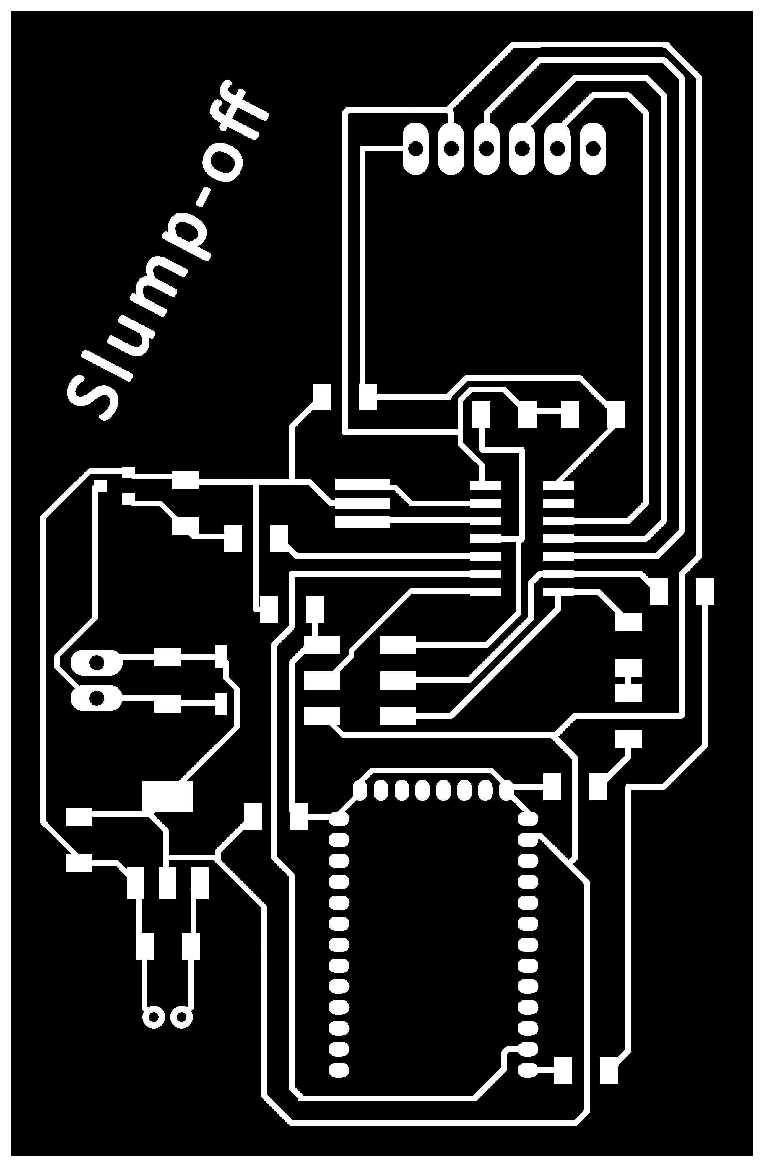

Problems!
Following the steps of the Seventh Week for milling a PCB using mods with the modela I milled this board and I solder the components. I had a little problem there... I didn't realize that the holes for the battery connector were not going to be milled as their diameter was smaller than the tool one. So, as I had separate the board from the base already I had to do the holes using a portable milling machine.
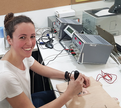
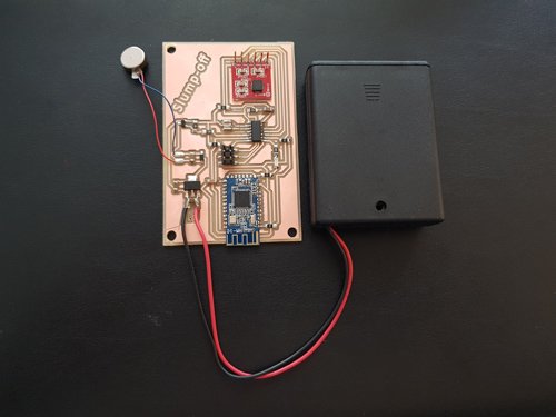
More problems! I manage to put the pins of that same component that was suppose to be for the battery connector in the wrong way so when connecting the battery GND will be connected to VCC and vice versa. So, I ended up soldering the cables of a 4 battery adaptor to the board to be able to work with it.
6. Second prototype of the inclination sensor board:
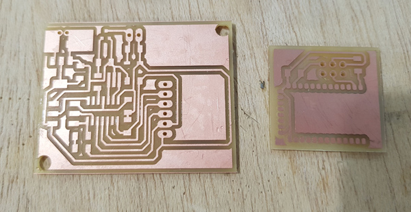
As for the final project I wanted to create a smaller board for being more confortable when wearing it on top of the neck I re-designed it by spliting it in two boards. The first one will have the accelerometer and microcontroller, and the second one, that will go on top, the Bluetooth.
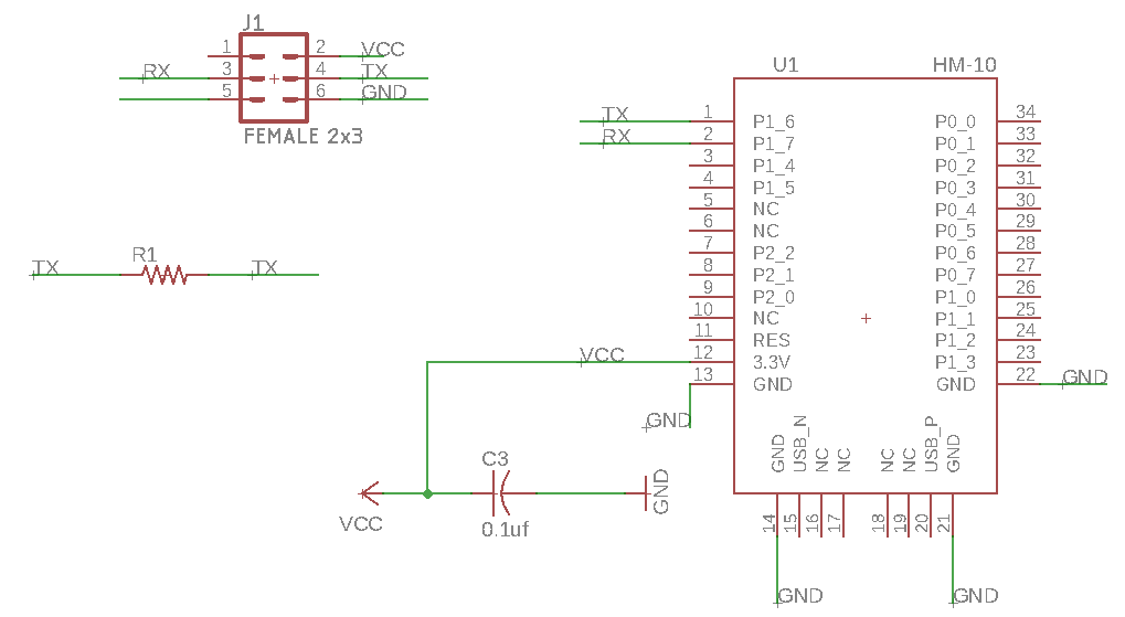
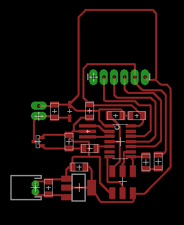
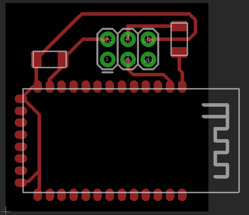
Milling and soldering
Once it was designed I exported the images and I cut it with the Modella using mods.
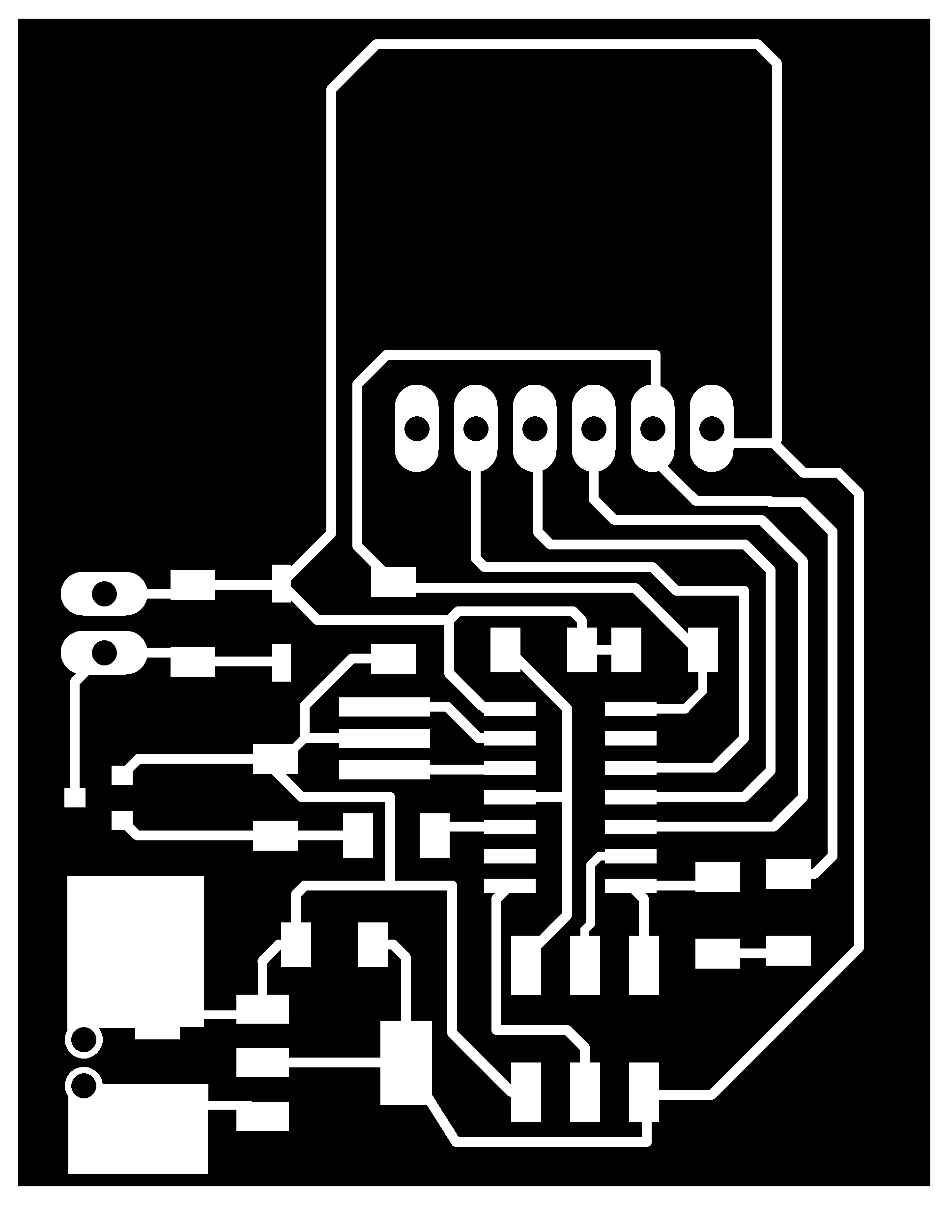

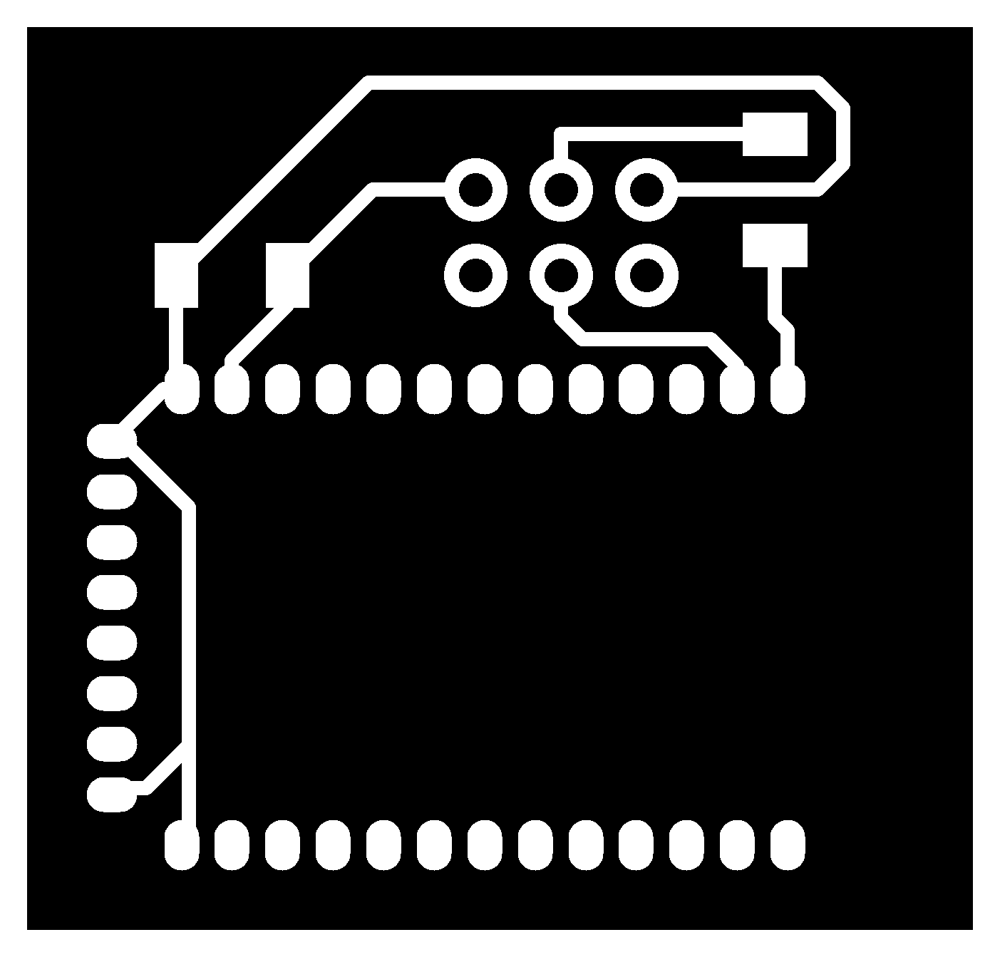

I checked that I didn't have any short circuits in the board and I solder the components. I used the components that I had in the other board, so I had a bit of trouble when soldering the accelerometer as the wholes of the connections had a bit of solder on them.
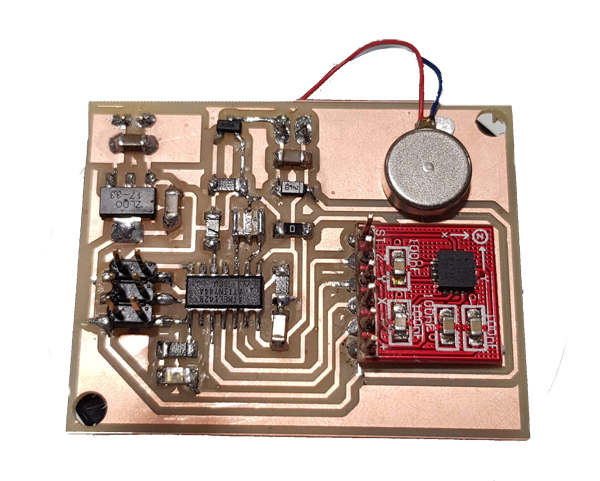
7. Programming the board:
Once I had the board I loaded a .c program that turns on the vibration motor.
PROBLEM!
I had a lot of trouble with this because I had connected the motor to the PB2 pin of my ATTiny 44 microcontroller and I was programming it to turn it on and it would work. After checking that the programming was correct we checked that the 5V of voltage were reaching that pin and they were not. We changed the microcontroller to a new one and we kept on having the same problem. The problem ended up being that all the microcontrollers in that packet had the PB2 pin broken! We did a bridge with the pin that was next to it that was not connected to anything and it was finally working!
Code:
//
// motor_ctc.c
//

//
//
//
// hello.speaker.45.c
//
// speaker PWM hello-world
//    square wave, pseudo-random frequency
//
// Neil Gershenfeld
// 11/14/10
//
// (c) Massachusetts Institute of Technology 2010
// This work may be reproduced, modified, distributed,
// performed, and displayed for any purpose. Copyright is
// retained and must be preserved. The work is provided
// as is; no warranty is provided, and users accept all
// liability.
//    Modified by Victoria Peredo
//    Fablab CEU Madrid


#define F_CPU 8000000UL
#include<avr/io.h>
#include <util/delay.h>

//Defining the functions that will be used

#define output(directions,pin) (directions |= pin) // set port direction for output
#define set(port,pin) (port |= pin) // set port pin
#define clear(port,pin) (port &= (~pin)) // clear port pin
#define pin_test(pins,pin) (pins & pin) // test for port pin
#define bit_test(byte,bit) (byte & (1 << bit)) // test for bit set


#define cycle_delay() _delay_us(2) // cycle delay
#define current 150 // PWM current
#define off 255 // PWM off

//Defining the pin where is connected, PA6 in my case

#define MOSFET_pin (1 << PA7)
#define MOSFET_port PORTA
#define MOSFET_direction DDRA


void timer_init (){
   TCCR0B  |= (1 << CS02) | (0 << CS01) | (0<< CS00) |(0 << WGM02) ; // set timer 0 prescaler to  256

   TCCR0A  |=  (1<< WGM01) | (0 << WGM00);    //  8 bit PWM mode for the 16-bit timer
   // set timer to prescaler 1 and Fast PWM
   TCCR0A |= (0 << COM0B1) | (1 << COM0B0);  //Non- inverted mode PWM
   TCNT0 = 0; // initialize counter register

   OCR0B = 249;  //we use this register to store the TOP value that we will be comparing: 1000ms, 1sec
}
int main(void) {

   clear(MOSFET_port, MOSFET_pin);
   output(MOSFET_direction, MOSFET_pin);

   timer_init();

   while (1) {

      //We don't need to put anything, everytime the timer reaches the desired value, 250 which corresponds to 8ms
      //The motor is going to be switched on and off.

      }
}
Next weeks I will be adding the condition for the motor to vibrate whenever the accelerometer is sensing a bad angle.
Group assignment:
Group assignment pageFor this week's group assignment we needed to measure the power consumption of the output device that we were using. For the motor that I used this week I needed to supply 3.3V so when using the power supply machine I also measured what was the power consumption. We tested this when the motor was set to the minimum and maximum to check what was its maximum. In the next two pictures you can see that when the motor was off the power consumption was 0A and when it was on it was 0.08A.
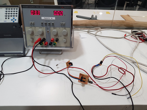
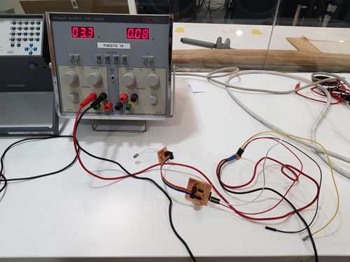
Measuring with the multimeter
We also measured the power consumption of a DC motor using both the power supply and the multimeter. For doing so we have to connect them in the following way:
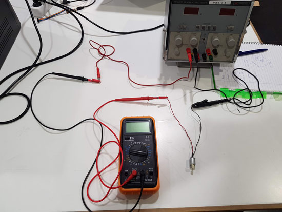 The GND of the power supply has to be connected to the ground cable of the DC motor. Then we connect the red probe to the current connection, we first started by measuring with the biggest one, the 10A one. It is always bettero to start with the biggest one and then if you see that your consumption is less than that you can chnge to the 500mA max one. This red probe will be connected to the other cable of the motor. Finally, the red probe of the multimeter has to be connected to the VCC of the power supply.
Before connecting everything we made sure that the power supply was stablish to the one we wanted, 5V for the DC motor. Once the whole thing was ready we switched on and we measured the consumption.
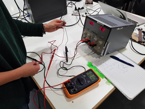
In this case the consumption was in 0.10 ams so we could change the multimeter probe to the 500mA position. Then we also changed the A wheel to 200m. By doing this we can be more precise with the measuring. You can see in the next video that it was consuming around 98mA.