(id='design')
I think winemaking is a good fit to Bioacademy and a good crossover subject for Fabacademy. I wanted this week to be pertinent to my final project, which is a winemaking project. I suppose I should provide some information about enology before I discuss digital technology. Enology is the science of fermentation. In the simplest of terms, wine is made when you add yeast to a container of liquid, usually grape juice, add yeast, and let the yeast metabolize the sugar while deprived of oxygen, which will produce alcohol. Typically a winemaker will have the container filled between 80 and 90% full. A little room is left at the top of the tank for foaming. When the yeast start "cooking", they consume the oxygen in the just closed tank, and multiply quickly, producing carbon dioxide as a byproduct. Once the oxygen runs out, the yeast start producing both alcohol and carbon dioxide (CO2). After fermentation is complete, the tank is stored for dirrerent lengths of time. Tanks can be opened for test samples. Tanks are moved. Tanks have gasketed closures. Wine is often "tacked off" the lees into a different tank. Sometimes tanks are opened so that fining agents can be added to wine. There are many events during the winermaking process where air can re-enter a fermentation tank (fermenter), or aging tank. When wine is exposed to air for long periods of time, the wine can oxidize, requiring sulfites to be added. The wine can even go bad, turning to vinegar. So, in general, oxygen is the winemakers' enemy. A winemaker often doesn't know if the wine is exposed to oxygen, which is a common dilemna in a winery.
With "Input Week", my first thoughts were to find a sensor which would be useful in my final project. I had been questioning what sensors are available to me, or if I could make one that is reliable. There is nothing of the sort offered at winemaking supply houses. Looking around Amazon and Ebay, I found many CO2 sensors, but nothing under O2 sensor, unless it was part of a complete device. After seeing an abundance of CO2 sensors, and no O2 sensors, I started to doubt my whole final project. Another question I began posing to myself is what would I be sensing? Should I still try to sense the O2, or should I try to sense the inert gas, such as CO2? I really didn't like the idea of using CO2 gas, because I would like to be able to indroduce the gas through a sampling valve and bubble it through the bottom of the liquid column, thereby agitating the wine while it is purged. If I used CO2, this could end up dissolving CO2 in the wine, causing it to be effervescent. Effervescence in a still wine is considered a fault, and I was trying to avoid that. Nevertheless, I could add the gas to the top of the tank as a last resort.
I had other reasons to use an O2 sensor. My preference would to be proof-positive and sense for O2. A lot of this depended upon what kind of sensor I could find. If I could find a good O2 sensor, I would have the option of purging with a variety of gasses. If I used a CO2 sensor, I would be restricted to only using CO2 as my purge gas. Also, if the CO2 gas was not completely pure, I would most likely get a false positive of the presence of O2. So I bought some CO2 sensors and continued to look of O2 sensors. I guess I was spiral searching. I sometimes call this burning the candle from both ends. So my whole Input week was driven by what type of sensor I could find.
During the 2017 cycle, we did Output Week before Input week, so I progressed with my output board first, which was a hello-world, modified to run a solenoid valve which would be needed to control purge gas for the final project. By the time we moved on to Input Week, I was figuring out how I could get everything built onto the minimum number of boards, and if possible, all on one board. I was surprised by the scarcity of O2 sensors on the market. Many of the O2 sensor/testers on the market are proprietary. Perhaps building the actual sensor could be a possible "next project".
At this point, I was spiraling between Output, Input, Final Project, and back to Output, and trying to devise how to get it all on one board, if possible. At the same time, I am evaluating sensors that I have no prior experience with from vendors I have never heard of. I was faced with a testing/troubleshooting dilemna of not knowing if something was going to work or not, and to compound matters, not knowing WHICH thing was not working. Most of the CO2 sensors were analog sensors. I started reading the data sheet for the Microchip/Atmel Tiny44 so to see where to fit an analog line on my hello-world board.
I searched through Digikey and saw some Honeywell low-tempersature O2 sensors, model MF010. The cost of the sensor was over US$3000, which didn't fit the budget. In addition, this type of sensor utilizes the concept of partial pressure (electromechanical) which is rather slow and innacurate, and a bit of a power pig. The Honeywell MF010 sensor requires the user to calibrate the device. The sensor's primary mission is for combustion controls.
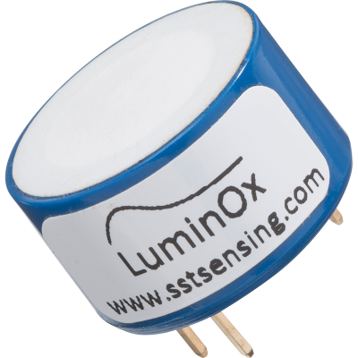
Part of the instrution for the Final Project was to keep the cost within "hundreds" of dollars, not "thousands". So I kept looking and I finally found something which I would have to procure from outside the United States. It is called the Luminox LOx2. The Luminox LOx2 is manufactured by SST Sensing LTD, of Coatbridge UK. The sensor is an optical sensor, which means long service life. It'd primsry mission is to support devices in the life-sciences industrey. That seemed like a better fit for my project. The Luminox is an optical based sensor, and is purported to last >5 years under normal conditions. It communicates serially using 3.3V RS232 protocol, and also requires a seperate 5VDC to power the optics.
Cost: apx $90. Available from manufacturer, or from Amazon UK.
Pertinent information from the data sheet, which can be found here: http://www.sstsensing.com/wp-content/uploads/2017/07/DS0030rev13_LuminOx.pdf. Information from the manufacturer:
FEATURES:
Fluorescence–based optical technology, NOT electrochemical
•Contains no hazardous materials; RoHS & REACH compliant
•Connects directly to a microcontroller without any additionalcircuitry
•Factory calibrated
•High accuracy
•Maintenance freeTECHNICAL SPECIFICATIONS
Supply voltage (Vs) 4.5—5.5VDC
Supply current (ls) <7.5mA (streaming one sample per second), <20mA Peak
Output Type 3.3V TTL level UART
Temperature
Operating: -30°C to +60°C
Storage: -30°C to +60°C
Humidity 0—99% Rh (non-condensing)
Barometric pressure range LOX-01 100—1400mbar
LOX-02 500—1200mbarOUTPUT VALUES
Oxygen range (LOX-02) 0—25% O2
Oxygen pressure range 0—300mbar ppO2
Response time T90 < 30s (typical)
Accuracy
ppO2 < 2% FS
Temperature Indication only
Pressure (LOX-02) ±5mbar
O2 (LOX-02) Determined by ppO2 & pressure accuracy
Resolution
ppO2 0.1mbar
Temperature 0.1°C
Pressure (LOX-02) 1mbar
O2 (LOX-02) 0.01%
Lifetime >5 years
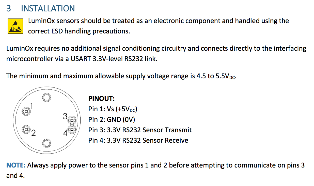
The issue I see with this sensor is that I will need to supply 5 volts DC which is different than my output board, which is 3 volts DC. Pins 1 and 2 basically heat the sensor and illuminate a UV LED and power an embedded processor. Pins 3 and 4 communicate at 3.3V with RS232 serial, 9600 baud rate.
In my final project I am planning on using the solenoid board I built earlier for Week 11: "Output Devices" (2017 cycle). This board is based on an Atmel ATTiny44 and regulates 12 volts DC down to 5 volts. The board was complicated as it was, and I utilized solder pads and flying leads which eventually failed. My next revision utilizes headers for lead connections, and is discussed later on this page. I expect utilizing headers will make things more complicated to route traces to headers. I had the thought of integrating the Hello-Solenoid onto the same board as the Hello-Input. However, after starting the design process, I came to the realization that I would have to get into multi-layer prototyping, to get more components on the board. I don't have experience with multi-layer boards. My board mill has the abilility to do them, so I will add that to the "future things to evaluate" list. With a multilayer card, I think I can add more voltage regulators on the card and an additional Tiny44 to integrate the Hello-Solenoid board on the same card. Plus, I have to think about serial communication to the sensor, and get all of it to fit into the package size of a double-gang junction box. I will need some serious instruction later on in order to do this.
For now, better to divide and conquor. This will make development and testing easier. I will need to do things on seperate boards and connect them with wires. So I added the slide-switches, the two buttons and a solder pad between GPIO0 and GPIO2 (SDA) as a bridge to enable pin mode. I also would like the board to eventually, possibly, be located somewhere near a central gas supply and manifold and able to communicate with a server or IoT application. So, I thought it would be a good idea to use an ESP-12E instead of the ATTiny44 which I have been using.
I decided to try another spiral and swap out the Tiny44 for an ESP-12E module on my Hello-World board. I added two buttons and two micro slide-switches, anticipating I would need them for flashing the ESP-12E module. . I configured this design with serial communication, including I2C in mind. The ESP-12E requires more traces to get the board up and running. It also requires a special process to flash the module, which I felt could be handled by microiswitches. Incorporating the microswitches as well as all the inputs and outputs made the board a bit crowded. In order to use the Luminox O2 sensor, I would need to run RS-232 in software, or use a hardware UART circuit. I would guess that UART hardware would be faster than doing serial communication on the chip.
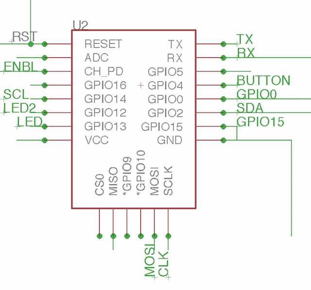
In order to design this chip, I had to add a ESP8266 library to Eagle, and also an ESP8266 library to the Arduino IDE. The source I used for the Eagle library is http://www.esp8266.com/viewtopic.php?p=8868. I have attached the actual library file to this page. There are many variations of the ESP8266, and each manufacturer has it's own interpretation of them. The best place I found for documents was at www.espressif.com. There, you can find datasheets and procedures for this family of modules. The following board was designed with the ESP-12E, which has 2.4GHz WiFi built into the the module. The antenna for the WiFi is built into the module as a serpentine trace. I deliberately left this trace hanging off the edge of the board so that the antemnna wouldn't be shielded by the underlying copper.
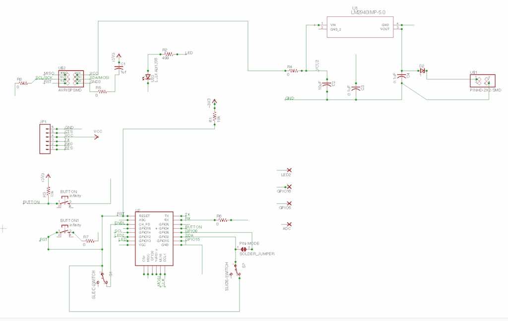
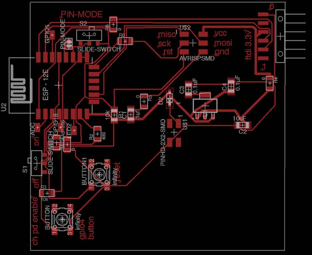
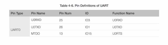
Above is an image of the Eagle .brd file for the ESP evolution of the Hello-xxx board. Espressif , the manufacturer of the ESP-12E, has a datasheet which can be found here: https://www.espressif.com/sites/default/files/documentation/0a-esp8266ex_datasheet_en.pdf . From the datasheet, you can get information about pinouts for different serial communication. The ESP supports two UARTS, UART0 and UART1. UART0 configuration is below:
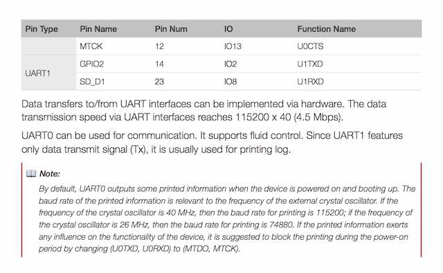
Configuration for UART1 below:
Significant Pinouts:
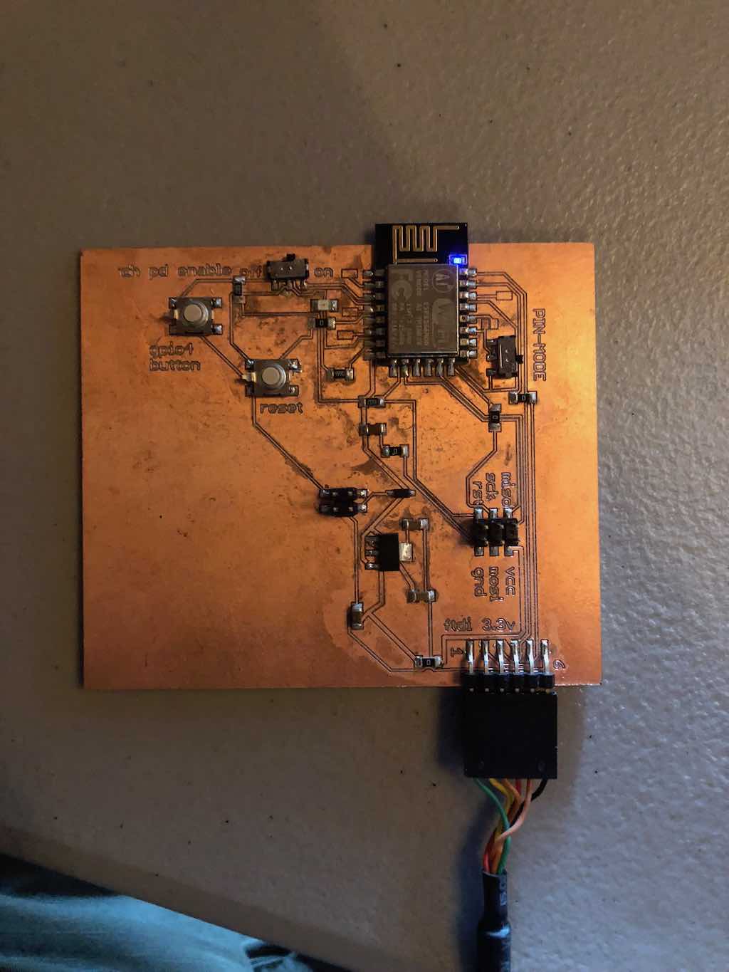
The hello-world board with the ESP-12E was milled out on my LPKF Board Mill which I described in my Week15, Embedded Networking. The traces looked good. I had difficulty with the alignment of the ESP-12E module to the board. The module is not a true surface mount. There are small holes covered with solder around the periphery of the module. The technique I used was to place a small piece of double-stick tape underneath the module and line it up to my board as close as possible by hand. I then tacked down two opposite pinouts just to keep the module from moving around. I think I may have been over-ambitious trying to make this board as big as I did. I am not confident in the soldering job I did on the module. The board is pretty complicated. I think it's time for a different strategy. Perhaps start out with a simpler design just to get familiar with soldering and testing the ESP-12E module?
The FTDI cable identifies itself on my Windows 10 laptop as COM11. In the Arduino IDE, I set up the board with
I plug the board into the FTDI cable. A blue LED lights up on the ESP-12E. When I perform "Tools - Get Board Info", I get this message:
BN: Unknown Board
VID: 0403
PID: 6001
SN: Upload any sketch to obtain it
This is probably just the FTDI cable reporting to the laptop. After some lengthy troubleshooting, I cannot figure out how to flash the ESP-12E, and I don't have anyone out here in northern Ohio to ask.
At this juncture, I felt it was better to investigate a different ESP8266 module which has the UART built into the module, such as an ESP8266-Amica. I may still use my 12E board for other development, but it is a dead-end for RS-232 communication to the Luminox sensor.
During Networking and Communications week (Week15), I had also reviewed the ESP8266 series of modules called LUA ESP-12E "Amica". At the time, they were under $9 on Amazon, single quantity, including shipping. Very reasonable. They are 3.3v based, and have a hardware UART, which seems like a good fit for the Luminox O2 sensor. I figure I will make a sensor shield which combines the ESP and the Luminox. Then the shield will connect to the hello-solenoid board which will have one input available to communicate with the shield. The construction of this shield is covered in my final project page, and this covers using the Luminox O2 sensor as an input. That shield incorporates a newer version of my Hello-Solenoid board, the rev13 version, which I developed after "Output Devices", Week13. It was made to work with the ESP8266 module/shield combination specifically for the final project, which ties in the Luminox Sensor. The earlier version of the Hello-Solenoid board is described in Week13. It does not incorporate the Input Sensor. I eventually would like each board communicating through a LAN and having a server operating the logic. In my final project, both boards are self-contained in one unit. In a winery, it may be advantageous to have a bank of solenoids feeding off a gas manifold, and have the Oxegen sensors distributed throughout the winery at the tank locations. Eventually, I would like to make the hello-solenoid board connected to a network/server combination. For now, that thought will have to wait for the next spiral development pass.
Eagle schematic file for hello8266 board: hello8266-i2c-r4-2017-05-21-00.sch
Eagle board file for hello8266 board: hello8266-i2c-r4-2017-05-21-00.brd
LPKF Mill file for hello8266 board: hello8266-i2c-r4-2017-05-21-00.cmp
Eagle Library for ESP8266: ESP8266-Eagle_Library-master.zip
Credit for the Eagle Library go to Skutch; acquired from http://www.esp8266.com/viewtopic.php?p=8868
Olimex MOD-WIFI-ESP8266-DEV board by https://github.com/rene79
There is a library for the ESP8266 family of modules which can be added to the Arduino IDE. You do this from the Arduino IDE application by navigating as follows:
At this point, the Arduino IDE needs to activate the library from the Tools menu.
You should have the ESP family of modules available to you in the IDE.
The Hello-Solenoid board is a descendant from the project we did on Week 8. This is a better version which addresses some of the failures of the earlier project. Designed using Eagle version 7.70 (Mac). I am using GPIO 11 as the input port which will connect to the sensor shield. The oxygen sensor requires an RS232 connection via a 3.3V UART which is found on the ESP module.
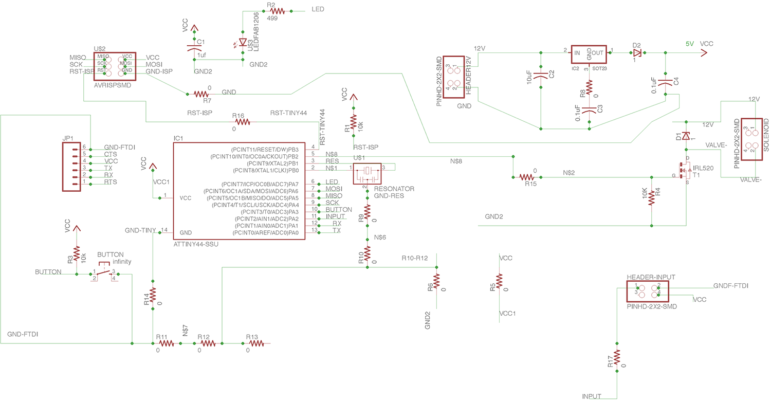
Significant pinouts:
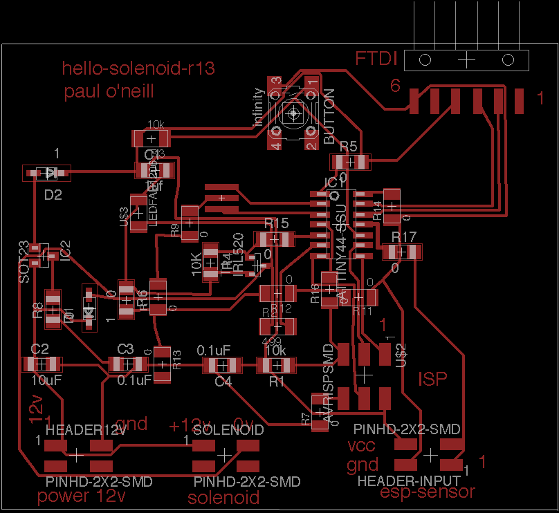
Please refer to "Electronics Design", Week7, where I milled the board for that week in a circuit board mill called LPKF. The hello-solenoid-rev13 board was milled in the same machine using the same process. I use the CAM processor to generate a Gerber file for this mill.
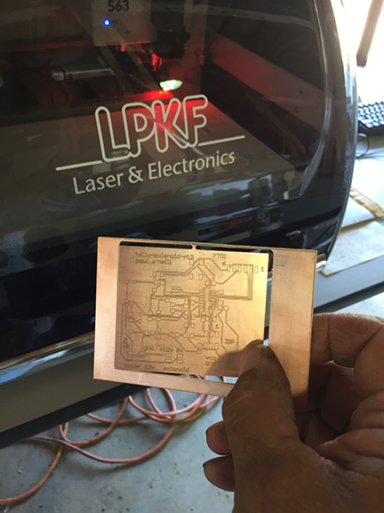
Convert Eagle file to Gerber file and cut on my LPKF board mill. The LPKF Protomat S63 mill has a 60,000 rpm spindle, a 15 tool automatic toolchanger, and can be calibrated for automatic milling width adjustment (trace width).
(id='files')
CAM files for the LPKF Mill:
(id='problems')
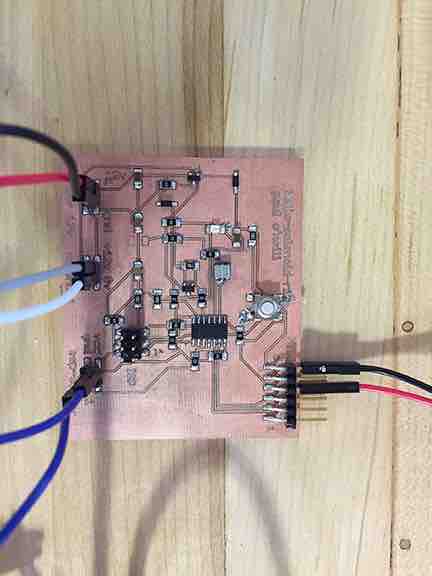
Stuff the board and solder it up. Instead of solder pads, I decided to use headers. I kept having issues with my earlier Hello-Solenoid board where the solder pads for flying leads would tear out. I also decided to use the TEXT feature of Eagle to mill out legends for these headers. It is easy to make a mistake hooking a wire to the wrong pin. With eight (8) discreet wires to hook up, legends on the headers is very helpful, but not foolproof. Care still needs to be taken.
(id='programming')
I adapted this program from one of the example sketches included with the Arduino IDE for my hello-solenoid-r13 board. I added the solenoid to act in parallel to the LED. This board is based on the ATMEL ATTiny44 which is 5 volt based. The solenoid valve is 12 volts. In previos boards, I cooked the voltage regulator because the board was being powered from two sources, which "goofed" up the voltage regulator and caused it to fail. I added diodes to protect the voltage regulator. Nevertheless, I use a programmer which has the ability to power, or not power the board. I had good success with the "Sparkfun AVR pocket programmer" available through Digikey, part number 1568-1080-ND for $14.95. I highly recommend it. It is convenient to leave power off and keep debuigging your board without having to worry about frying a voltage regulator. The data sheet helpedme translate from Arduino pinouts to ATTiny44 pinouts. I placed comments after eachline in the program to show how I mapped the pinouts.
---------------------------------------------------------------------------------------------------------------
#include <SoftwareSerial.h>
/*
Blink
Turns on an LED on for one second, then off for one second, repeatedly.
Most Arduinos have an on-board LED you can control. On the UNO, MEGA and ZERO
it is attached to digital pin 13, on MKR1000 on pin 6. LED_BUILTIN is set to
the correct LED pin independent of which board is used.
If you want to know what pin the on-board LED is connected to on your Arduino model, check
the Technical Specs of your board at https://www.arduino.cc/en/Main/Products
This example code is in the public domain.
modified 8 May 2014
by Scott Fitzgerald
modified 2 Sep 2016
by Arturo Guadalupi
modified 8 Sep 2016
by Colby Newman
*/
const int LED = 7; //TINY44 PA7
const int SOLENOID = 8; //TINY44 PB2, IDE 8, pin 5
const int ESP = 2; //TINY44 PA2, IDE 2, pin 11
const int BUTTON = 10; //TINY44 button connected to PA3, IDE 3, pin 10
// the setup function runs once when you press reset or power the board
void setup() {
// initialize digital pin LED_BUILTIN as an output.
pinMode(LED, OUTPUT);
pinMode(SOLENOID, OUTPUT);
pinMode(ESP, INPUT);
pinMode(BUTTON, INPUT);
// Serial.begin(9600);
}
// the loop function runs over and over again forever
void loop() {
int ESPValue=digitalRead(ESP);
// Serial.println(ESPValue);
if (ESPValue > 0) {
delay(1);
digitalWrite(LED, HIGH);
//digitalWrite(INPUTLINE, HIGH);
digitalWrite(SOLENOID, HIGH);
} else {
digitalWrite(LED, LOW); // turn the LED off by making the voltage LOW
digitalWrite(SOLENOID, LOW);
/*
digitalWrite(LED, HIGH); // turn the LED on (HIGH is the voltage level)
// digitalWrite(INPUTLINE, HIGH);
digitalWrite(SOLENOID, HIGH);
delay(2500); // wait for a second
digitalWrite(LED, LOW); // turn the LED off by making the voltage LOW
// digitalWrite(INPUTLINE, LOW);
digitalWrite(SOLENOID, LOW);
delay(1000); // wait for a second
*/
}
}
---------------------------------------------------------------------------------------------------------------
I attached the plus and minus of the 12V HEADER (power 12v) to a Tenma 72-8350A Switching Mode Power Supply. I set the current limit to 0.5 amp, and the voltage to 12V. I next took my multimeter, a Fluke 117, and used banana clips to connect the leads to SOLENOID HEADER, pins 1 and 2. I ran the above program and the meter did range back and forth from 0 volt to 12 volt. The board works. The part of the program which sends the input line high and low is commented out for when you don't need the solenoid running. Kind of crude, but works while troubleshooting.