Design appropriate objects within the limitations of 3 axis machining
Demonstrate workflows used in mould design, construction and casting
My final project includes packaging my device into a cover which can be adapted to an ordinary junction box. I thought it might be helpful to start 3-D modeling my package and design a quick-prototype utilizing closed cell foam, machine it on a cnc router, and cast the model using Smooth-on Vytaflex-20 urethane epoxy. I use Smooth-on often to make "skins" or stamps for decorative concrete work. It is an impressive material.
I plan on milling the mold using acetal at a later date and perhaps use a more complicated, multi-piece mold which will be easier to make, and also easier to release the part
(id='design')
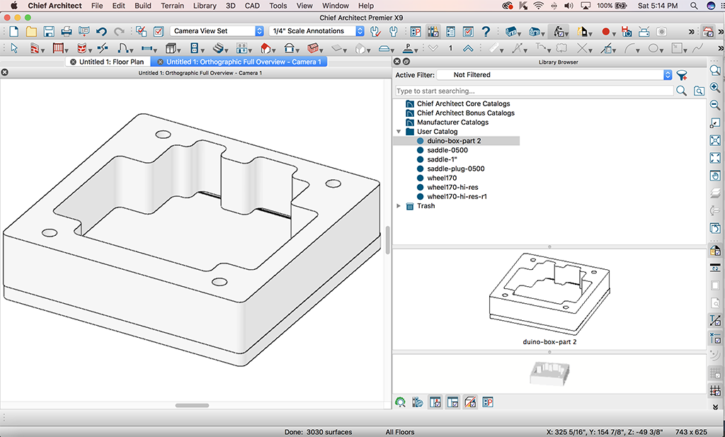
First, I start with the design I developed during Week3: Computer-Aided Design http://fab.academany.org/2018/labs/fablablccc/students/paul-oneill/week03/week3.html. I did this by by measuring a typical 4" junction box, drawing out the box, and then designing my part as well as it's mirror image mate. I accomplished this with Chief Architect, a software package I use frequently when I am restoring hand-hewed antique barn timberframes.
I used a series of "construction lines" during the design process to translate dimensions of an existing part, over to my new design. I continue checking the design by progressively copying the part and adding features. I render a pan view, an elevation view, and an ortho view. I went further by extruding the polyline in the reverse direction of the part to make a mold. I would later find that this was not really necessary to do.
PLAN VIEW

ELEVATION VIEW

ORTHO VIEW

File: duino-box-Orthographic Full Overview Image.pdf
Now thatI had a model developed, I needed to cut it on a CNC. The ShopBot at LCCC wasin the process of being moved to an upgraded facility. I attempted to use the ShopBot at Case Western Reserve University's Think[Box], but the person who certifies makers was not available. I was fortunate to be able to make arrangements with my 2017 classmate, Corey Rice, to use the ShopBot at the makerspace at Mayfield High School, Mayfield, OH, where he is the resident makerspace supervisor as well as a full-time Physics and Engineering teacher. My first attempt would to be making a mold out of 2" thick closed-cell XPS (eXtruded PolyStyrene) board.

Corey suggested I try taping it down with duct tape. I tried, but I felt the board was not secured sufficiently, and might come loose during cutting. I added two wood screws to fix the foam to the platen.

Next, I decided to use a 1/2" center cut upcut end mill. Just so happens that the 1/2" cutter was already in the machine, so I was good to go. I did not have to install the end millintothe ER32 TG collet. I am pretty familiar with endmills and collets from working for many years in a CNC machine shop. I next adjust the "tool height" with the ShopBot software over the foam and set the Z-datum. Next, we mill out the die.
 /
/
The small circular details were miscut by the Shopbot. Countours were miscut as well during the finish pass. During the rough pass, the contours seemed fine. The finish pass ruined the piece. It overcut the contour when it tried to mill the 1/2" diameter islands, and it left a channel in the floor of the mold.
I revised the design and eliminated the 1/2" diameter islands and cut just the rough pass. The mold came out fine.
Next, I had some Smooth-On material on hand. I use Smooth-On to make stamping tools for vertical carved concrete tool making. The material which I had on hand is called Smooth-On Vytaflex-20. This material is a urethane rubber. Product summary for this material can be found here: https://www.smooth-on.com/products/vytaflex-20/. The "Technical Bulletin" for this material can be found here: https://www.smooth-on.com/tb/files/Vytaflex_Series_TB.pdf . After I had my mold machined, I covered it with Smooth-On One Step Sealer and Release Agent. Product overview can be found here: https://www.smooth-on.com/products/one-step/ and the Technical Bulletin can be found here: https://www.smooth-on.com/msds/files/One_Step.pdf. The sealer is non-VOC and requires hand and eye protection, and is applied by brushing on a thin coat. Respirator is not needed in well ventilated area. The urethane rubber procedure:
POURING, CURING & PERFORMANCE...
The following recommendations were found on the data sheet. Since my classmate Corey Rice did not have any experience, nor any material to work with, and since the Fab Lab at LCCC was in the middle of being moved, I decided to make this a group effort. I did extend the offer to my other classmate, Martins Krebs. Martins said he had material and was all set. I went over the following procedure with Corey:
For best results, pour your mixture in a single spot at the lowest point of the containment field. Let the rubber seek its level up and over the model. A uniform flow will help minimize entrapped air.The liquid rubber should level off at least 1/2” (1.3 cm) over the highest point of the model surface. Curing - Allow rubber to cure a minimum of 16 – 24 hours at room temperature (73°F/23°C) before demolding. VytaFlex® 10 should cure for at least 24 hours before demolding. Cure time can be reduced with mild heat or by adding Smooth-On “KickIt®” Cure Accelerator. Do not cure rubber where temperature is less than 65°F/18°C. Post Curing - Optional . . . Following an overnight cure, heating the rubber to 150°F (65°C) for 4 to 8 hours will increase physical properties and performance. Using The Mold - If using as a mold material, a release agent should be applied to the mold before each casting. In & Out® II Concrete Release Concentrate (available from Smooth-On) is recommended for releasing concrete. Performance & Storage - Fully cured rubber is tough, durable and will perform if properly used and stored. The physical life of the rubber depends on how you use it.
Corey mixed the material and did the pouring. Since I have done this before, I observed.


We mixed one batch. My mold is on the left. Corey's mold is on the right. Gloves and safety glasses a must.

We experimented with wrapping the mold with plastic wrap. It made the backside of the casting rough. However, this was not going to impact the performance of the casting. After curing for 24 hours at 70 degrees F, apply 150 degree F heat for 16 hours in my AGA cooker to allow the polymer to vulcanize, or cure well. There were some bubbles in the material, but not on the side of interest.


After curing, I crack the foam in half to release the part. Remove the part from the foam.

(id='problems')
The part looks fine, but it is a replica of the part. This would be more useful if it was a replica of a mold which Hydrostone could be poured into. I made a plug of the part instead of a mold of the part.
Next, I 3D print the part with all the details so I can study my next attempt at a mold, and help me get things straight in my mind!

After I worked out my design by 3D printing, I made a rubber mold, first by making a mold of the mold in machinable wax.
(id='molding')

This part was machined on the Forest Scientific Router. Took about 3 hours of runtime. I used a 1/2" upcut mill, 12,000 rpm, 100 ipm. The nice thing about the Forest Scientific, besides that it is an accurate closed-loop CNC, is that you can override spindle speed and feedrate from the console, and the E-Stop stops the spindle. I ended up needing a deep groove around the designed part. I channel cut the groove 1/2" wide in three passes of 0.625" deep. The milling cutter was recutting it's own swarf on the perimiter of the mold and made a sticky mess. I had to use a scraper to clean out this deep groove. Next time, I will use the same cutter, but a bigger piece of machinable wax and a groove which is wider than the cutter. I did manage to clean it out with a paint scraper. I also used the paint scraper to put a very small chamfer on all the sharp corners of the wax.
.
I next poured the rubber into the plastic mold using the previous procedure. The part released from the wax with a little difficulty. Since the part is rubber, I was able to gently stretch it out of the wax mold. The result was a mold for making a part in Hydrostone. The sidewalls were a little flimsy, so I added wood supports.
Hydrostone is a fairly safe material. Nevertheless, the manufacturer requires you to wear a NIOSH approved respirator and gloves. The data sheet for Hydrostone can be found here:
Mixing instructions from the Hydrostone data sheet are found below. Hydrostone dictates you weigh both the material and the water in the following ratio: 32 lbs. water/100 lbs. product (15 kg water/45 kg product). Neil Gershenfeld notes that your mix should look something like pancake mix. When I weighed the mix, it did indeed come close to the consistancy of pancake mix.
- Use potable water at temperatures between 70 °F (21 °C) and 100 °F (38 °C). Because variations in slurry (USG Hydro-Stone Gypsum Cement and water mixture) temperature produce variations in set time, it is important to keep both the USG Hydro-Stone Gypsum Cement and water in a stable temperature environment prior to use. The higher the temperature of the slurry, the shorter the set time. Conversely, the lower the temperature of the slurry, the longer the set time.
- Weigh both the USG Hydro-Stone Gypsum Cement and the water prior to use for each mix. The water-to-USG Hydro-Stone Gypsum Cement ratio is critical because it governs the strength and the density of the final cast.
- Sift or strew USG Hydro-Stone Gypsum Cement into the water slowly and evenly. Do not drop large amounts of USG Hydro-Stone Gypsum Cement directly into the water as proper soaking of the USG Hydro-Stone Gypsum Cement may not occur. USG Hydro-Stone Gypsum Cement should be fully dispersed in the water prior to mixing. Small batches require less soaking time than large batches. See USG IG503 Plaster Mixing Procedures for specific soaking instructions.
- Mixing USG Hydro-Stone Gypsum Cement slurry is one of the most important steps in producing USG Hydro-Stone Gypsum Cement casts with maximum strength, absorption, hardness and other important properties.
- Mechanically mixed slurries develop uniform casts with optimal strengths. USG Hydro-Stone Gypsum Cement can be mechanically mixed through both batch and continuous processes. Proper blade and bucket dimensions are important for obtaining the best batch mix (see USG IG503 Plaster Mixing Procedures for details).
- Longer mixing times result in higher mold strength and shorter set times.

Directions call for mixing water to material by weight. 32 lbs. water/100 lbs. product (15 kg water/45 kg product) Put material on scale and figure correct amount of water.
Shore up flimsy walls of mold with wood. The "rubber" urethane has very litle firmness.

Pour in the hydrostone material.

Let the hydrostone seek level. Te pour surface does not need to be extremely flat ion this application.

After material hardens (overnight), release the wood supports.

Remove the mold from the wood base.
(id='heroshot')

Release mold and inspect resulting part.
(id='heroshot')

Commercial Arduino board fits in case.

Case fits on top of standard PVC junction box.
(id='files')
(File: duino-box-part.gcode.zip)
(File: duino-box-part.plan.zip)