Design and 3D print an object (small, few cm) that could not be made subtractively
3D scan an object (and optionally print it)
Learning outcomes:
Identify the advantages and limitations of 3D printing and scanning technology
Apply design methods and production processes to show your understanding.
Have you:
Described what you learned by testing the 3D printers.
Shown how you designed and made your object and explained why it could not be made subtractively.
Scanned an object.
Outlined problems and how you fixed them.
Include your design files and ‘hero shot’ photos of the scan and the final object.
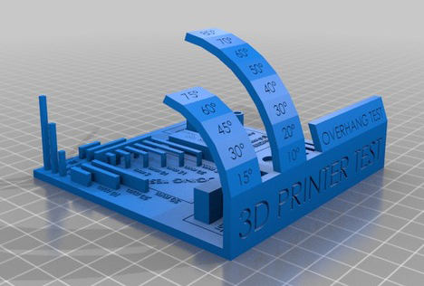
Test the Design Rules for your printer
The first test I did for the 3D printer was from a design found on Thingiverse. It is a very comprehensive test that will put your printer throught the works. If it needs adjustments or recalibrating, this test will show you.
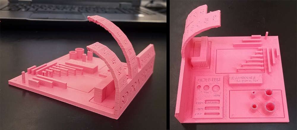
Here is the result of it printing on our Makergear M2; Looks pretty good! Only thing really lacking is a lot of the recessed text is lost.
---
extruder temp: 220C
build plate temp: 60C
infill: 50%
raft: no
support: no
layer height: 0.3mm
print speed: 30m/s
cooling fan speed: 100%
filament size: 1.75mm
---
3D Design
Programs I use:
Rhino
Solidworks
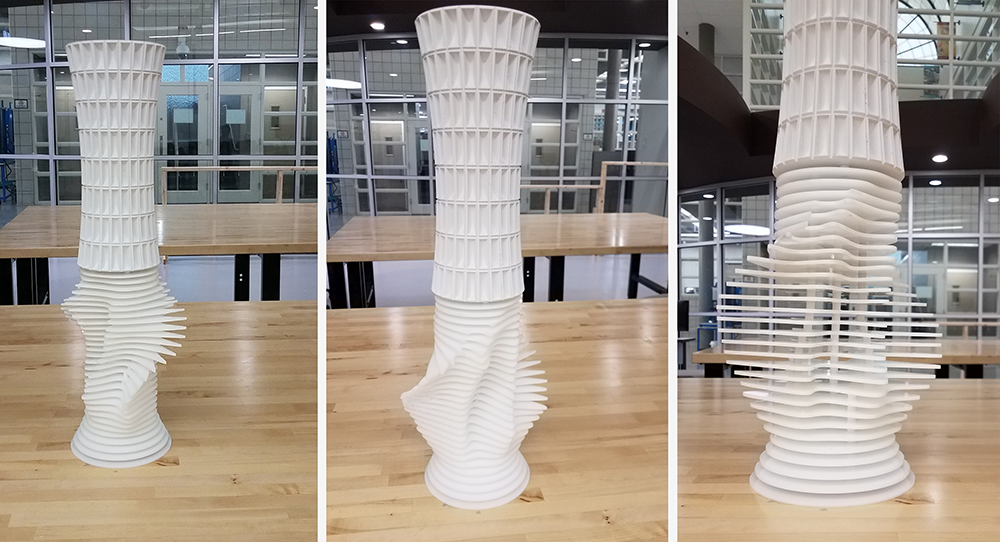
One of the few things in this course I am already somewhat competent at, for 3D designing I primarily use Rhino and Solidworks. This week, I want to make a type of 'trophy-like vase' with both 3D printed and laser cut components. This project is perfect for all aspects of this week's assignment, and week 4's assignment. Hopefully it will look great when it's finished.
First, I started playing with some vase-forms, and then began narrowing down which ones I liked.
After I narrowed a few down, I begoan work on a pattern for the exterior of the vase-form. I like to take a break from working on the same object for an extended period to give myself sometime to think of other things and come back to it with a refreshed mind
Once I finished coming up with a shape, using the Array transformation, I aArrayed it linearly to form a row of about 50 'cells'. Once that row was formed, I arrayed the row linearly down to make a sheet 8 rows deep. Once I had my surface made, I used a 'Boolean Union' command to join all the pieces into one closed polysurface. From here, I can manipulate the surface as I like, and will wrap the vase-form with it. To do this, I will use the 'Flow Along Surface' Transformation
This is after I trimmed off the extra cells that overlapped on the cell sheet I prepared, and I scaled the vase-form so that the cell sheet ends meet perfectly and the pattern appears to be seamless.
Finished Print: Printed on the Fortus 400mc
Now, I start mapping out the base layers I will cut out of acrylic on the laser. I want to get an idea of how the whole thing will look together, so I draw one shape and copy it multiple times, altering it slightly each time, and then organize them all in a stack.
Placed the vase component on top of the stack to see what it might look like
I cut out the bottom layers in 3mm acrylic, and started thinking about how I am going to assemble these layers. I decided I liked the spacing and the height it gives to the piece, so I designed a 7mm tall cylinder and printed out about 50 of them to use as spacers between each acrylic piece.
It came out pretty good, but needs something else to tie the 2 parts of the piece together. I will print out a wider ring for the bottom of the base with the same surface feature as the top vase part as see how that looks.
3D Scan + Print
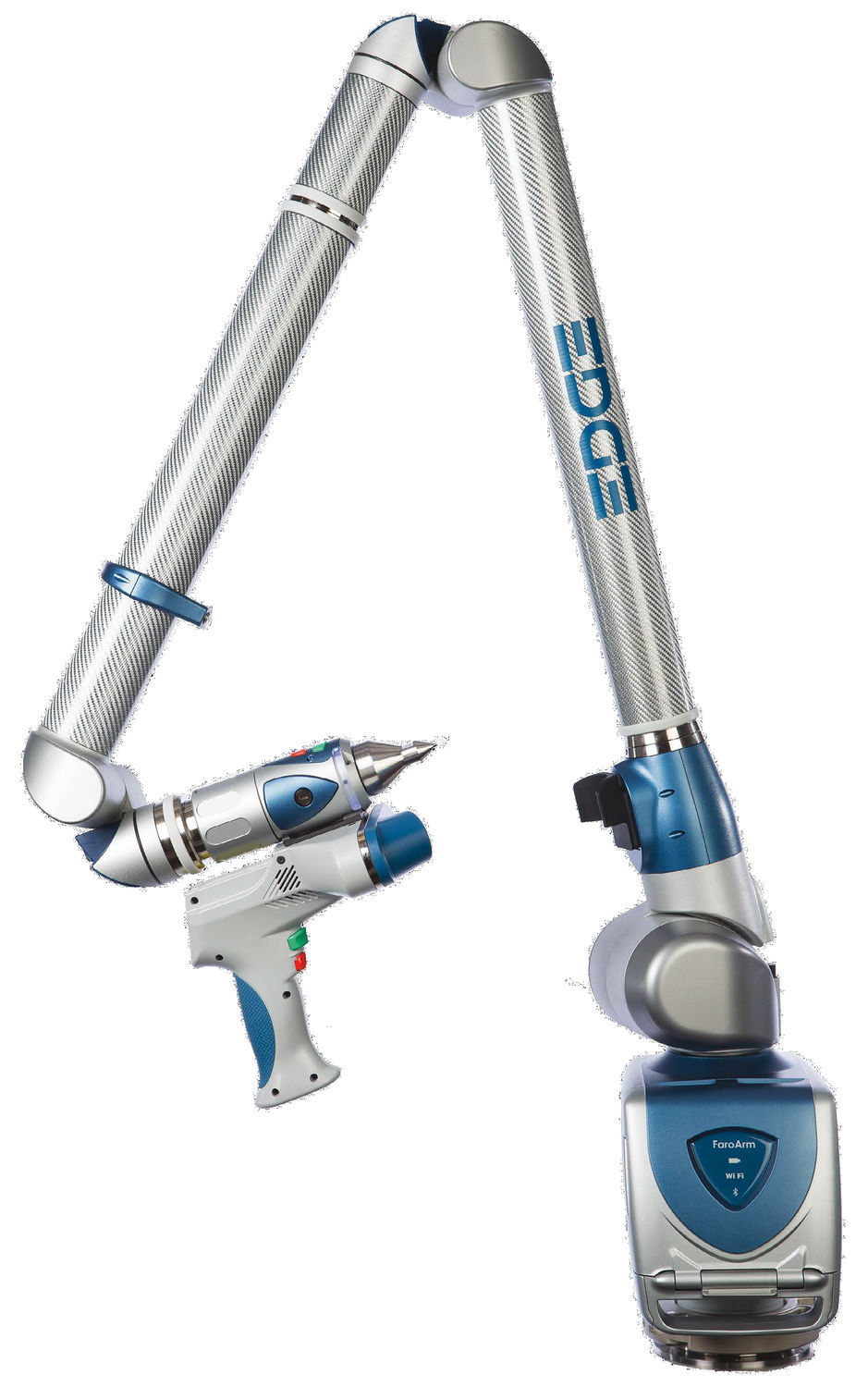
I decided to challenge myself with this part of the assignment. In my lab, we have a FARO Arm: Edge portale 3D measuring arm.
It has laser scanner, and a touch probe scanner in the same assembly. I primarily use the laser, because the resolution of the laser is incredible; better than any other scanner I have seen.
In conjunction with Geomagic Design X, I can laser scan an object with multiple sweeps, and DesignX will align them and stich them together in real time as I'm scanning. With these powerful tools at my disposal, I chose a difficult object to scan and try to replicate.
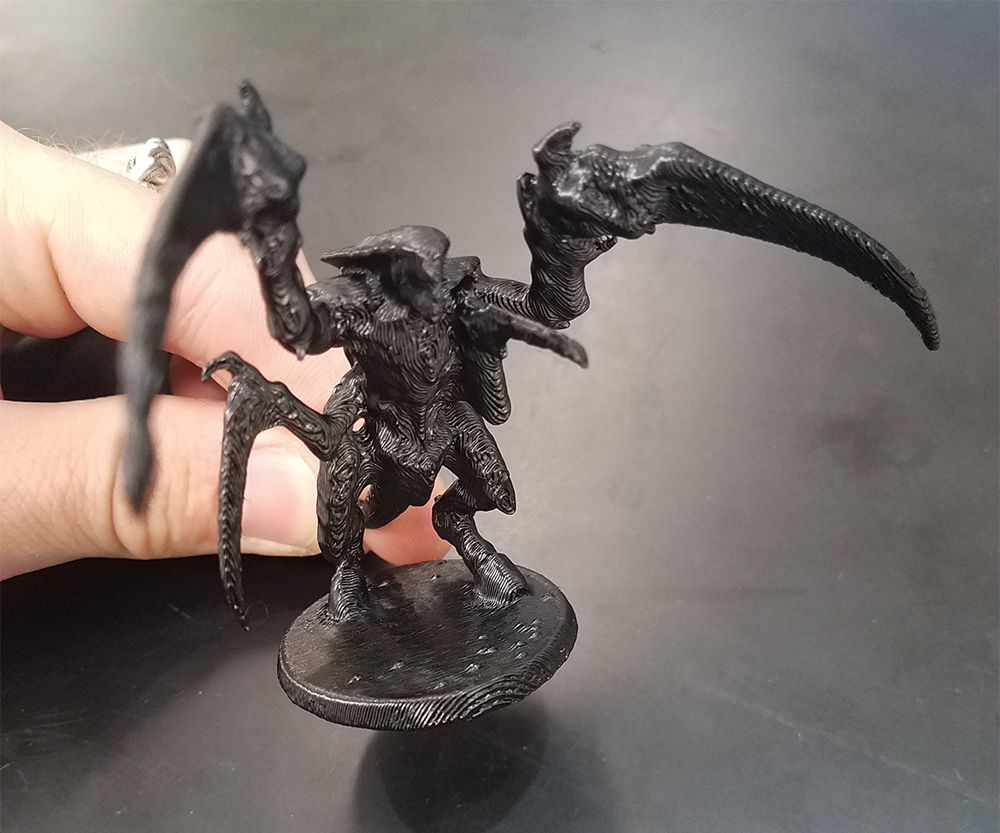
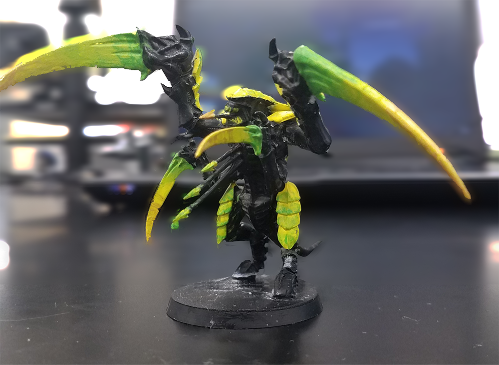
My Object
I found a little tyranid figurine of mine from back in the day. Time t test my scanning skills.
Booting up DesignX, open up the Home tab. LiveScan(TM) is the tool we use to access the FaroArm and scan into the program.
Once LiveScan(TM) is opened up, make sure the FaroArm is the selected Device and connect.
If you need to calibrate, go throught the walkthrough to calibrate the laser. Once calibrated, hit the Play button, and the laser scanner will turn on. Press the green trigger to start the scanning; Press it again to end the scan. You can do this as many times as you need to move around the object, fill in holes, and reduce noise. Geomagic will do a relatve stiching of each scan reletive to each other in space.
DO NOT MOVE YOUR OBJECT ONCE YOU START SCANNING
Once you finished scanning, I always go throught the mesh wizard. It cleans up all the noise, allows you to remove unwanted objects (like the clip holding the figurine), and patch all holes to make a water-tight mesh.
I exported the scan as a high resolution .STL. I need to print this in the most accurate and high resolution printer we have access to. For me, the best option that is up and running for me right now is our Fortus 400mc. The Fortus system uses Insight to slice objects and create toolpaths. I imported my .STL and oriented the object to minimize the amount of support needed.
Once sliced, you need to import the newly created .CMB file (made from Insight) into the controls software for the Fortus, Control Center. In this program, you import and organize models on the build platform. Once all your models are placed and organized, It will show you how much material your job will use and how long the build will take.
Hit Build Job. Go to the printer, insert a build sheet onto the build platform, and start your build.
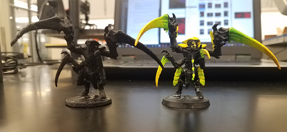
Once the print was finished, I threw it into the chemical bath to remove the soluble support. After a couple hours, i pulled out the finished model, rinsed it off with water, and this is the result:
Side by side of 3D scanned + Printed model and the original
.png)
.png)
.png)

.png)
.png)
%20(1).png)
%20(1).png)
%20(1).png)
%20(1).png)
%20(1).png)
%20(1).png)