Electronics design
This week assignment is to redraw hello-world board and add a button switch beside LED then we have to cut the board as per the the schematic diagram and solder the whole circuit parts.
Drawing hello-world Board
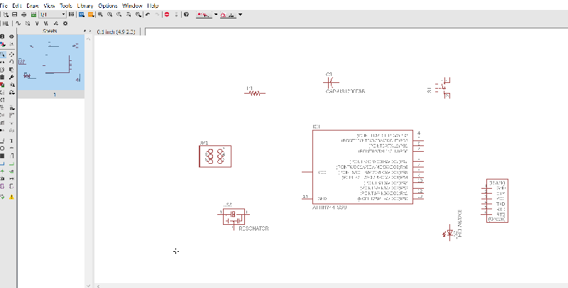
Initially i experimented with Eagle, Circuit maker and finally KiCad. Then i decided to go with Eagle since i findit is more intuitive Then i downloaded the specified component library fab.lib from the FabAcademy website added it to the library of the eagle.next step was to obtain the hello-world board from website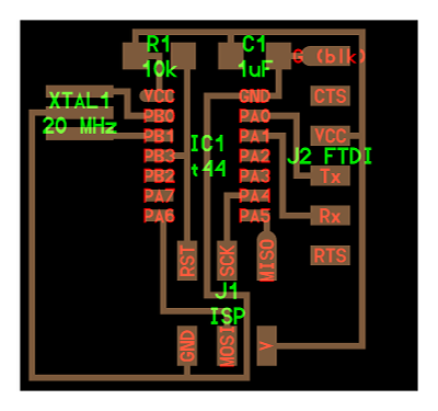
From the details obtained from sample image i began to draw the schematics using eagle software. Initially i placed the components from libarary to schematic area.
The components in the initial hello-world board are
- ATtiny44 x 1
- Resistor 499ohm x 1
- XTAL 20HZ x 1
- Resistor 10K x 2
- Capacitor 10uf x 1
- Push button x 1
- ISP header x 1
- FTDI header x1
- LED
final view schematic after the redrawing
Schematic_image

After Generating the schematic we can use generate option in eagle to obatin the board design. After Rearranging we will obtain the output as below
After auto-routing the board we will obatin below output
Board Generation

Trace_image

Cut_image

Output after soldering
