INPUT DEVICES
Assignment
- Measure something: add a sensor to a microcontroller board that you
have designed and read it.
-
Measure the analog levels and digital signals in an input device.
What I Did
- Designed a board with a Phototransistor in Eagle
-
Milled and soldered the components
- Programmed the board
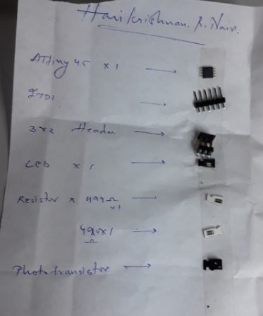
Input devices available in fablab
are PIR, ultrasonic, hall effect sensor,
temperature sensor, light sensor and accelerometer.
I decided to try light sensor which is a photo transistor for this week's assignment.
Introduction
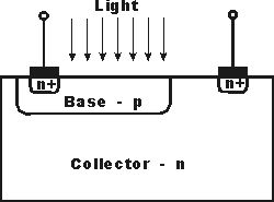
A phototransistor is a light-sensitive transistor. A common type of phototransistor, called a
photobipolar transistor, is in essence a bipolar transistor encased in a
transparent case so that light can reach the base–collector junction.
I made a board in which an LED is activated by the phototransistor. The values are set
in the programming for the LED to activate and deactivate.
The design was made using Eagle. Below is the schematic of the circuit
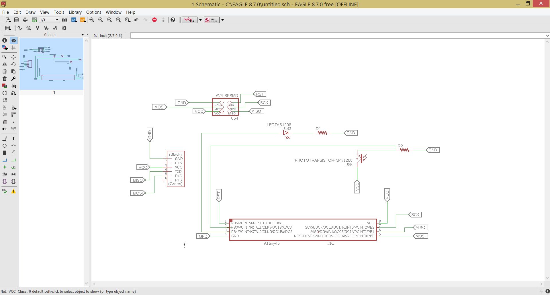
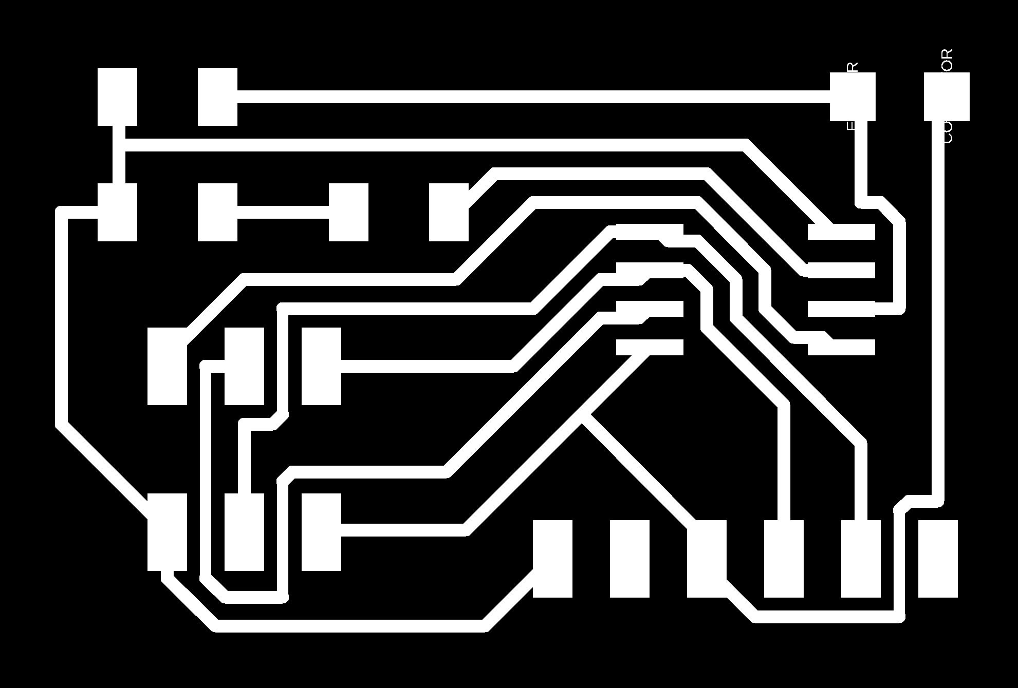
The image was exported as image file in monochrome.
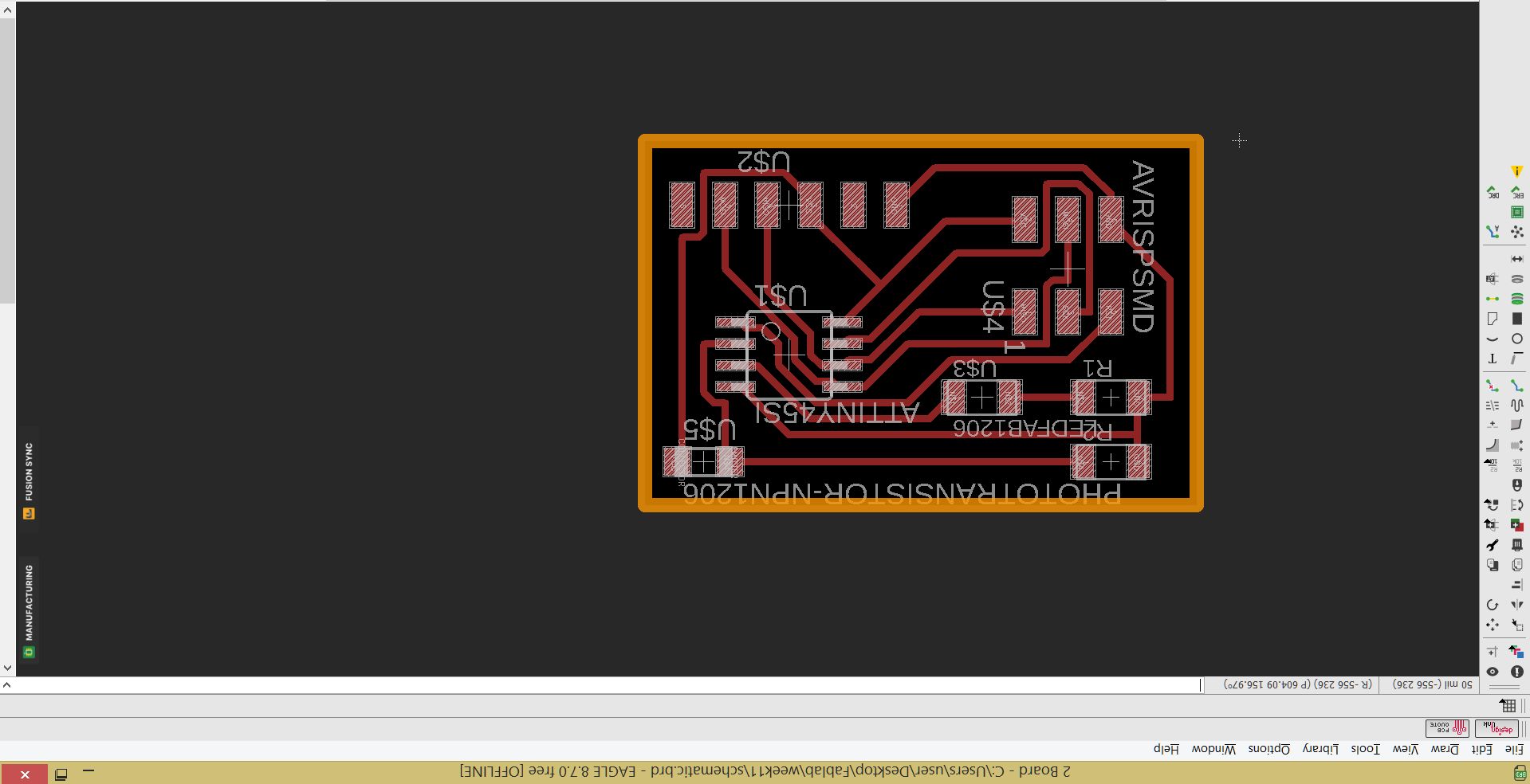
Milling
 cutting

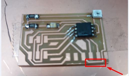
Final board
The components were soldered correctly
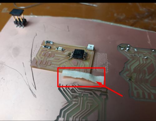
The FTDI cable had to be connected at the edge, but there was a connection
that had a chance to get shortcircuited near the edge. So I put a masking tape
over it before soldering the FTDI pins.
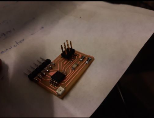
The Final Board
Programming the Board
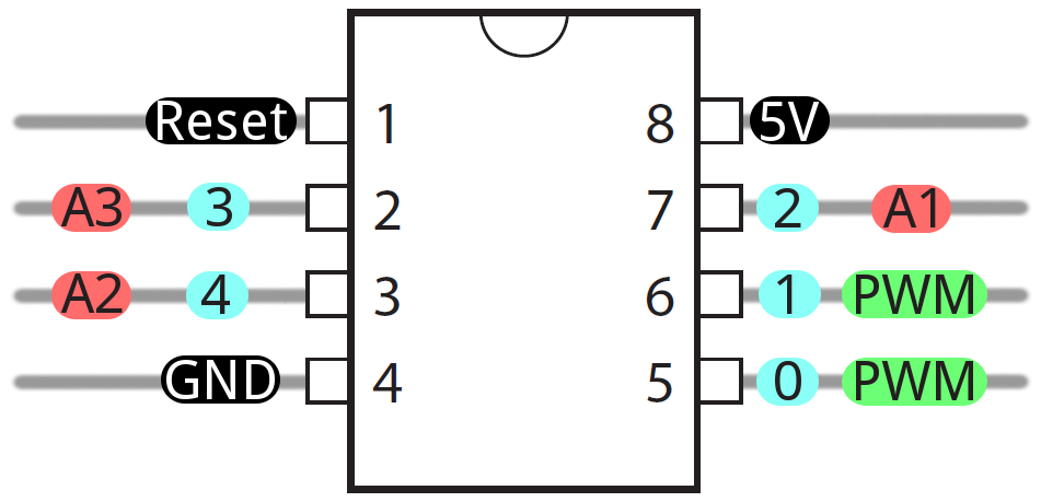
ATtiny45
I used ATtiny45 for this board. The pinout diagram is as below
I used Arduino to program the board. The pins were set and the programming was
was done as follows
Arduino Code
            #include<SoftwareSerial.h>
            SoftwareSerial window(0,1);// rx tx
            void setup(){
              window.begin(9600);
              pinMode (PB4,OUTPUT);

            }
             void loop()
             {
              int light= analogRead(A3);

              window.println(light);

              if(light <=400)

              {
                digitalWrite(PB4,LOW);

              }
            else
            {
              digitalWrite(PB4, HIGH);
            }
            }
Final Output
The programming was successful. The phototransistor was working perfectly.
The output values were showing on the laptop screen. It was programmed to
light up the LED for all values above 400 and the LED remains off for all
values below 400.
Download files here
Board
schematic