Group Assignment:
- design a machine that includes mechanism+actuation+automation
- build the mechanical parts and operate it manually
- document the group project and your individual contribution
Robotic Arm with 7 Servos
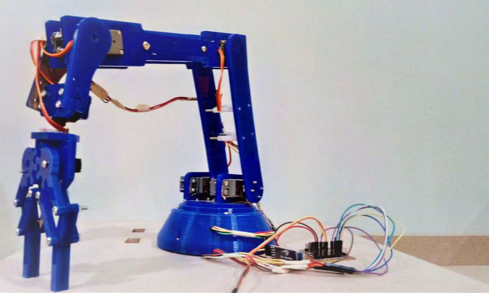
Robotic arm with 7 Servos
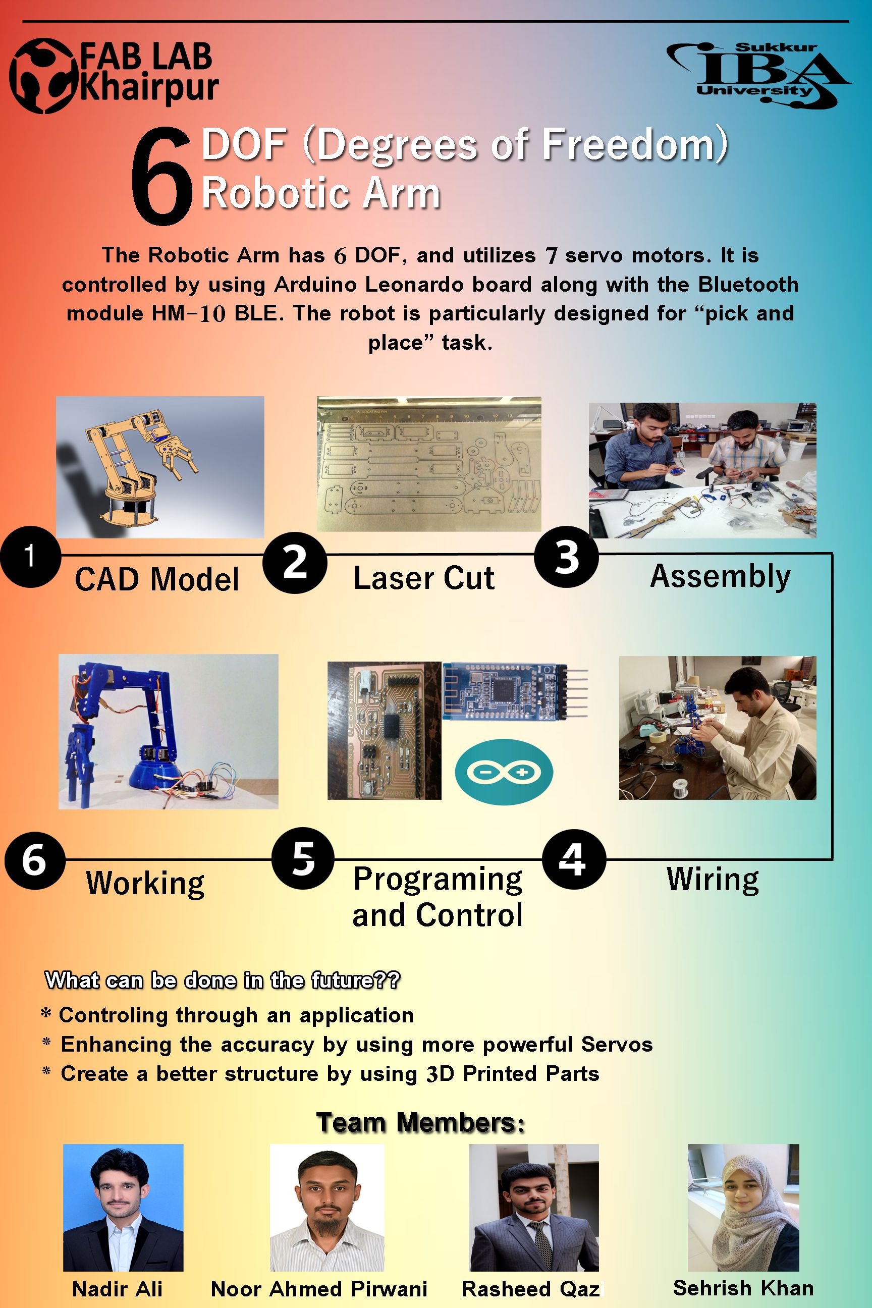
Poster Describing the Workflow of the Assignment
The demonstration of working of Robotic arm is shown in the video below. It's the first time that we have completed our assignment before the deadline ;)
In this week and the upcoming week, we have to make a Machine.So, first we need to design the mechanical parts of our machine in this week.It is basically a group assignment, and every person is required to do a part of assignment and document their contribution.
Introduction:
In all essential aspects a robotic arm resembles perfectly the human arm in appearance,structure and in many of its functions.A human arm can move freely in 7 axis, but now a days it's not a big deal to see robotic arms which have the same degrees of freedom. A typical robotic arm is made up of seven metal segments, joined by six joints. The computer controls the robot by rotating individual step motors connected to each joint (some larger arms use hydraulics or pneumatics) Your arm's job is to move your hand from place to place. Similarly, the robotic arm's job is to move an end effector from place to place. Designed and realized in the project, the robot arm has the ability to move in 5 axis directions with 7 servo motors.
Benefits of Robotic Arm
- Robotic arms are fast and perform the pick and place tasks accuratel
- Robotic arms save the human labor time, and reduces the risk of injuries associated with tasks like replaceing,moving,picking and placing etc.
- Depending on the desired tasks that you want to do from your robotic arm, the accuracy can be increased.
- Robot arms work in agriculture, aviation, postal services, recording studios, and a thousand other applications
- Robotic arms render ease of use, better range of mobility, and re-programmability to increase the accuracy of tasks.
Axes of Robotic Arm
The Robotic arm moves in three axes:
- X-axis defines horizontal motion.
- Y-axis defines vertical motion.
- Z-axis defines depth motion.
The working of the robotic arm in each individual axes can be understood in a better manner by resembling and anlaysing the movement of a human arm.Each axes charecterize a space through which the robotic arm moves.If we associate the use of axes as a pivot point , then each pivot point is responsible for motion of the robotic arm for a range of motion in the same manner as our wrist and elbow. Increasing the number of axes or pivots , increases the overall range of motion. Here, we will be using 5-axes motion and for that we need 7 servo motors.
Different Parts of a Robotic Arm:
- Controller
- Manipulator
- Gripper or end effector
- Power supply or energy source, and
- Data acquisition system (vision sensors system).
- Programming
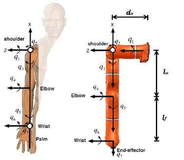
Kinematics of the Robotic Arm
The human arm consists of two distinct parts: the wrist with three minor joints, and the arm’s two major joints, i.e., the shoulder and the elbow. The function of the human wrist is to provide the orientation of the object held by the hand. Various functions of the arm may be explained as follows:
similarities between a human arm and a Robotic arm
>> Hold your right arm and hand straight out. Keeping the palm in downward direction, this is the reference angular position (0o). Then rotate your wrist as far in both clockwise and anticlockwise directions. This is called roll motion and limits of rotation as -180o and +90o respectively, i.e., Roll (angle) = 180o – 0o – (-90) = 270o.
>> Hold your right arm and hand straight out. Keeping the palm in downward direction, this is the reference angular position (0o). Then rotate your wrist as far in both clockwise and anticlockwise directions. This is called roll motion and limits of rotation as -180o and +90o respectively, i.e., Roll (angle) = 180o – 0o – (-90) = 270o.
>> Again holding the right arm in the reference position (0o) and without rolling the hand. Move the wrist from the initial straight position as far as possible in a downward and then in an upward direction. Called pitch motion and its limit positions are at – 90o and 50o, i.e., Pitch (angle) = 90o – 0o – (- 50) = 140o
>> Holding your right arm straight out and the wrist making neither a roll nor a pitch motion. Let the fingers point horizontally as far as possible to the right and then to the left. This is the yaw motion and its limit positions are at – 45o and + 15o, i.e., Yaw (angle) = + 45o – 0o – (- 15) = 60o
Defining the joints and DOF of the Robotic arm
Roll, pitch and yaw are considered independent motions and therefore referred to as degrees of freedom. The second part of the human arm has two major joints with three degrees of freedom, two in the shoulder and one in the elbow. But the robot has a shoulder with one degree of freedom only, and thus the robot waist is introduced as a substitute for one of the shoulder’s independent motions. In the case of a human the waist has a different function, i.e., it is for manoeuvrability by counter-balancing the human body against the gravitational load in changing body postures. The counter balance in robots is some time used by incorporating a mechanical loop in its structure.
The human arm has five fingers with three degrees of freedom in each one of them. These fingers are used to grip a part of any configuration either in conjunction of each other or individually independently depending on type of job, object to be handled and degrees of freedom to be used. The fingers are used independently with dexterity; contrary to this, the robot gripper has independent mobility and no dexterity except for very rare tasks. In 85% of pick-n-place industrial robots, the gripper does not have more than two or three fingers because in industrial work only the thumb, first and middle fingers are used. An important feature of the robot structure is the ratio of the length of upper arm to that of the fore arm, which is around 1.2. This implies that robot’s forearm should be either equal to or slightly shorter than the upper arm. If this rule is not followed there will be robot performance impairment. Remember, the robot is a mechanical system representing human arm, however, it cannot reach the human arm’s performance capabilities as this consists of large scale hierarchical system composed of large number of linear and non linear elements.
Task Division:
The whole project comprises of the following parts and divided in our Group. It's really an interesting and challenging task to do.
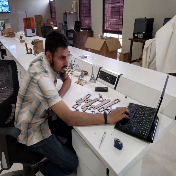
- CAD Design of the Robotic arm, Laser cut and 3D print the parts. (This Task has been Assigned to Mr. Noor Ahmed Raza Pirwani )
- Assembling the parts to make the Robotic arm (This task has been assigned to Ms. Sehrish Khan, Rasheed QAzi)
- Electronics Production , designing the Controller (This task has been assigned to Mr.Nadir Ali)
- Programming of the Controller(This task has been assigned to Noor Ahmed Pirwani and Rasheed Qazi)
CAD Design of the Robotic Arm:
The whole model was increased by 1/3rd of its original size. We are using 6mm blue acrylic for this project. Scaling factor is decided as 1/3rd because of hardware compatibility issues
Challenges faced while Scaling:
While scaling the Design , there were some limitations which were to be kept in mind. These are discussed below:
- As we are working in Solidworks, so we need to change the model part by part. Increasing the whole part size to 1/3 led to an increase in the dimension of screws' holes and the other internal shapes like motor placement, holes to fix motor shaft etc.
- We already designed and 3d print the base with respect to original size of robotic arm. Now to 3d print it again by scaling it
- is waste of material, so we were limited to keep the scale ratio of 1/3.
- The increasing in scale is also bounded to 1/3rd because an increase in the size any further will make the robotic arm be unable to handle the weight factor desired for the design.
- The size can be increased further if we manage to arrange high torque motors and make whole part again (with base part)
Resolving the issues of Scaling:
After analysing the design and hardware constraints, the following steps were taken to resolve the scaling issues: Instead of increasing the scaling factor of the whole part, first the internal parts designated for screws and size of other internal parts were decreased by dividing them with 1.33. After decreasing the internal parts by 1/3 , we increased the whole part to 1/3rd so that it can make screw holes, motor placement, shaft placement and other internal parts to there actual size.
The scaling process is illustrated by the pictures below:

1- these holes are used to 3mm we divide it to 1div3 to make it 2.25mm

2- the original model was on 3mm thickness so we change it to 4.5 which multiplied with our scaling factor to become 6mm

3- then we scale it to 1.33 percent of actual size, this step made thickness 6mm and made screwholes to again 3mm

4- screw holes are nearly 3mm as measured. other parts are also scaled it like this
There are other tools of solidworks used also while scaling like ; center line to check the boxes are alligned, mate tool for assembling the parts etc. Finally, the whole model was scaled up by the scale factor of 1/3, keeping the scale ratio constant.
LASER cutting of parts:
After scaling of all the parts in Solidworks, the parts were joined together and made an Assembly by creating the Mates as shown in the pictures above.The next step was to cut all the individual parts on Laser cut.Follwing are the necessary details of Laser cut of the parts.
- The .DXF files were imported in Inkscape to make a pdf file from the SVG.
- It was made sure that no space was left unused , so that we make the best utilization of the material
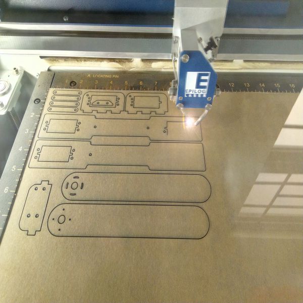
Laser cut doing the Job
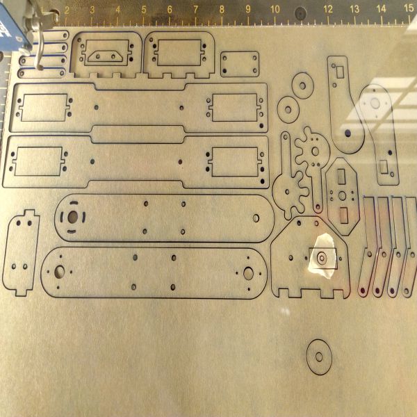
Laser cut Job is done , parts after Laser Cut
Assembling the parts of Robotic Arm:
Now, its time to assemble the parts to make the robotic arm with 6 dof. Following were the components required for assembling:
- --> Screws of 1 inch, 1.5 inch and 2 inch
- --> Nuts and Bolts
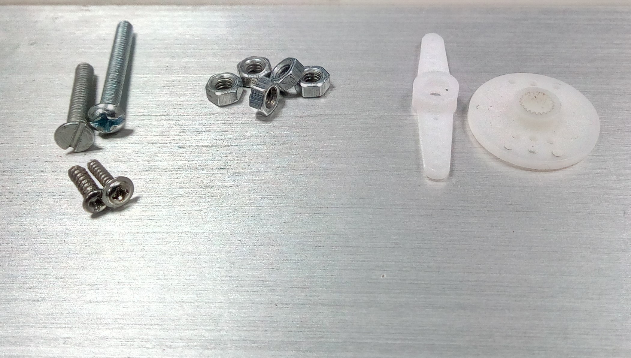
Components for joining parts
The parts are being assembled, as shown below:
Assembling the parts
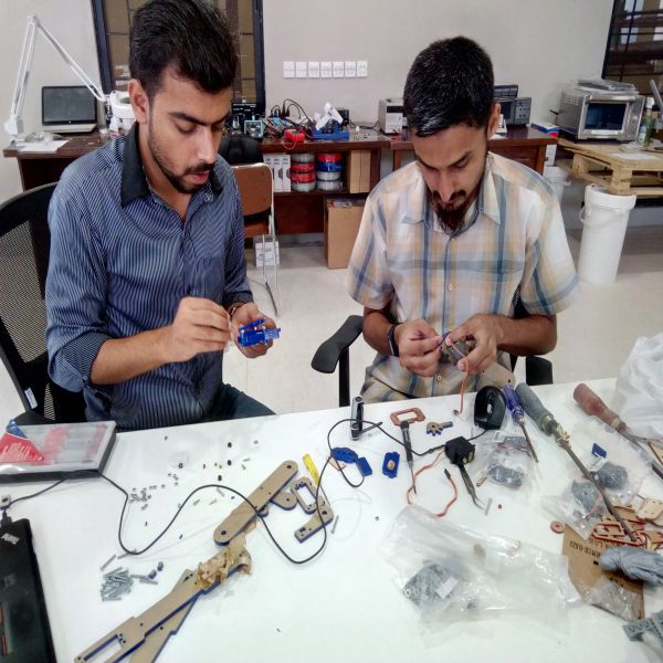
Assembling the parts
Issues faced while Assembling:
While Assembling the parts, the screws needed for connecting the servos to the acrylic sheet were small in width. This thing did not trouble us because its really not a big issue.
Resolved the issues of Assembling:
In order to fit the screws well and connect the servos, the holes were drilled a bit. Now, the servos fitted very well!
Wiring of the hardware components:
For testing purpose, we connected the wiring to each hardware component. All the VCCs and GNDs were made common.
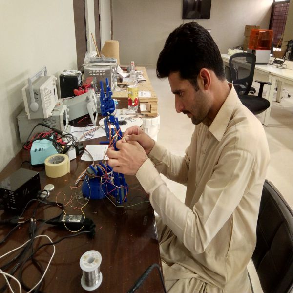
Wiring of robot
Controling the Servo Motors:
There are seven Steppers used in making the robotic Arm. The necessary details about each servo is given below:
- The 1st servo or the 1st degree of freedom is obtained through Hking HK15138 Aanalog Servo, is attached below the base, and it is able to rotate from 0 to 180 degrees. Its main function is the rotation of the whole robotic arm.
- The 2nd and 3rd servos combinely render the 2nd degree of freedom through Hking HK15138 Aanalog Servo and are attached at the shoulder joint . They rotate from 0 to 180 degrees. Their main function is to lift the robotic arm from ground to initial position that we have set.
- The 4th servo render the 3rd degree of freedom through Hking HK15138 Aanalog Servo and is attached at the Elbow joint . It rotates from 0 to 180 degrees. Its main function is to support the upper part or the end factor.
- The 5th servo is responsible for 4th degree of freedom is obtained through Hking HK15138 Aanalog Servo. It is attached at the wrist joint, and it is able to rotate from 0 to 180 degrees. Its responsible for the linear movement of wrist.
- The 6th servo is responsible for 5th degree of freedom, obtained through Corona CS-939MG Aanalog Servo. It is attached at the wrist joint, and it is able to rotate from 0 to 180 degrees. Its responsible for the angular movement of wrist.
- The 7th servo or the 6th degree of freedom is obtained through Corona CS-939MG Aanalog Servo, is attached at the gripper, and it is able to rotate from 0 to 180 degrees. Its main function is to pick and release the object. This is responsible for the movementof base.
The microcontroller used is Arduino Leonardo with (ATMEGA32U4 : 8-bit Microcontroller with 16/32K Bytes of ISP Flash and USB Controller).Arduino Leonardo is a customized version of Arduino, having 44 pins as shown below:
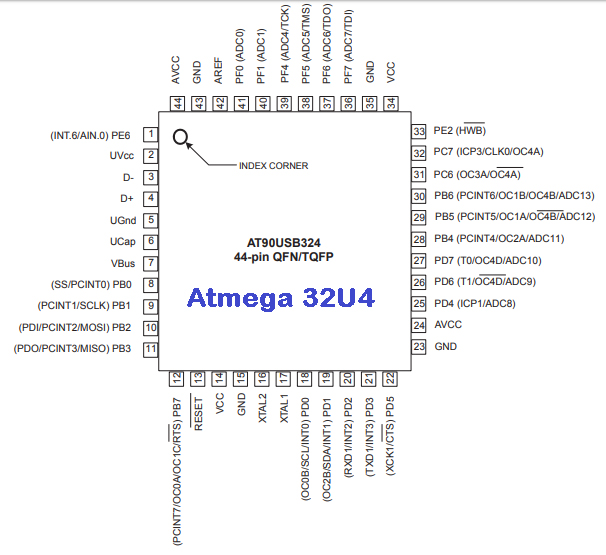
ATMEGA32U4 Microcontroller
The Leonardo gives almost the same functionality as Arduino UNO but Leonardo has an extra serial communication pins. Since we are not allowed to use commercialized boards , so one of our colleagues Mr.Nadir Ali had made his leonardo board in week 9. To read more about this board, the link of his version of leonardo is given HERE
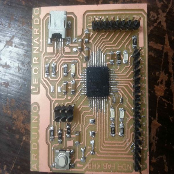
Arduino Leonardo Microcontroller
The whole functionality of the robotic arm is electrically manipulated using the Arduino Leonardo board. Following pins of Arduino Leonardo are used to connect and control the Servo motors and the Bluetooth module.
| Name of Motor / BT pin | Wire Color | Arduino Leonardo Pin |
|---|---|---|
| a | Brown | 3 |
| b | White | 5 |
| c | Orange | 13 |
| d | Yellow | 9 |
| e | Green | 6 |
| f | Dark Yellow | 10 |
| RX | Yellow | 0 |
| TX | Orange | 1 |
Table1 : Pin configuration for wiring and Programming
Programming :
The programming has been done in C language using the Arduino IDE. The bluetooth module(HM-10 BLE V 4.0) has been interfaced and Bluettoth Serial Terminal application has been used for giving the commands from the android phone. The arduino codes have been attached at the end of the documentation .
Working of Robotic Arm
Initially we were controling the robotic arm using the HM-10 BLE 4.0 Bluetooth module, for obtaining the values of servos to set the initial positions. Once we achieved the initial positions then we moved to programming it in a way so that it performs the task of pick and drop the object automatically. The video showing the working of robotic arm is attached at the top of page:
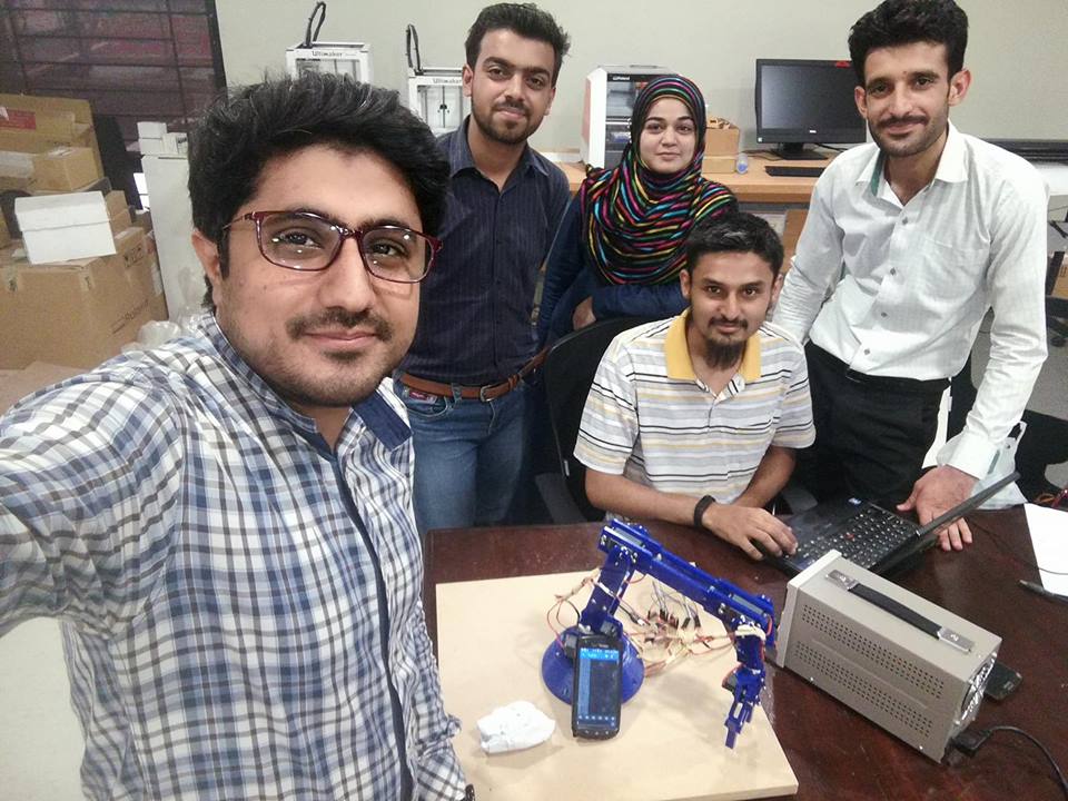
Group Picture with our Instructor Sir Sohail Ahmed Soomro after successful demonstration of project
Further Improvements:
Although the robotic arm works ery well but still it needs to be improved in following terms:
- Efficiency: The robotic arm performs the pick and drop , but it takes time.
- Application development:We are planning to develop pplication using MIT App Inventor.
- High Torque Servos:In order to increase the weight handling capability of the robotic arm , servos handling better torque can be incuded.
Conclusion:
This was our first group Project of Fab Academy, so it was a nice experience of collaborating together to make something. Moreover, we learnt about the working and controling a robotic arm; the basic factors like its kinematics, degrees of freedom, selection of hardware components like servos, and its limitations.