Today's Menu
Exercise 05 - 3D printing and scanning
3D printing
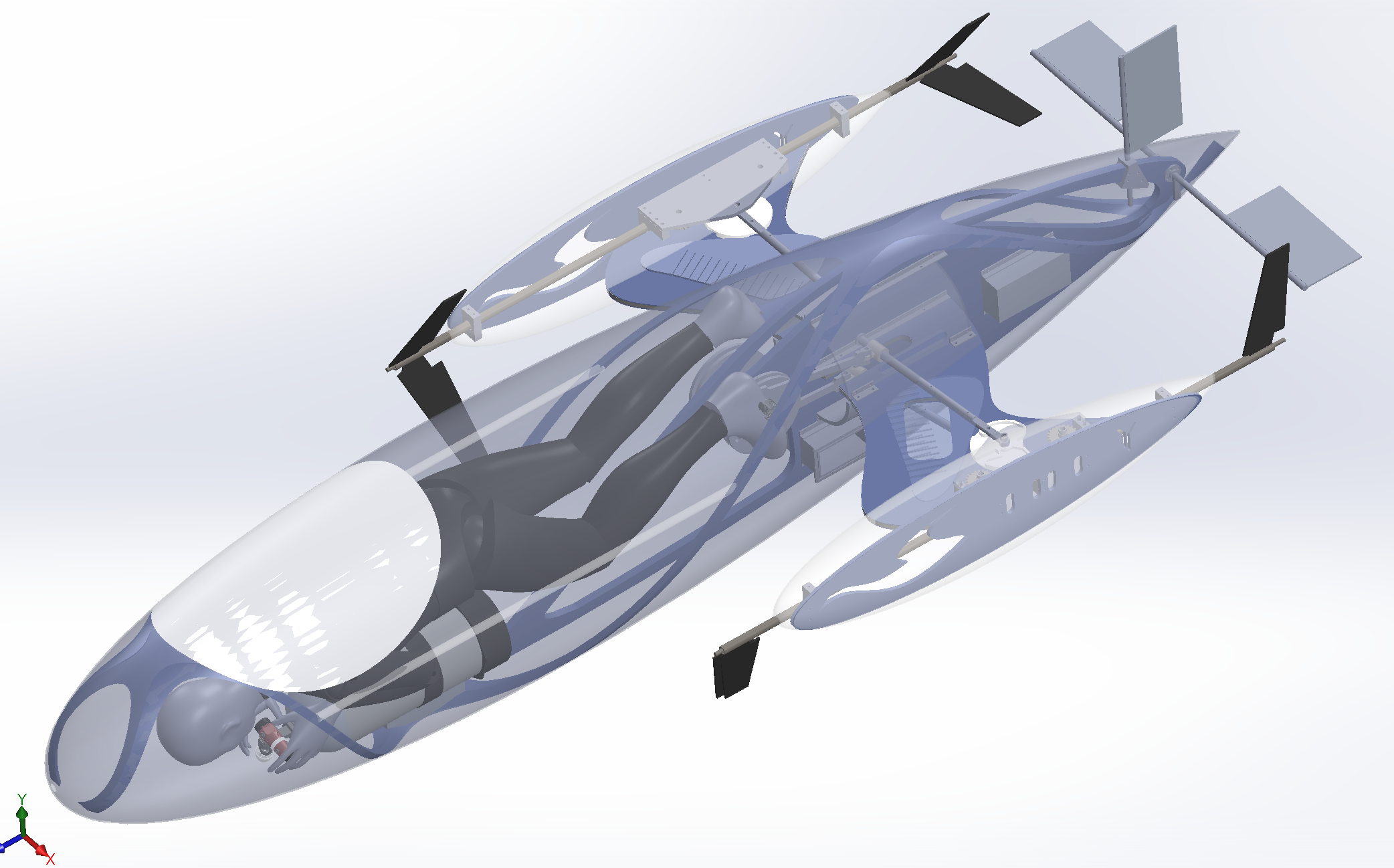
The first thing that came to mind when I started thinking about a complex model to print was the human-powered submarine I've been designing with my students these last few months. The outside of the submarine is a set of three rather boring cylindrical shapes, but the inside of the submarine is very nicely complicated, with a large number of small parts and long sweeping narrow-diameter pipes. Certainly not something I could just turn up on the lathe!
Conventional manufacture
An object as complex as this one could not be made all in one go with conventional subtractive manufacturing techniques. It would simply not be possible to get the head of a milling machine into the narrow volumes and to hollow out the various enclosed shapes. The object could be made (and indeed the final, full scale version will be) using conventional subtractive techniques to create the various parts, which would then be assembled in the manner of a model aeroplane. Even there, though, some of the parts will not lend themselves well to subtractive manufacturing, as they have overhangs and complex, narrow elements.
Prepping the model
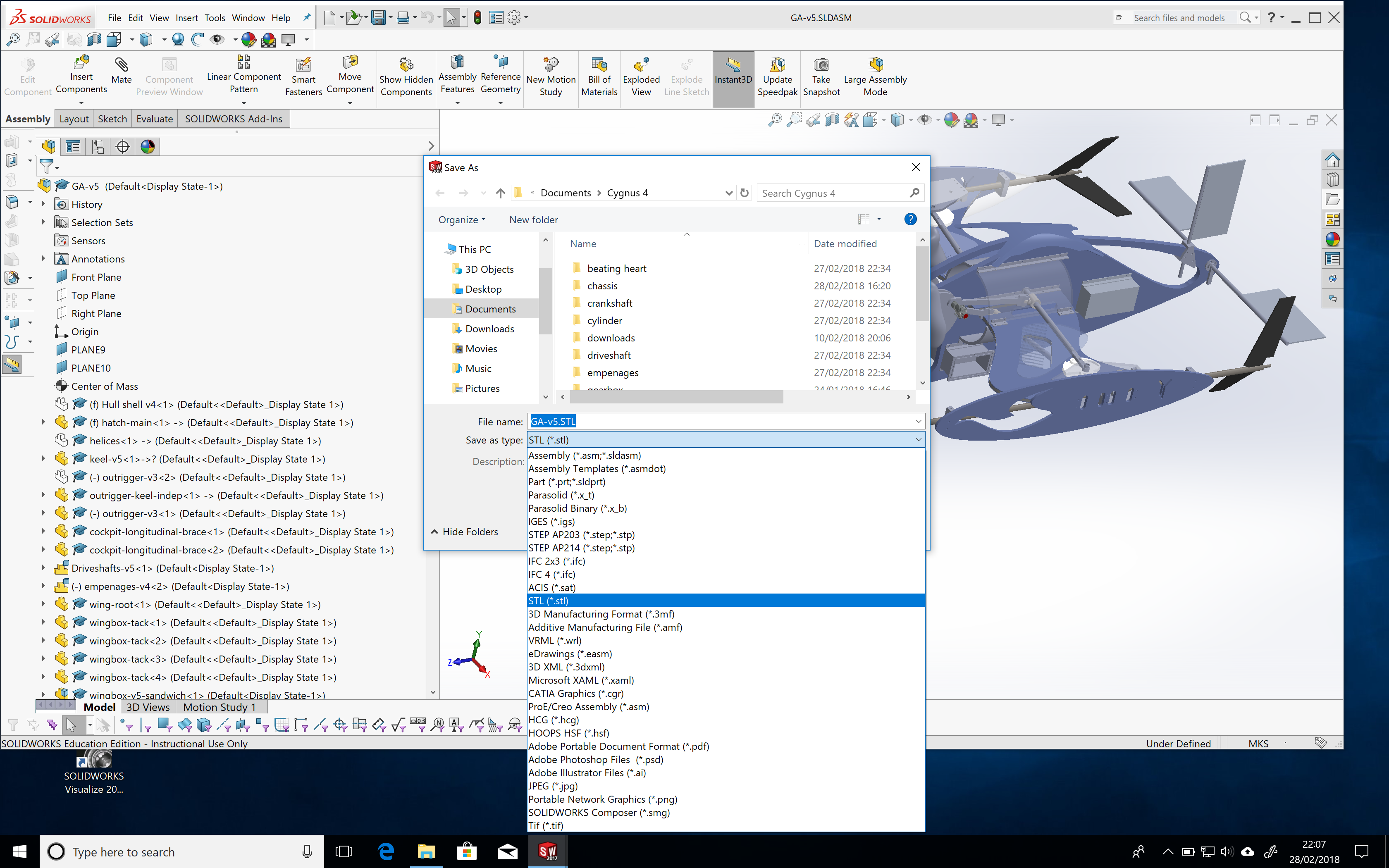
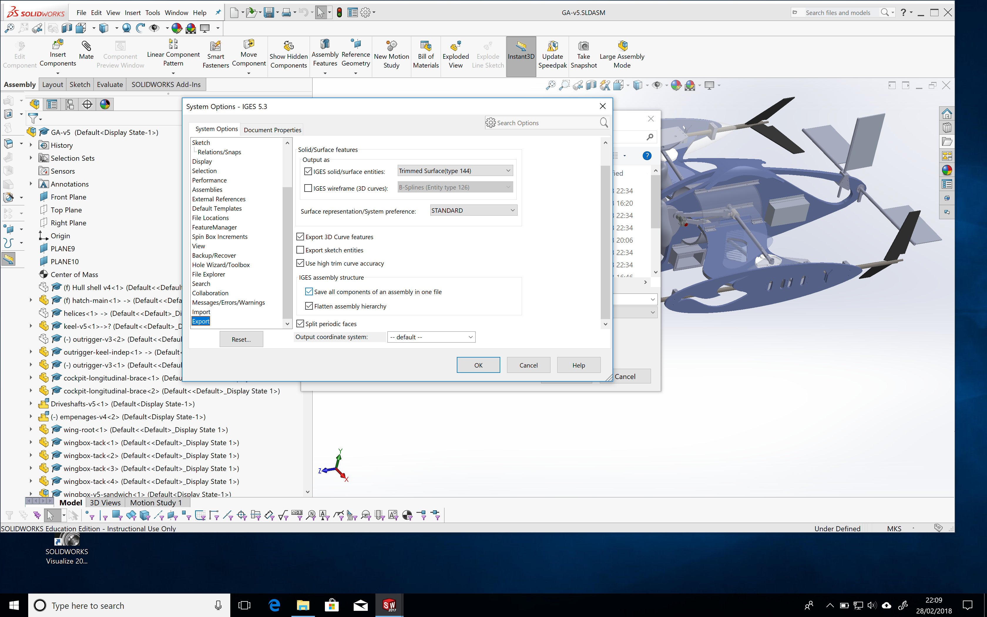
The first stage in preparing the model for 3D printing is to decide which elements of the assembly should be printed, then to make a single "part" out of the "assembly" in Solidworks. This is done by saving the assembly as an STL file (left hand screenshot below), and selecting the option to "save all components of an assembly in one file" (see arrow in right hand screenshot below).
 |
|
Next step is to put the model through a "slicer" to ready it for the 3D print job. The role of the slicer program is to prepare the CAM tracks for the head to follow as the extruded material is laid down. Ultimaker provides their Cura software for free download.
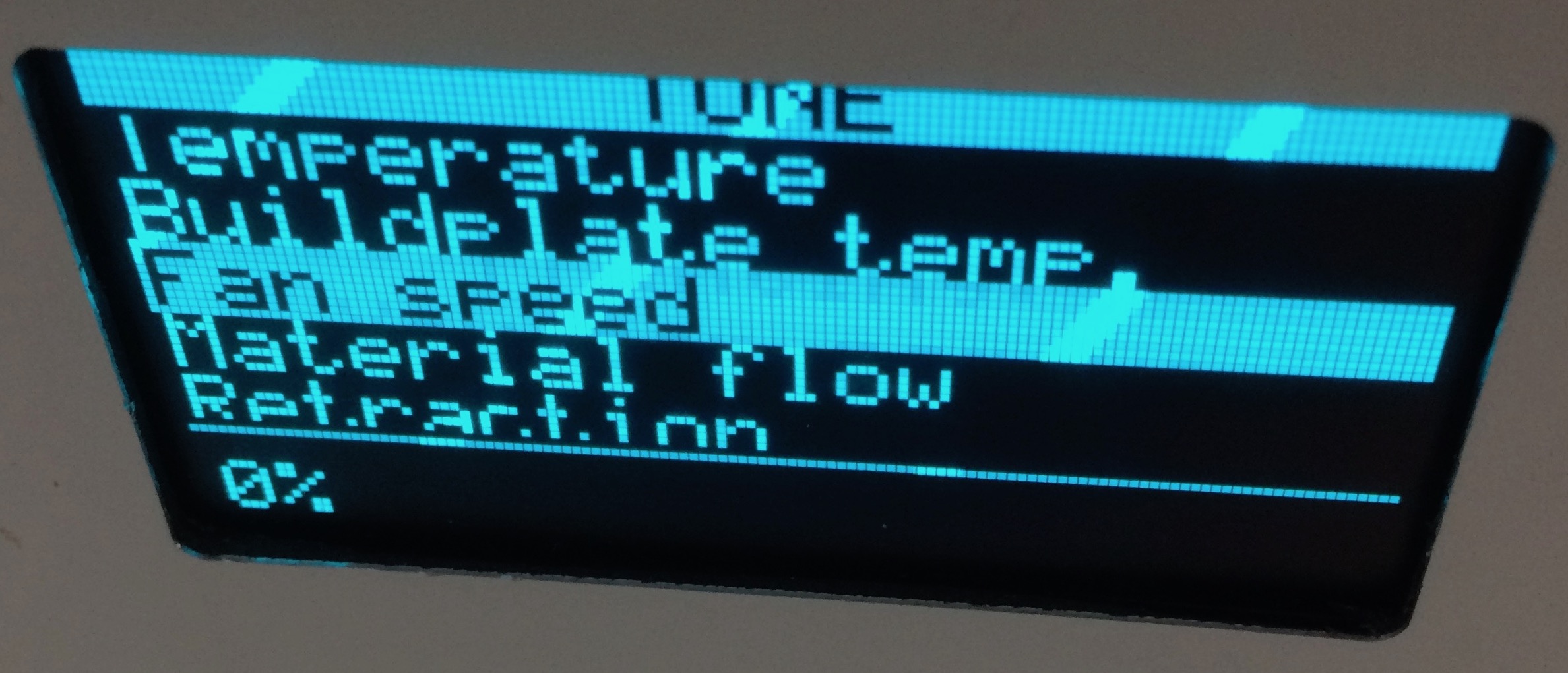
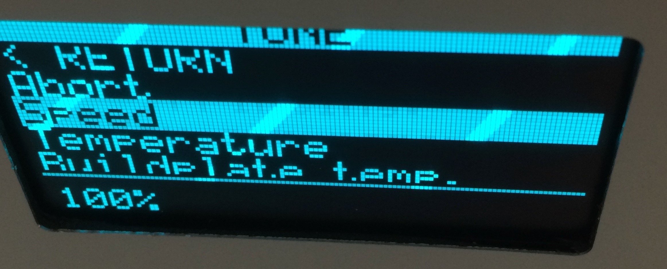
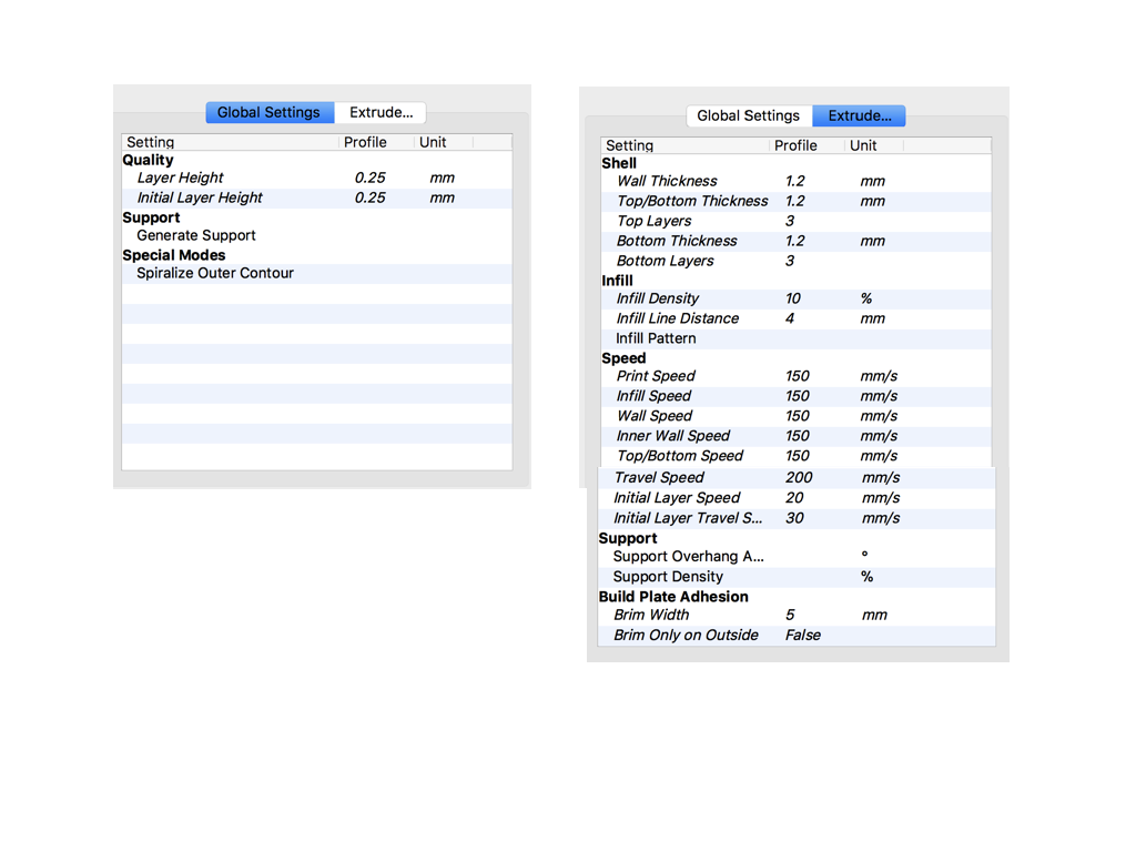
 | First settings. Something wasn't right with the text display in Cura. Zoom in to see the settings used. |
Lower precision printing - Ultimaker
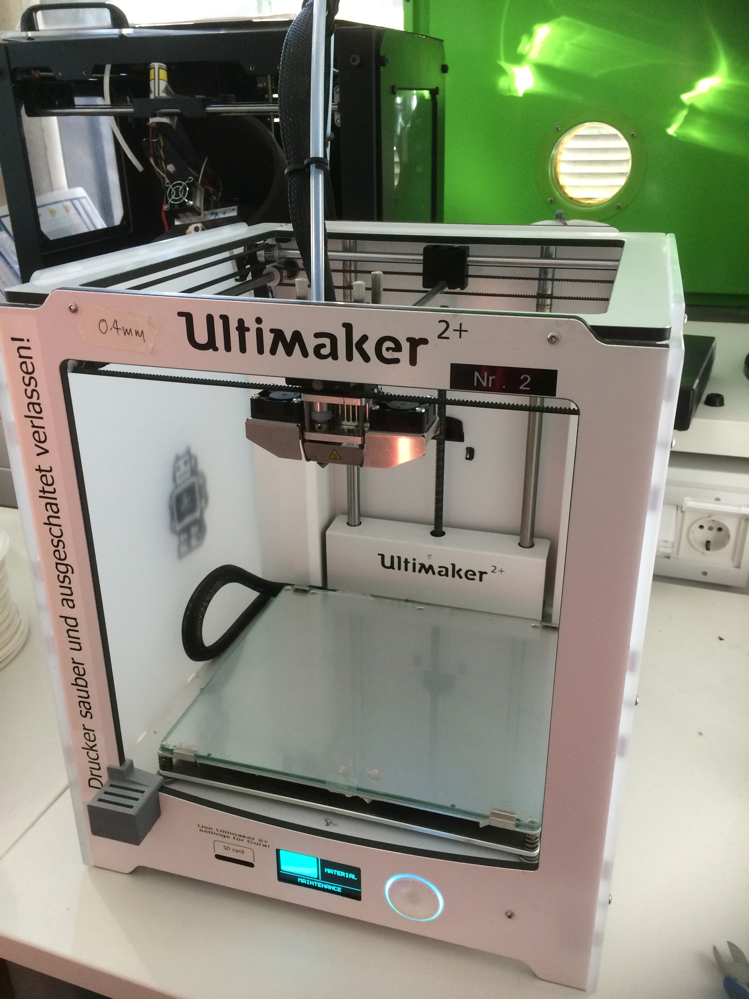
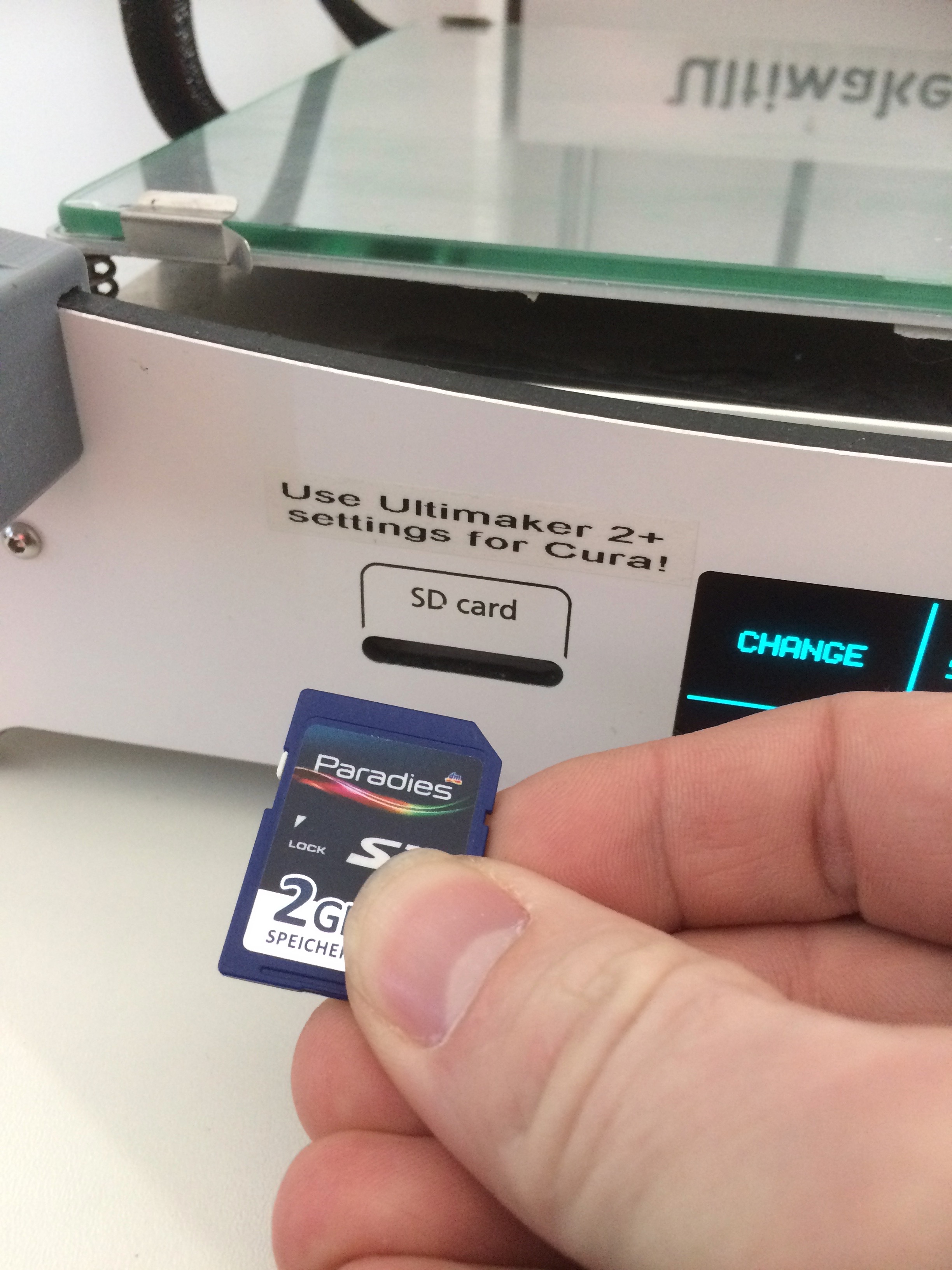
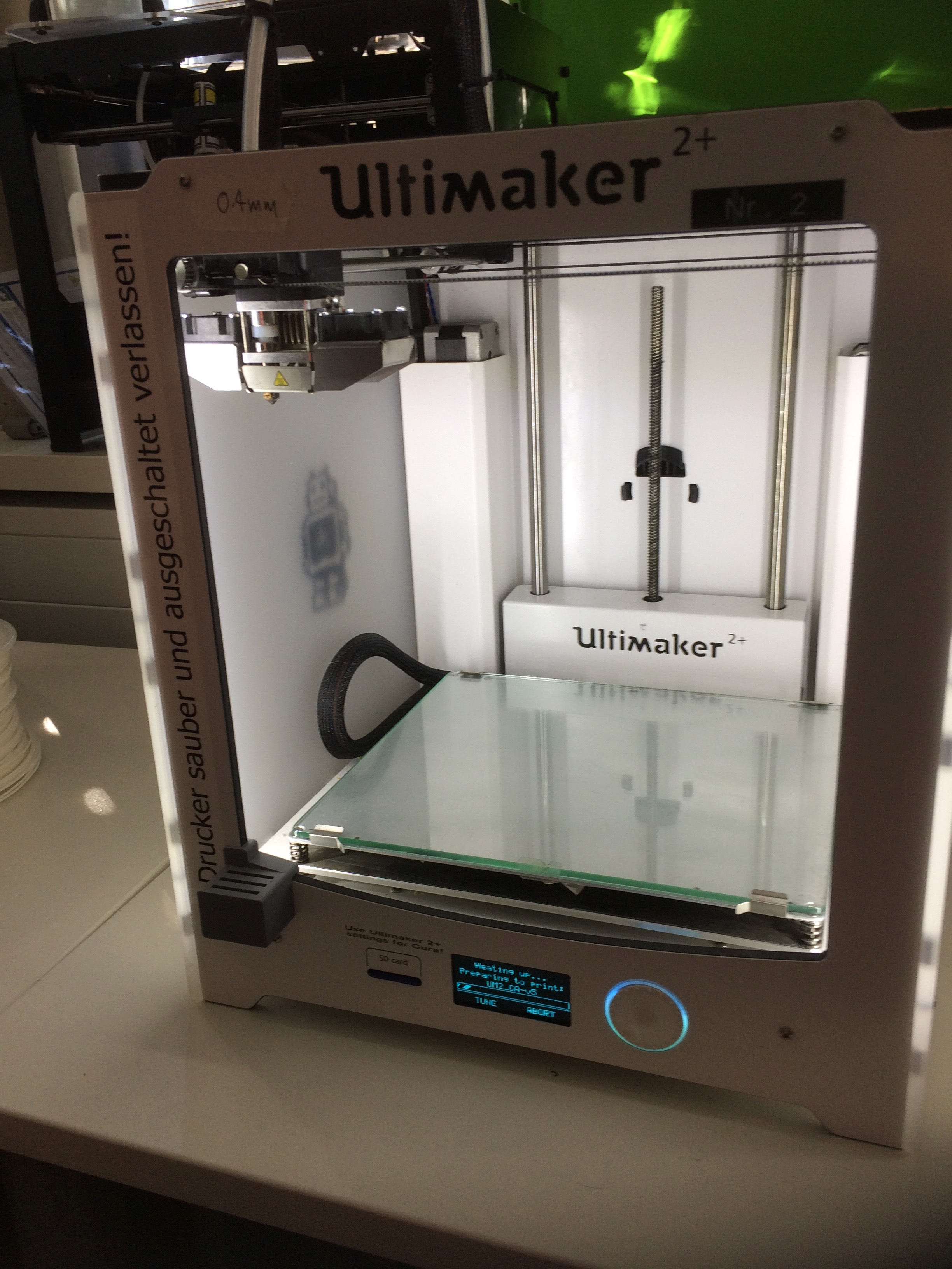
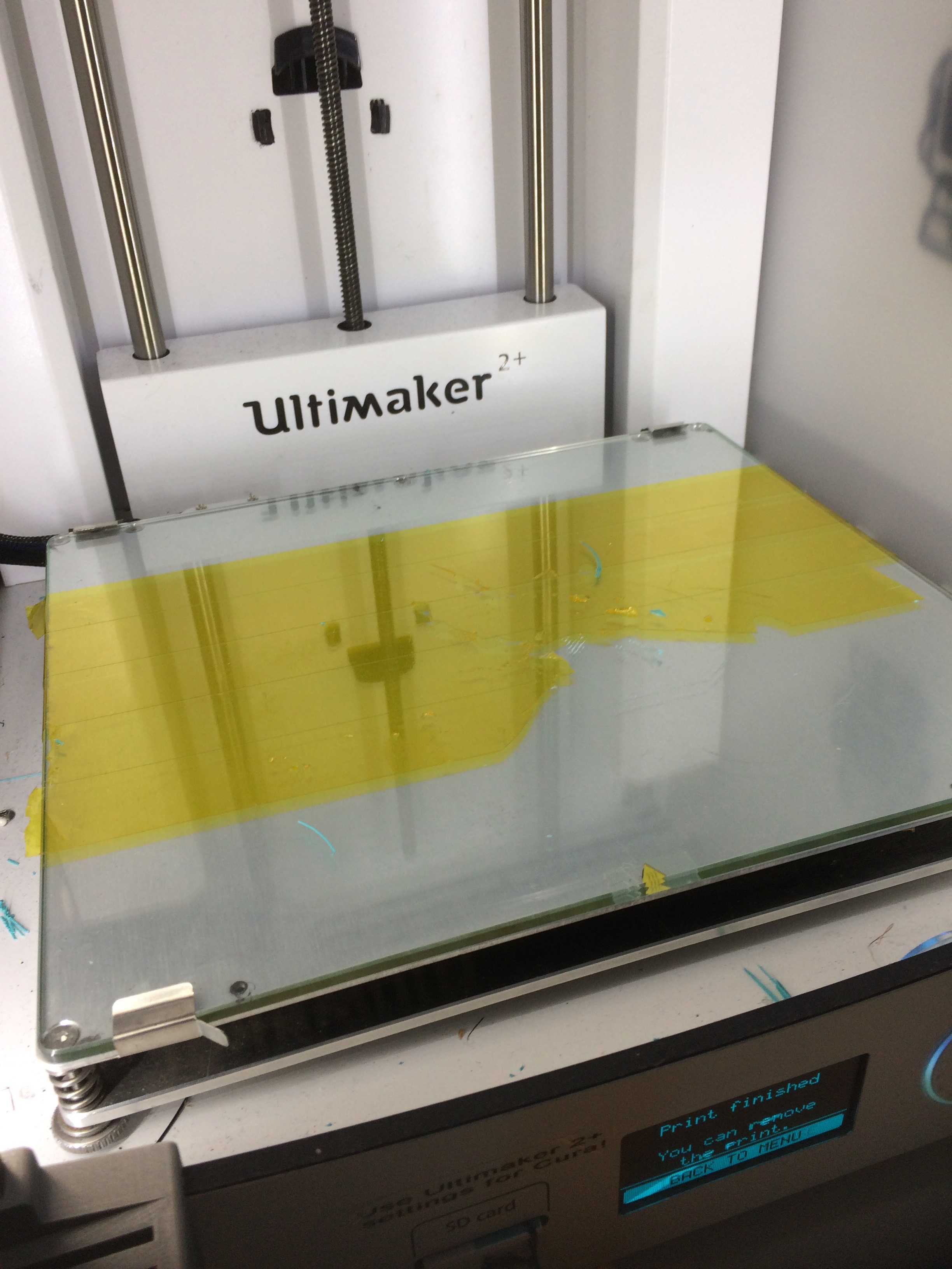
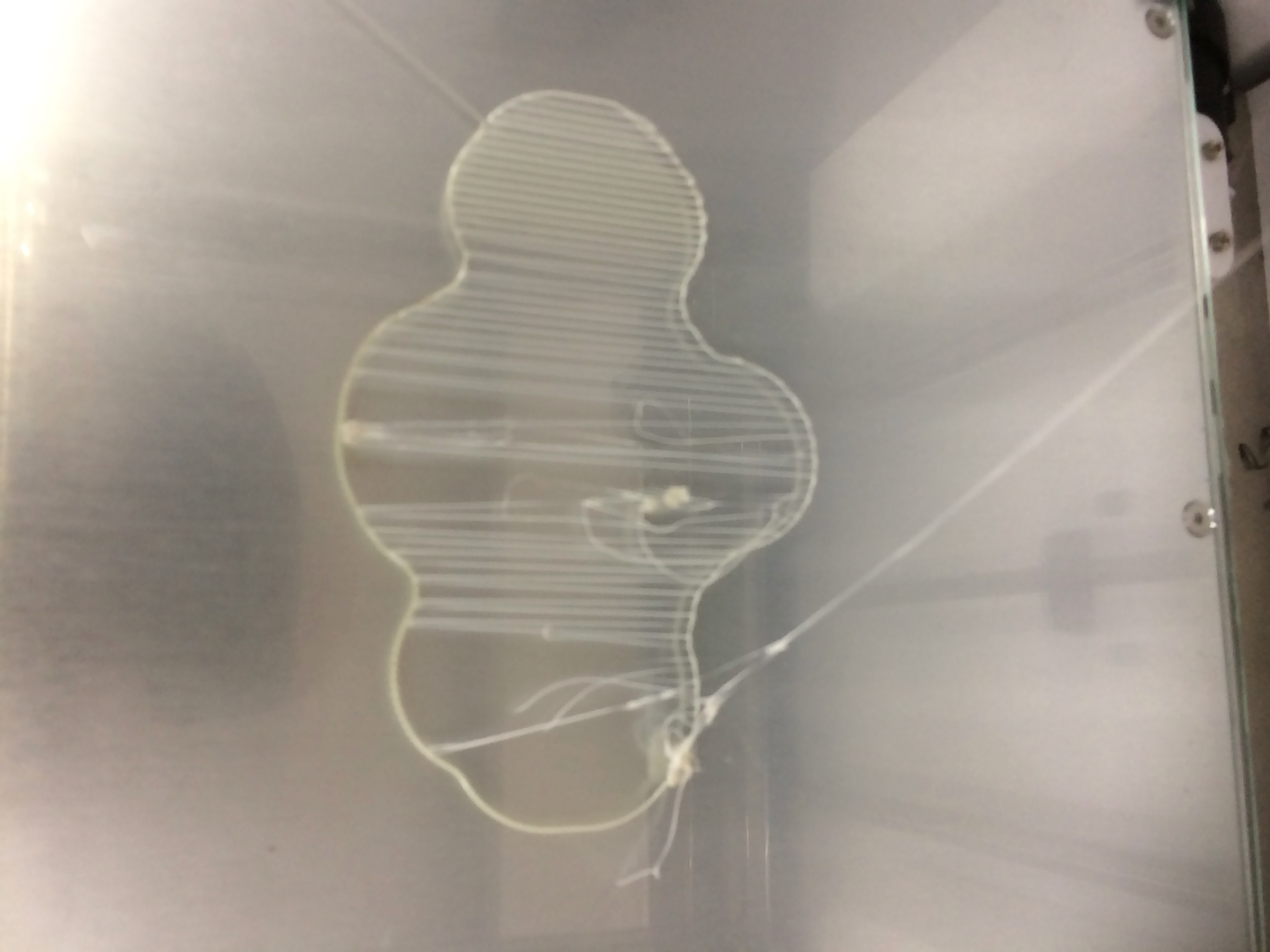
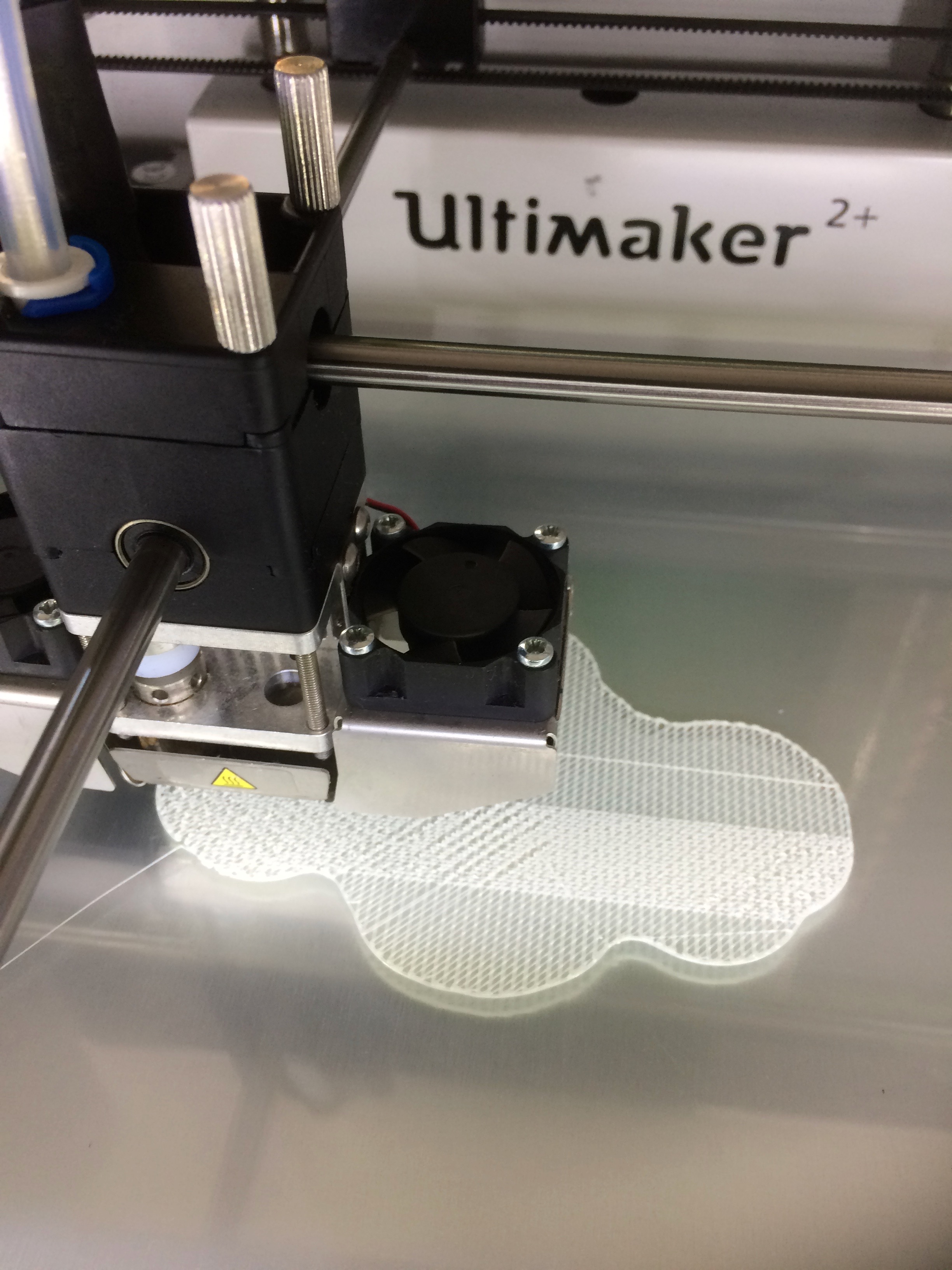
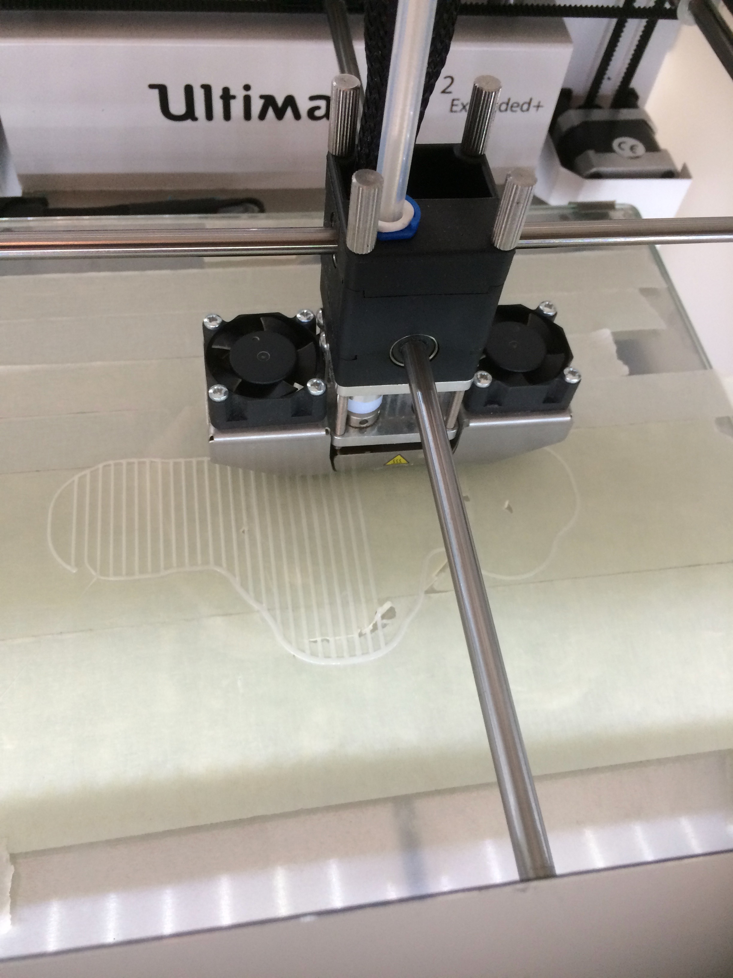
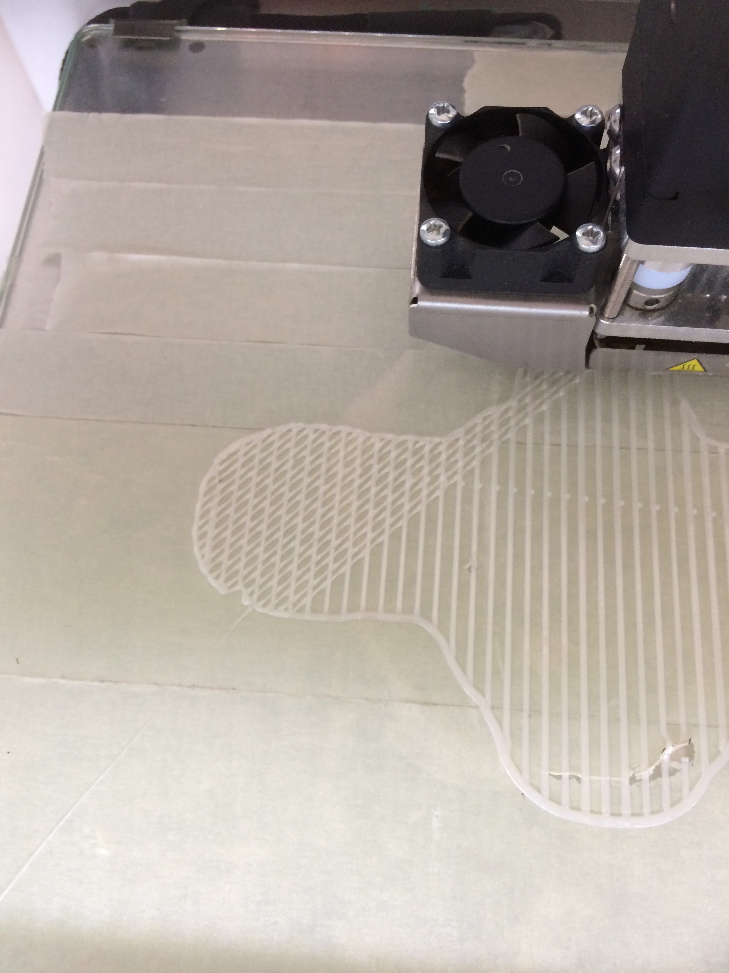
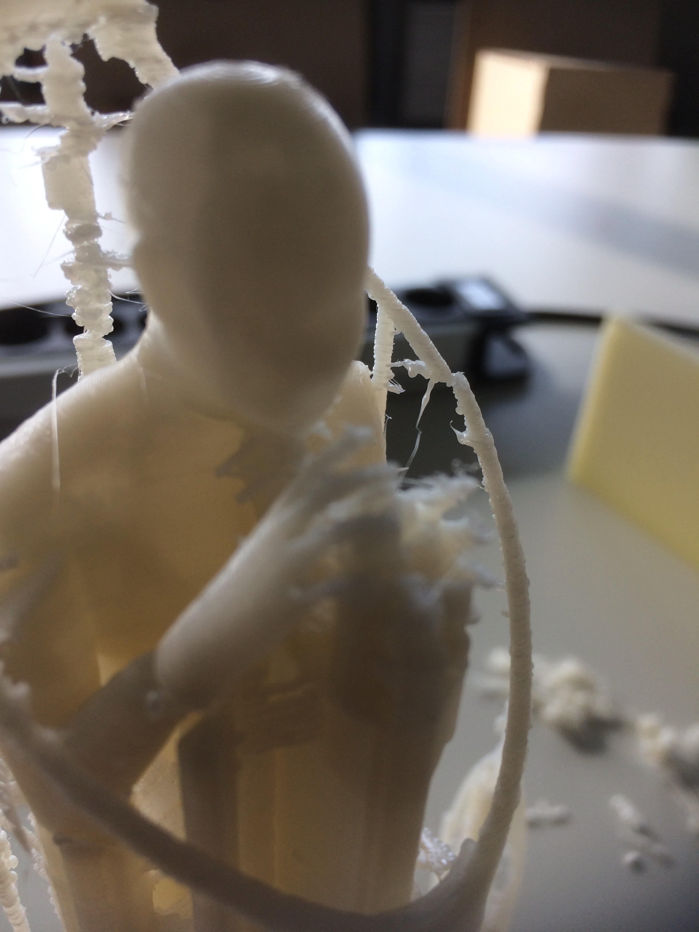
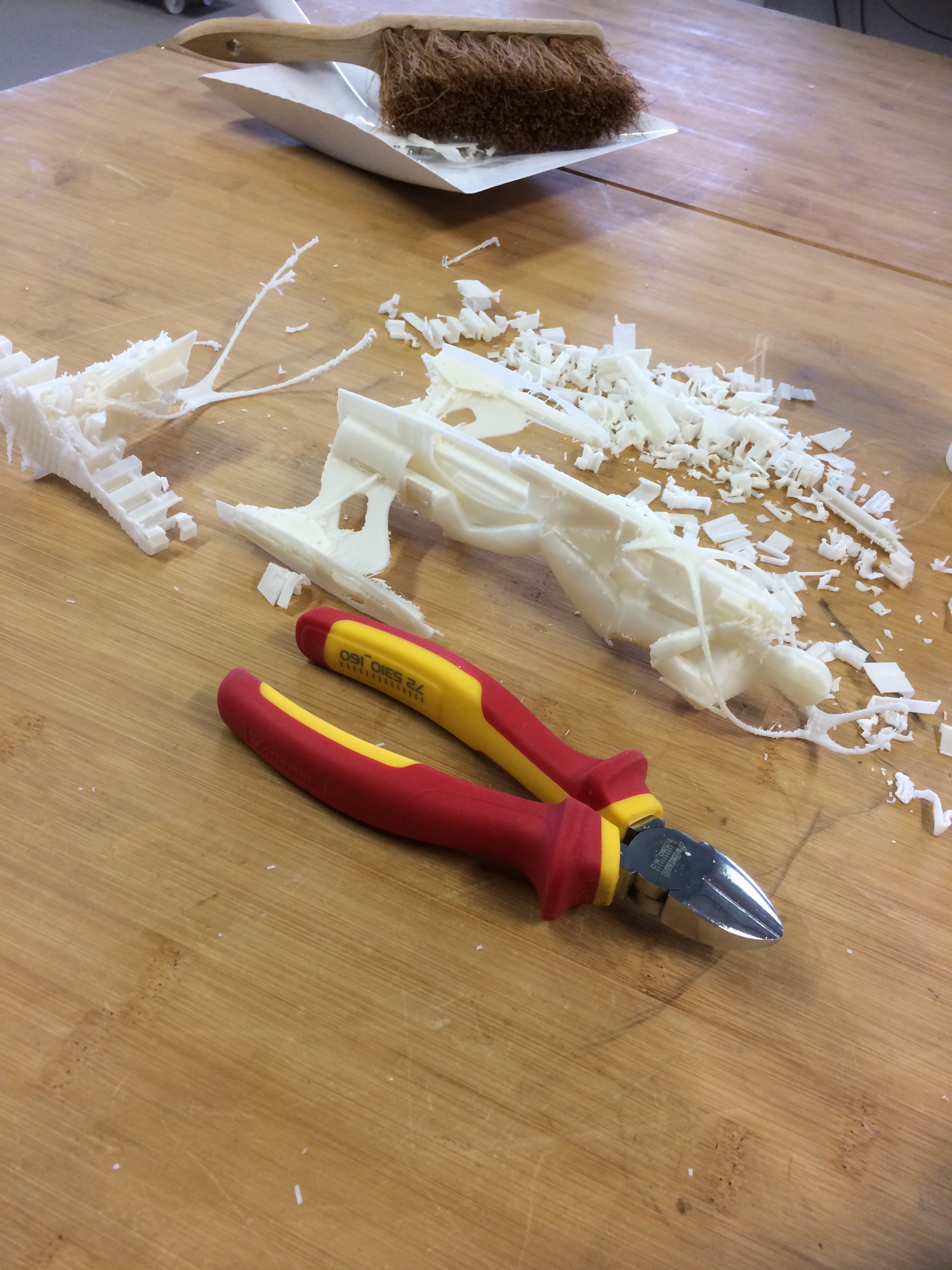
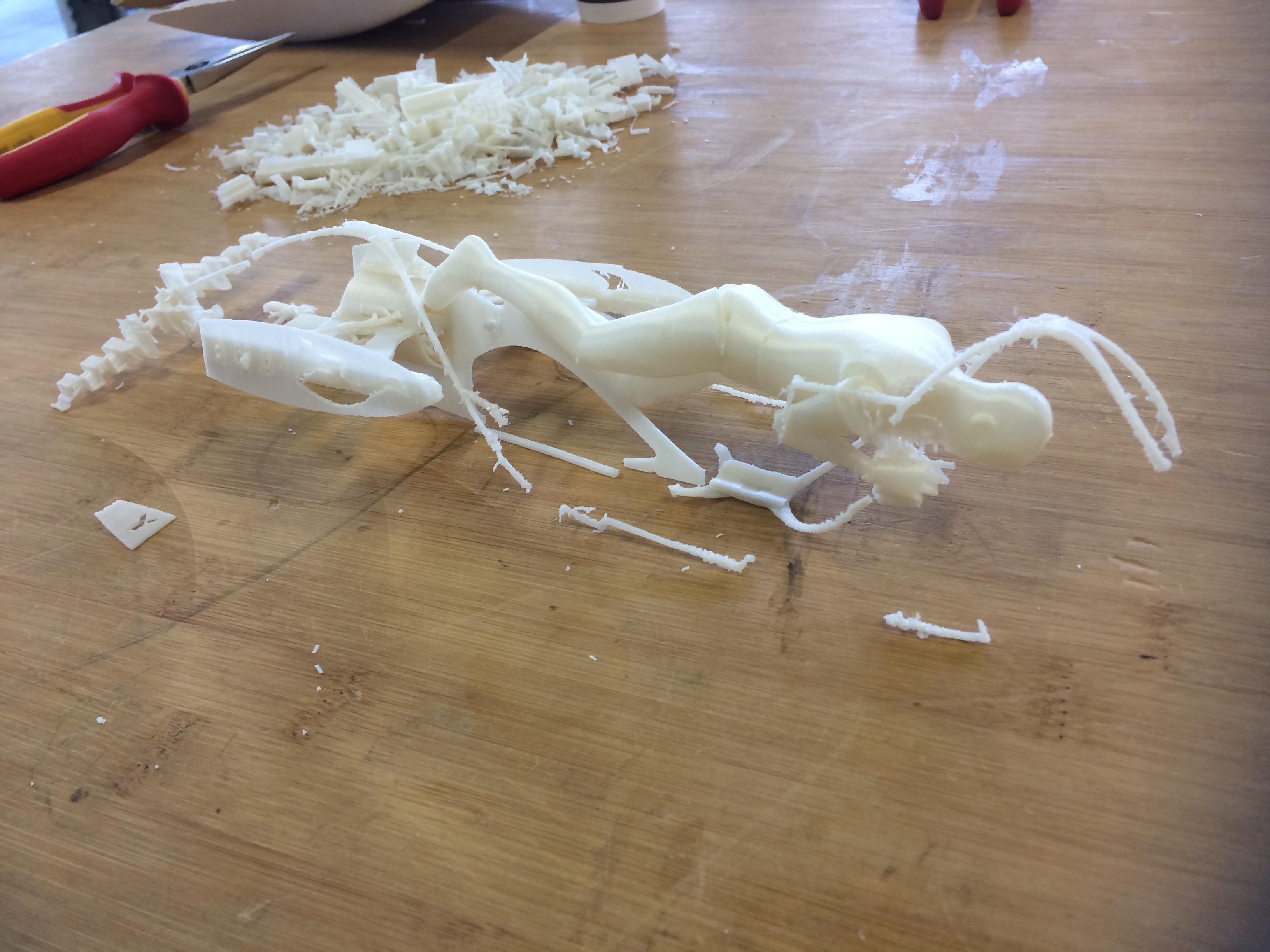
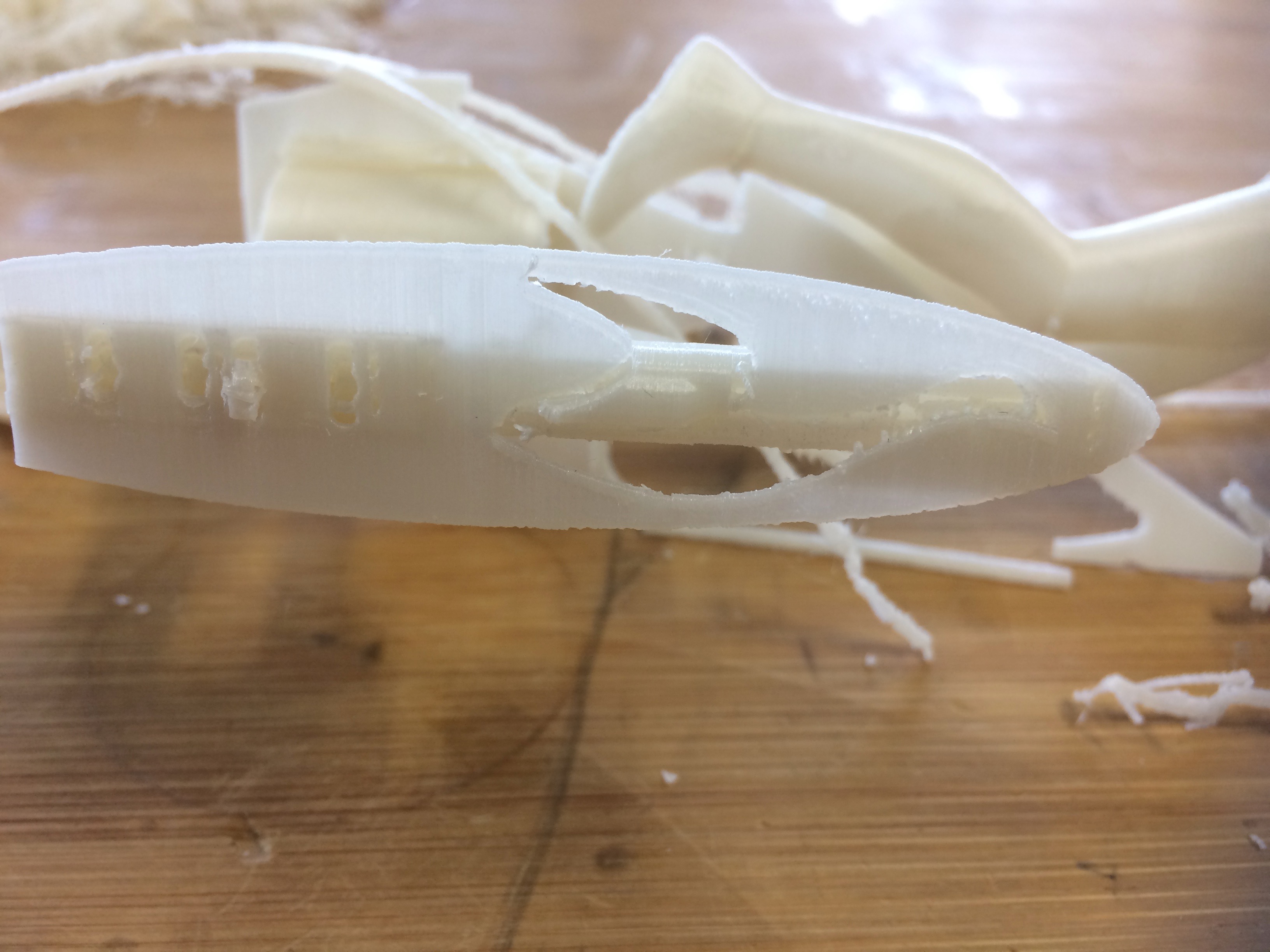
The experiment was not particularly successful in producing a full physical model of the submarine's insides. The complexity of the detail and the fineness of the features were beyond the levels usually attempted in the lab, so the staff were duly impressed with what the machine was able to do. My own pride in the model was lost in the frustrating two-hour battle to remove the supporting material which broke the model in several places, and turned out not to be removable in others.
Next time I print a model like this, I'll go back to my model aeroplane days and make it or several parts fitted with alignment tabs. I'll also need to pay more attention to the separation between the support material and the model. Somewhere in the default settings I accepted in the slicer was a way to make my life easier at the end.
Something that occured while I was breaking the model: it would be good if there was a module for Solidworks that allowed the designer to determine the shape of the support material. I'm imagining a tool akin to the sheet metal tool which produces a default scaffold to modify, and which analyses the schaffold provided to show where it will likely fail.
Trying again, less complexity
Realising that I had bitten off more than I could really chew with the complexity of my first attempt, I had another go, this time with just the outer hull of the submarine. Again, the shape could have been made by cutting several parts substractively using a CNC mill, but since I don't have access to one of those, it seems natural to make this object on a 3D printer.
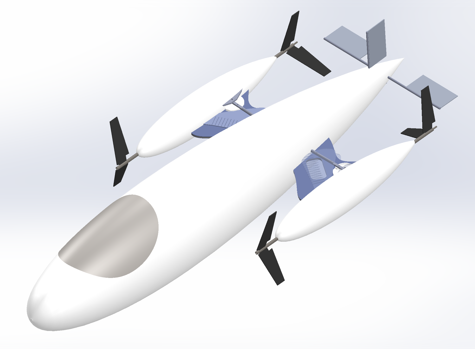
The model is intended to be displayed as a talking piece at the Hannover Fair in April, so it needs to be of a reasonable size, say 40cm in length. It doesn't need much internal strength, since it will just be for show, so I can print it as a shell.
"Wasp" printer - Delta 4070
In addition to the Ultimakers and the high-precision HDMax printer described below, the Kamp Lintfort FabLab has a wasp printer (I've forgotten the name of the mechanism) with a working section 40x40x70cm. This machine is ideally suited for printing long objects. Its precision is intermediate thanks to the geometrically rigid platform which supports the printing head.
The process for printing on the Wasp is very similar to that used for the Ultimakers. Indeed we use the same software, Ultimaker Cura, just with settings specific to the Delta 4070.
To set up the printer driver, I used Settings:Printer:Add Printer, then gave the printer a memorable name (Wasp - Delta 4070). The machine settings were provided for me by my instructor, who uses the machine regularly for his development work. The two screens of settings are as follows (also reachable via Settings:Printer:Manage Printers):
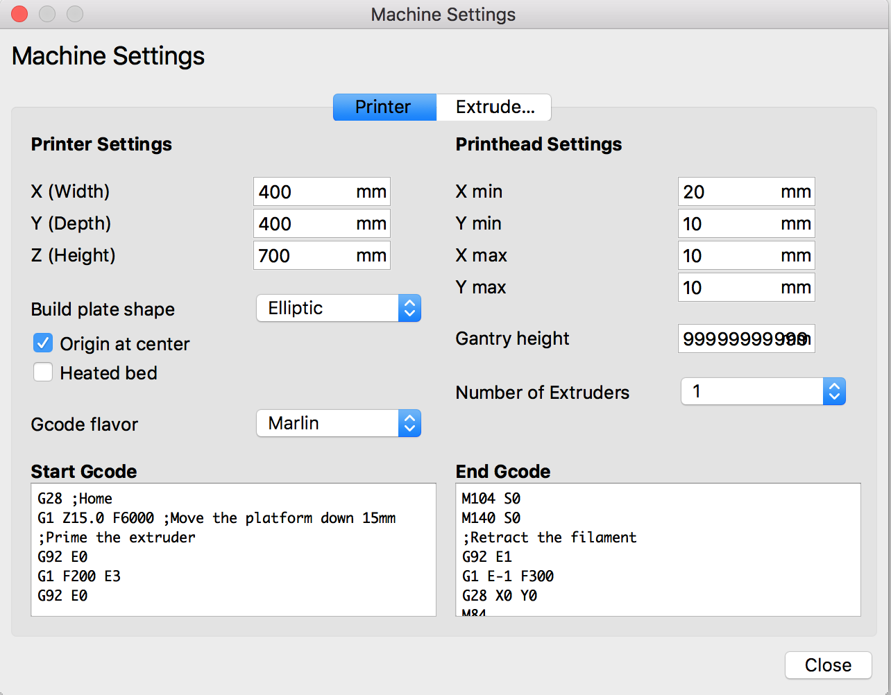 |
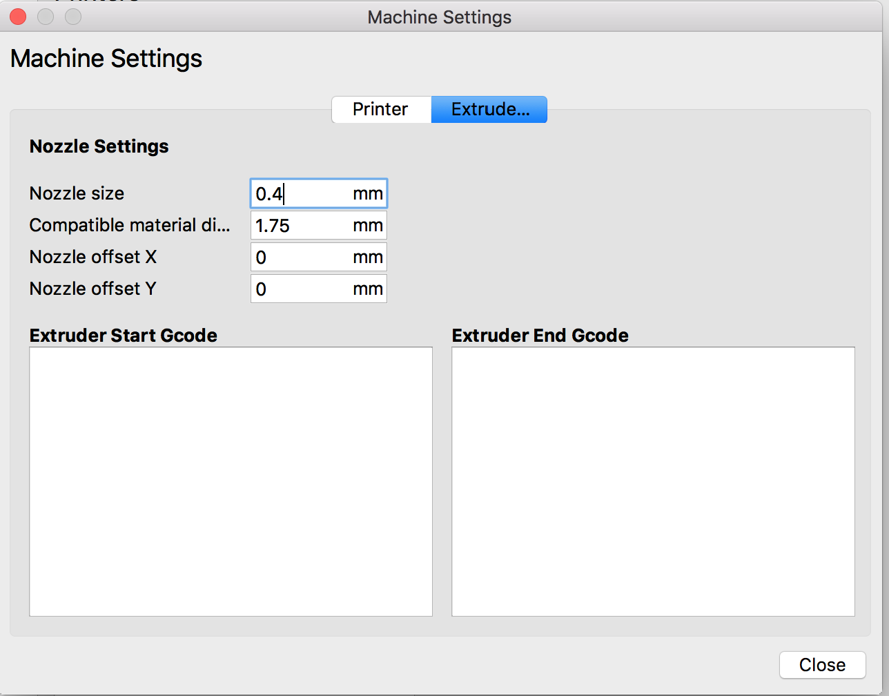 |
The printer settings are, like the Ultimaker, straightforward to set up. To get me started, my instructor provided me with the settings he uses for most of his work by emailing me his "profile", which I then imported using Settings:Profile:Manage Profiles. For the record, the profile looks like this:
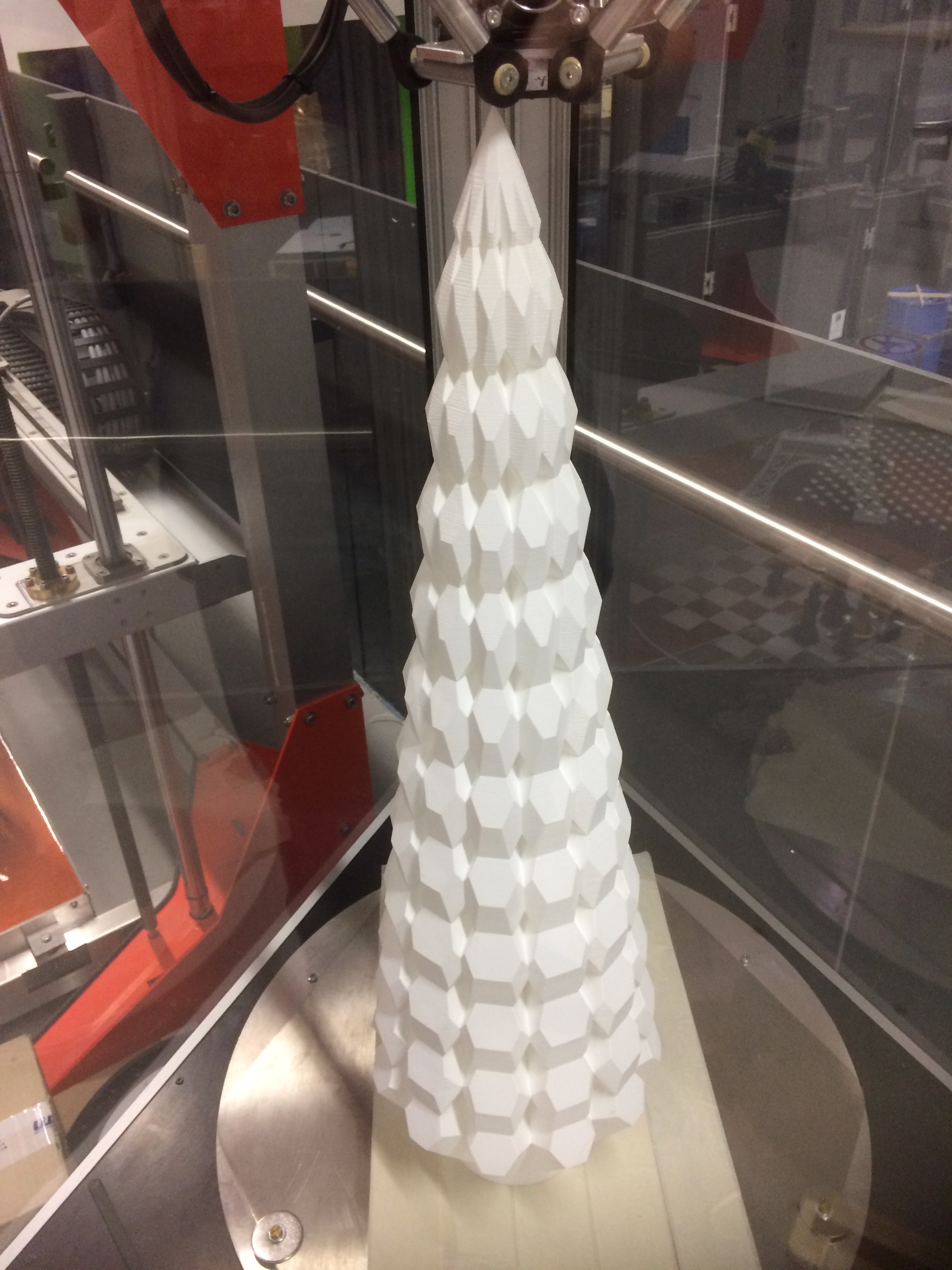
For the job of printing the Hannover Fair talking piece, I ran through the settings and optimised them for printing time and strength (or lack thereof). I used a Christmas tree that was sitting in the lab as reassurance that the final printed model would be rigid enough.
The final settings for the wasp printer looked like this:
| Quality: Layer Height | 0.1 mm |
| Quality: Initial Layer Height | 0.25mm |
| Shell: Wall Thickness | 1.2mm |
| Top/Bottom Thickness | 1.2mm |
| Infill Density | 5% |
| Infill Pattern | Concentric |
| Gradual Infill Steps | 0 |
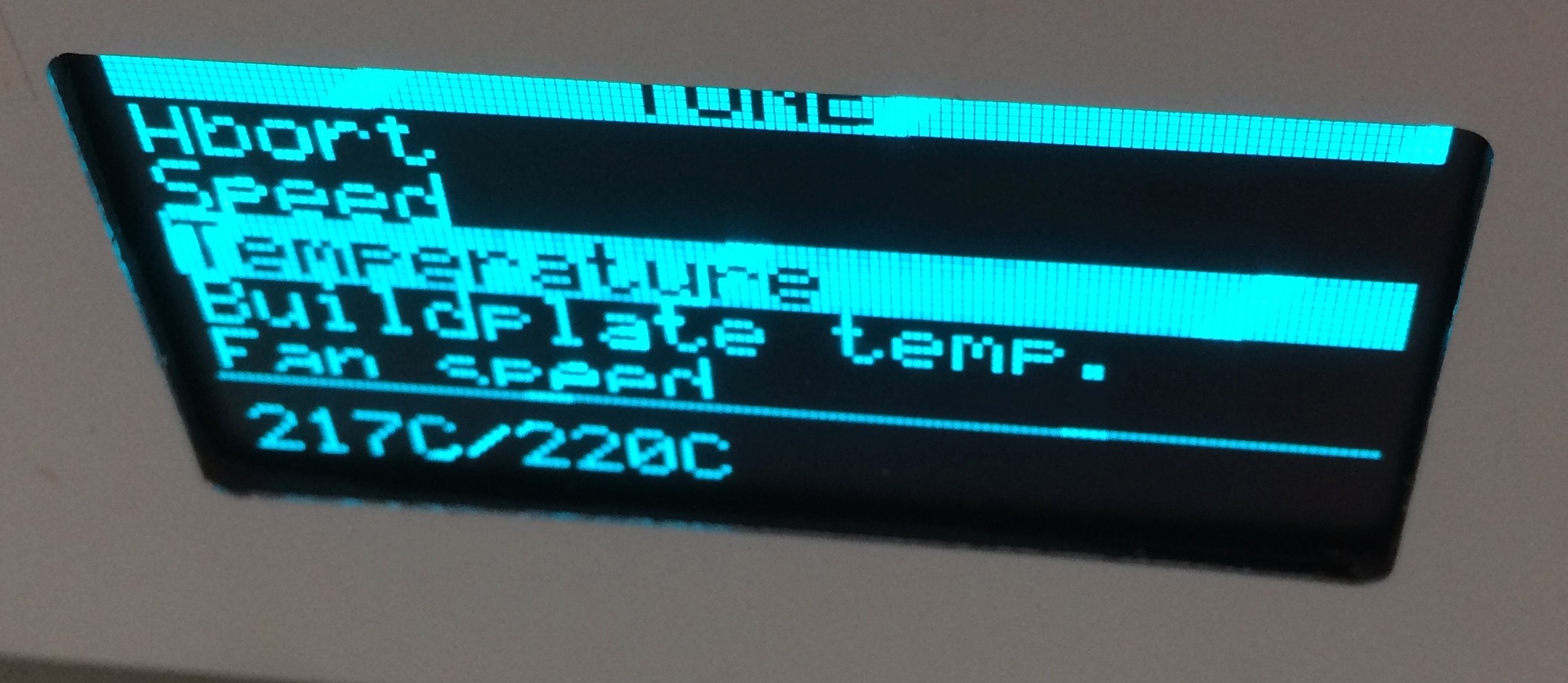
| Material: Printing Temperature | 210 °C |
| Material: Diameter | 1.75mm |
| Material: Flow | 100% |
| Material: Enable Retraction | TRUE |
| Speed: Print Speed | 80 mm/s |
| Speed: Travel Speed | 150 mm/s |
| Speed: Initial Layer Speed | 20 mm/s |
| Print Cooling | Enabled |
| Support: Generate Support | TRUE |
| Support Placement | Everywhere |
| Support Overhang Angle | 70° |
| Support Pattern | ZigZag |
| Connect ZigZags | TRUE |
| Support Density | 10% |
| Build Plate Adhesion Type | Brim |
| Brim Width | 20 mm |
| Print Sequence | All at Once |
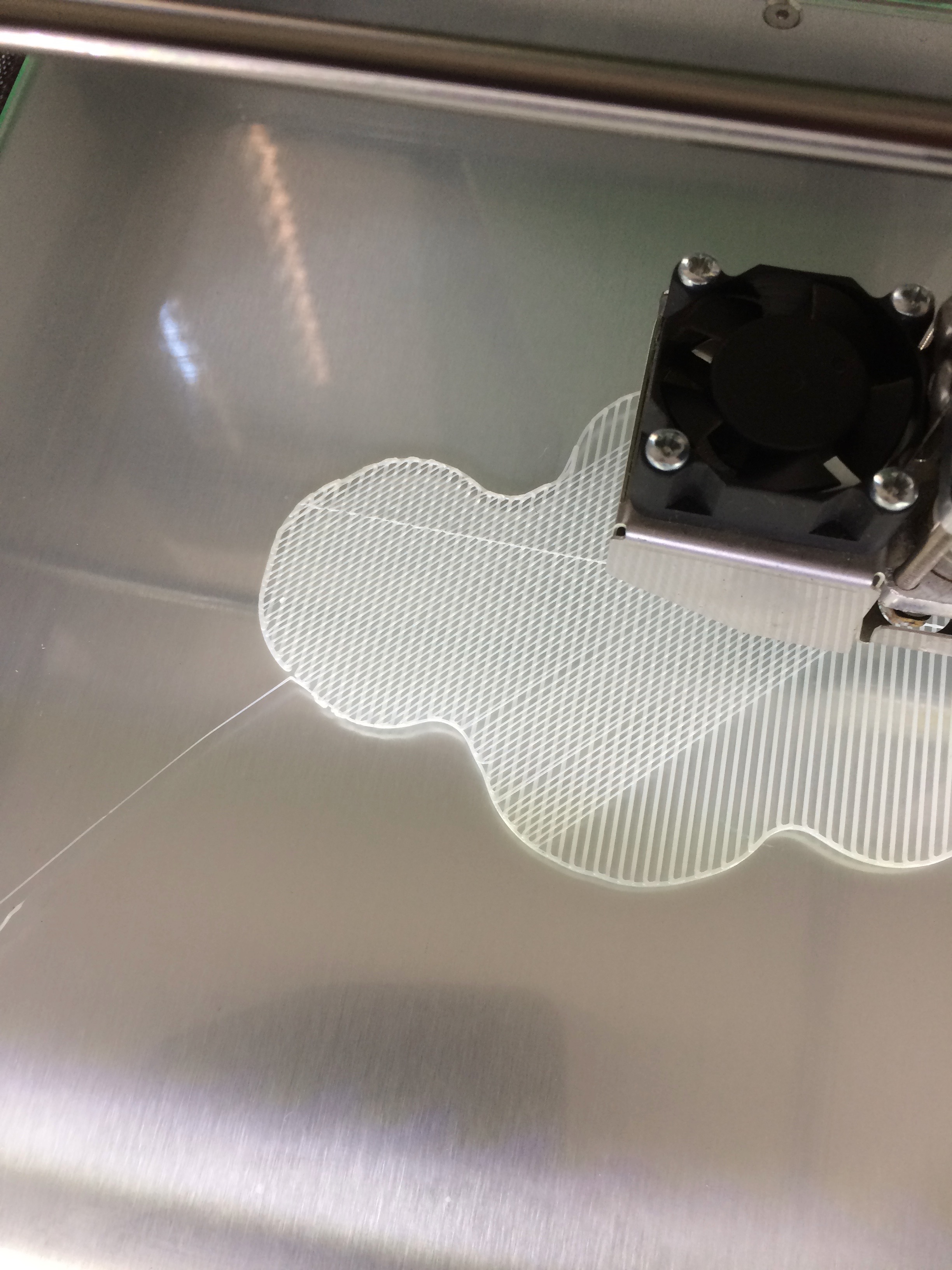
| Spiralize Outer Contour | TRUE |
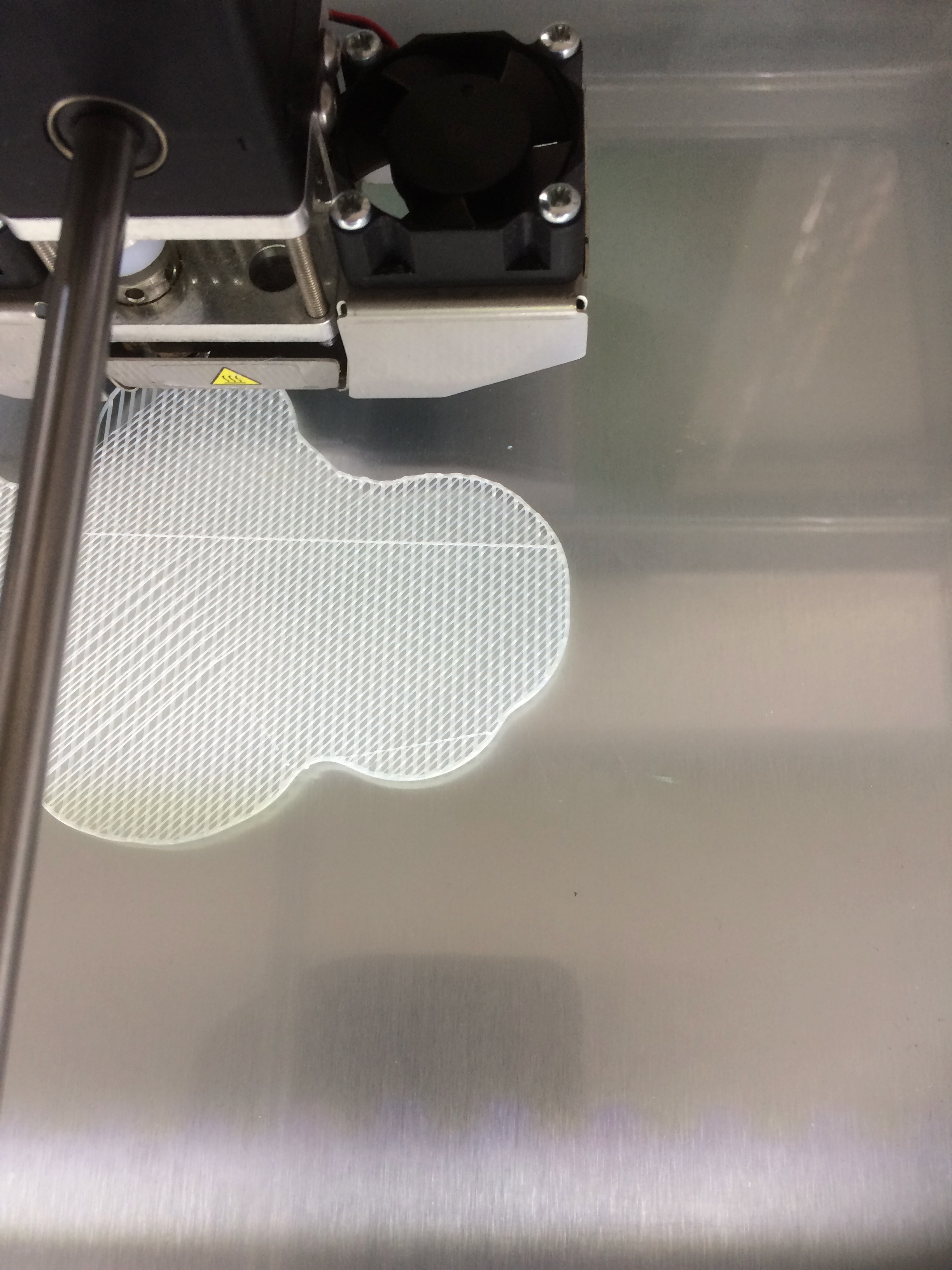
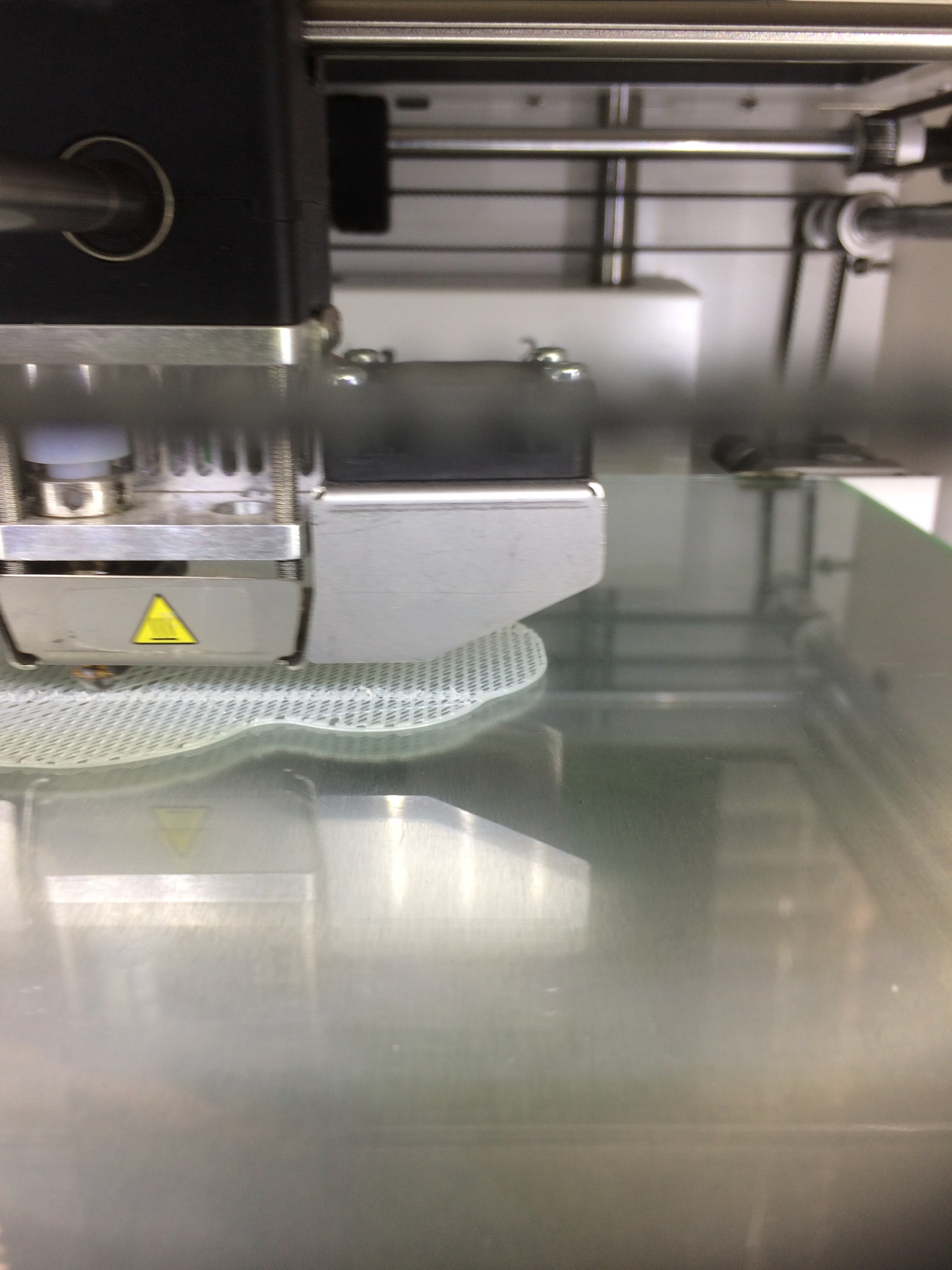
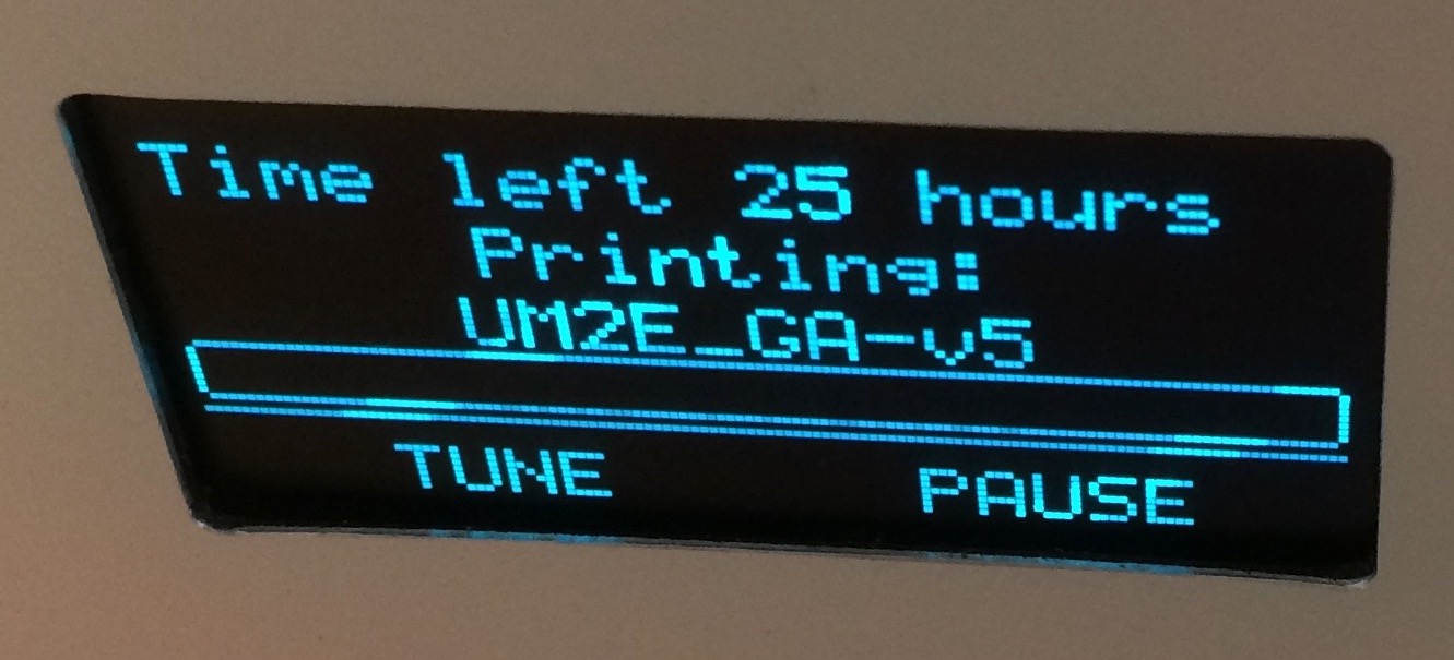
It's the last setting that's the key to keeping the time down. This generates a simple external shell with no support material inside. It will be crushable, but as a static talking piece it will be fine. I tried other infill patterns, and found that concentric was the easiest on the time cost, so if the shell is in fact too flimsy, then that will be the backup plan. The job was estimated to take 14 hours, so I'll see it on Wednesday.
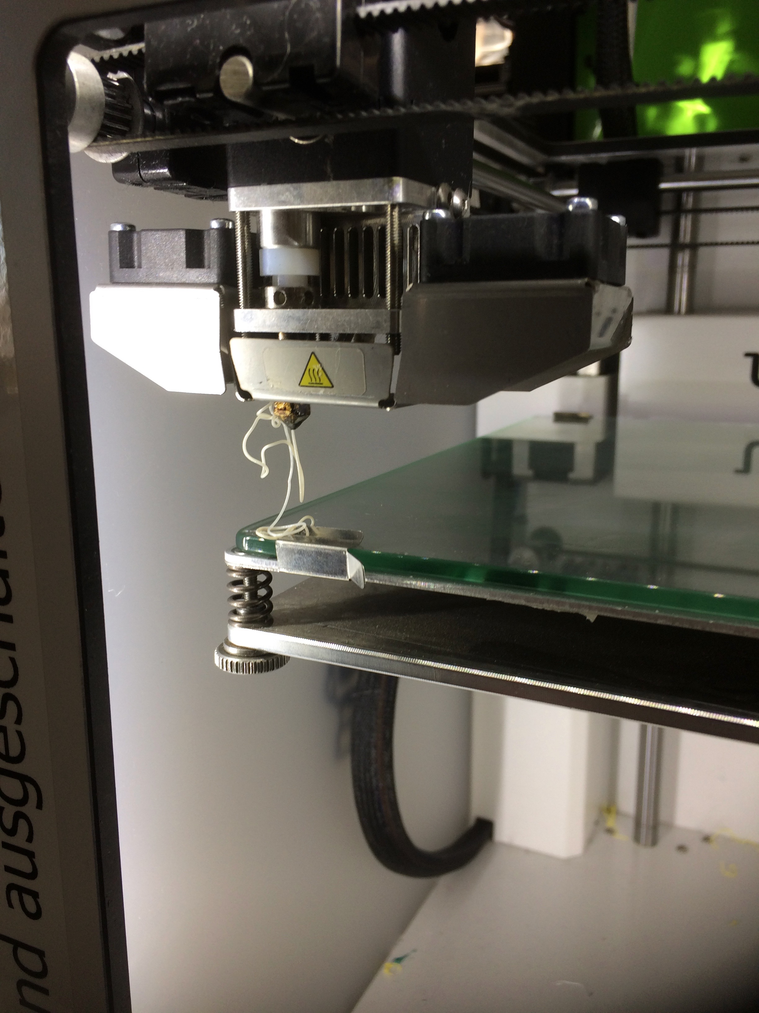
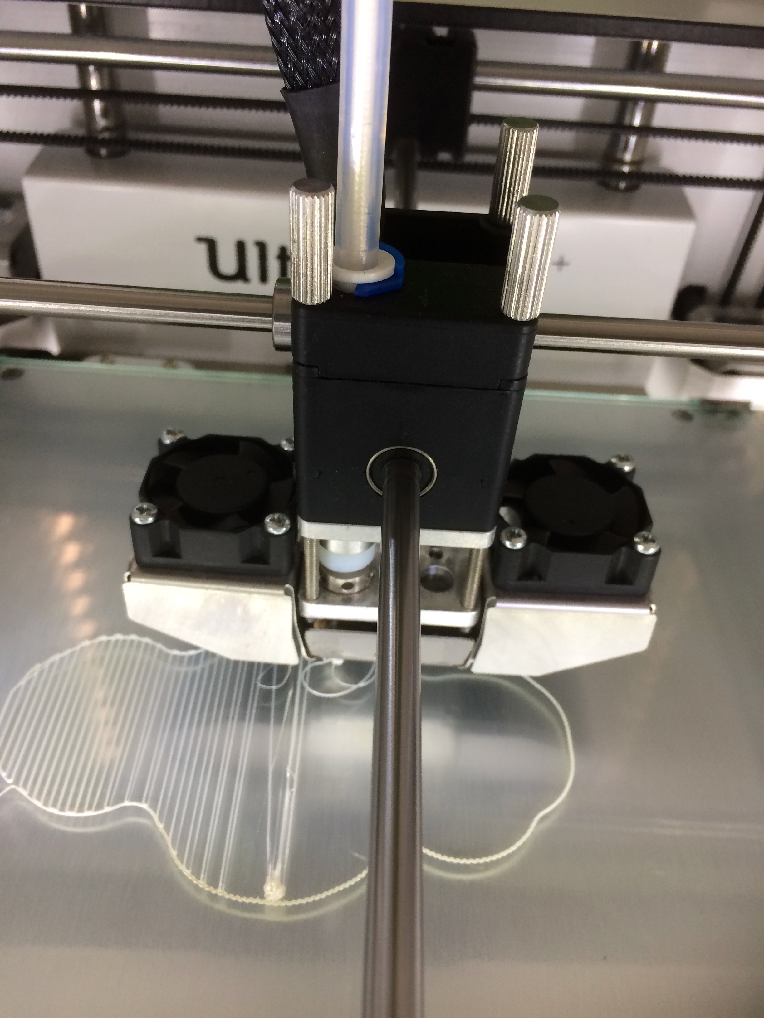
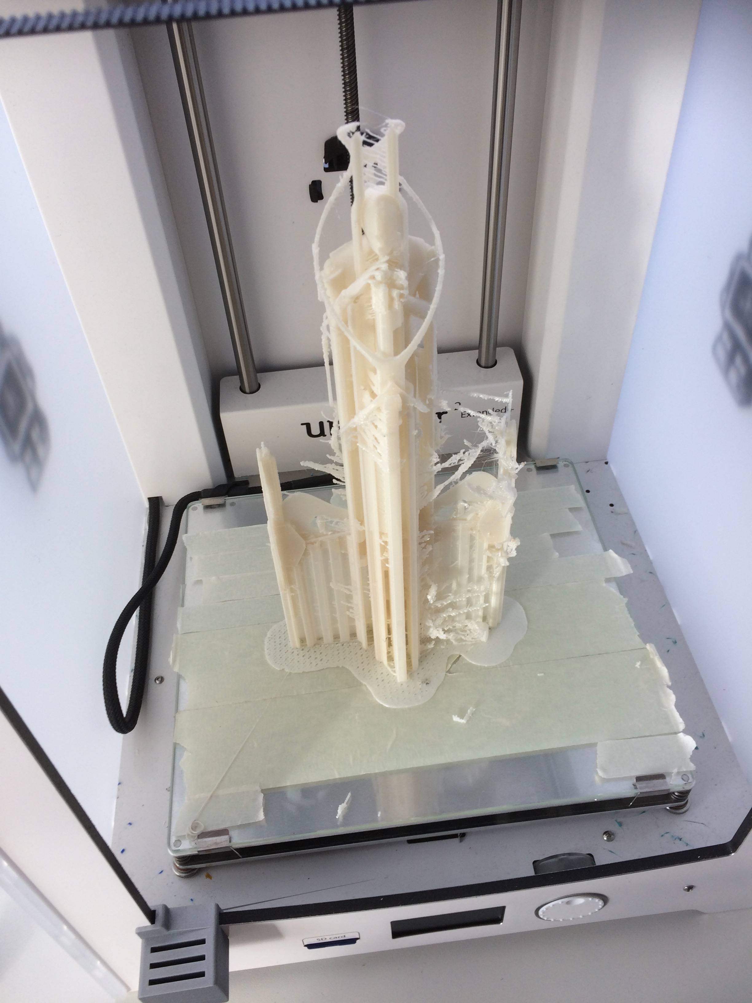
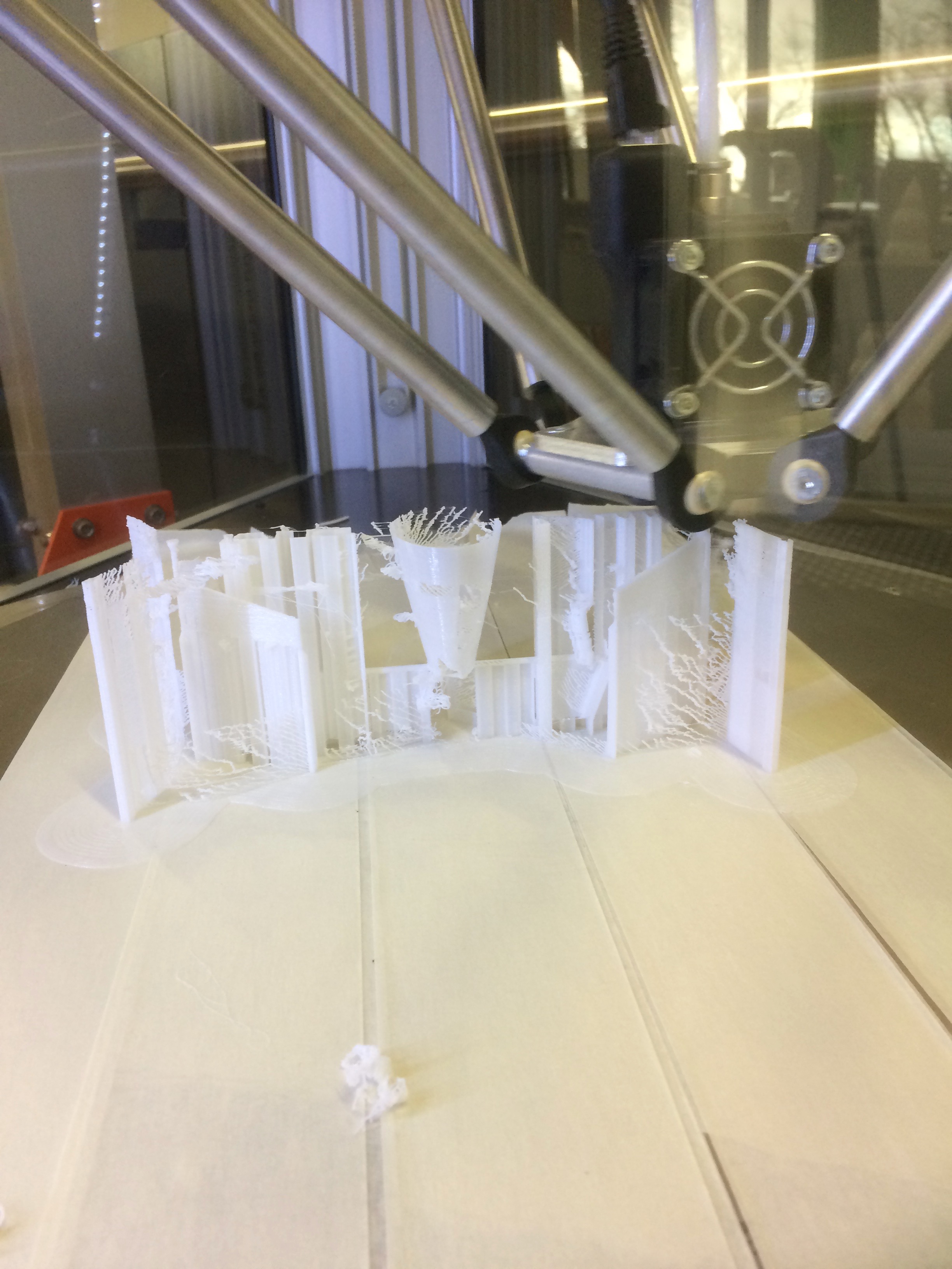
Update at 17:30 Monday. The job is a failure. I'll have to try use the infill after all. Seems I'm really not cut out for 3D printing...
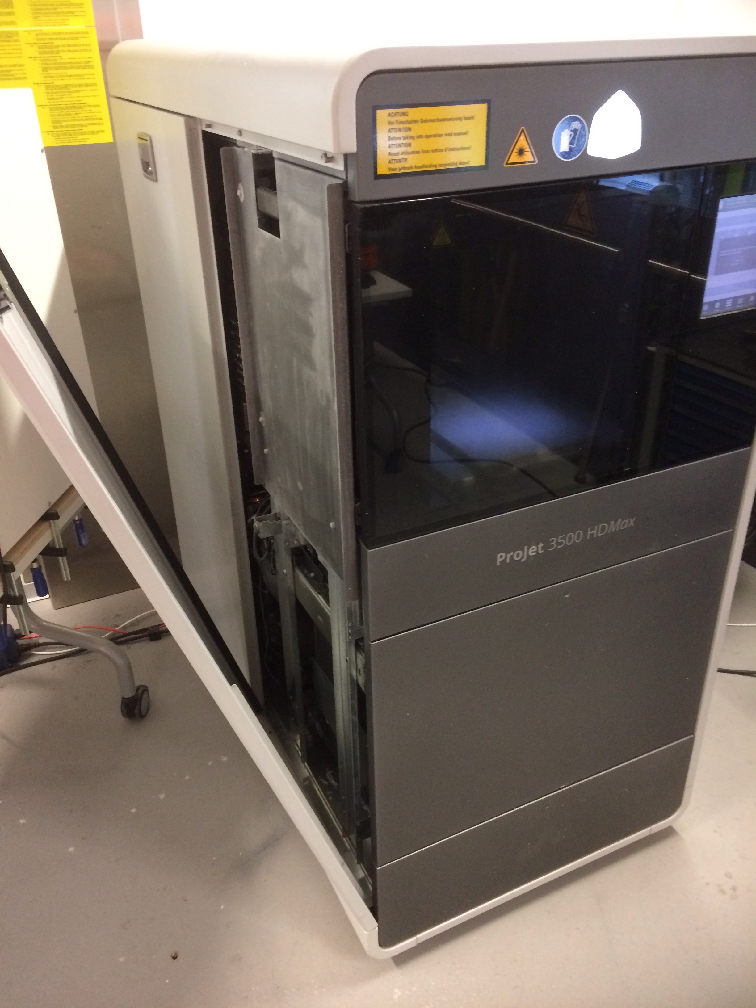
Higher precision - Projet 3500 HDMax
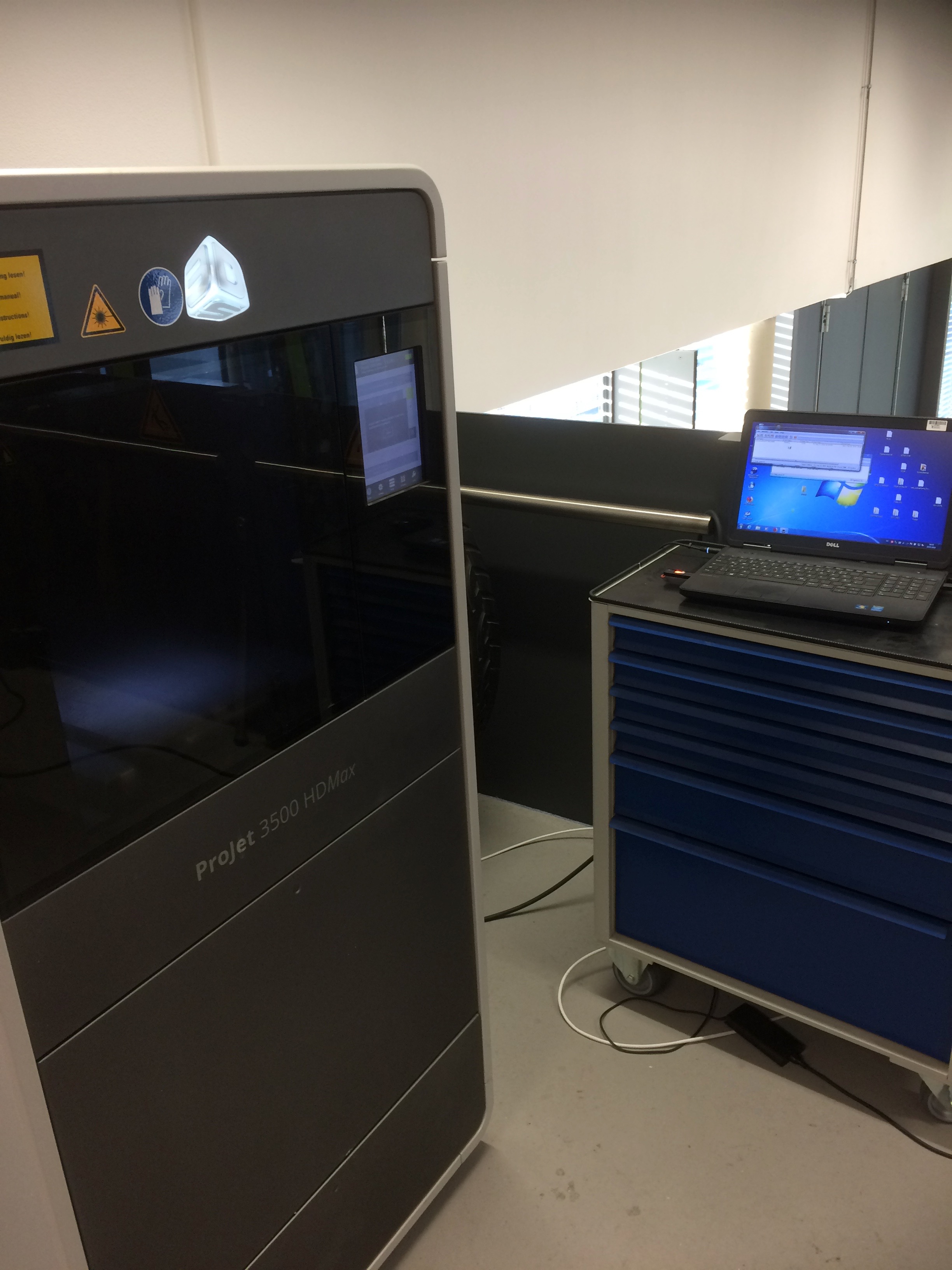
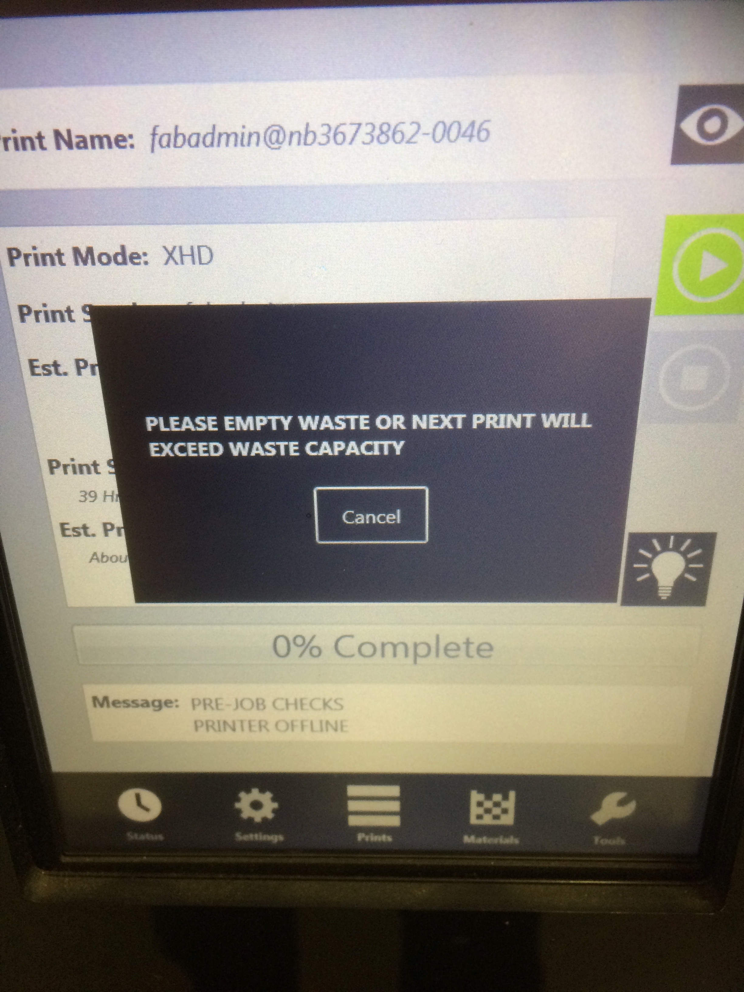
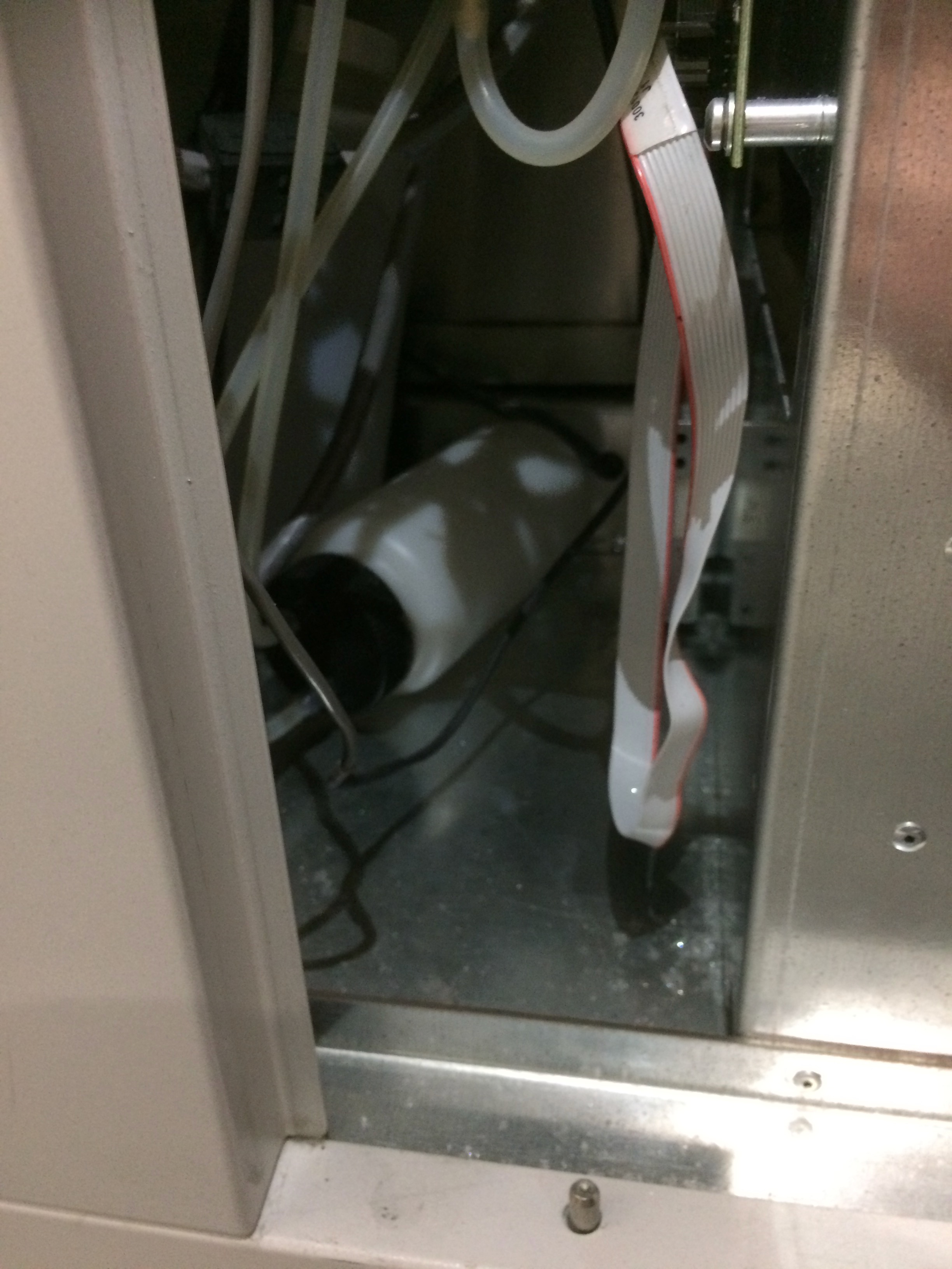
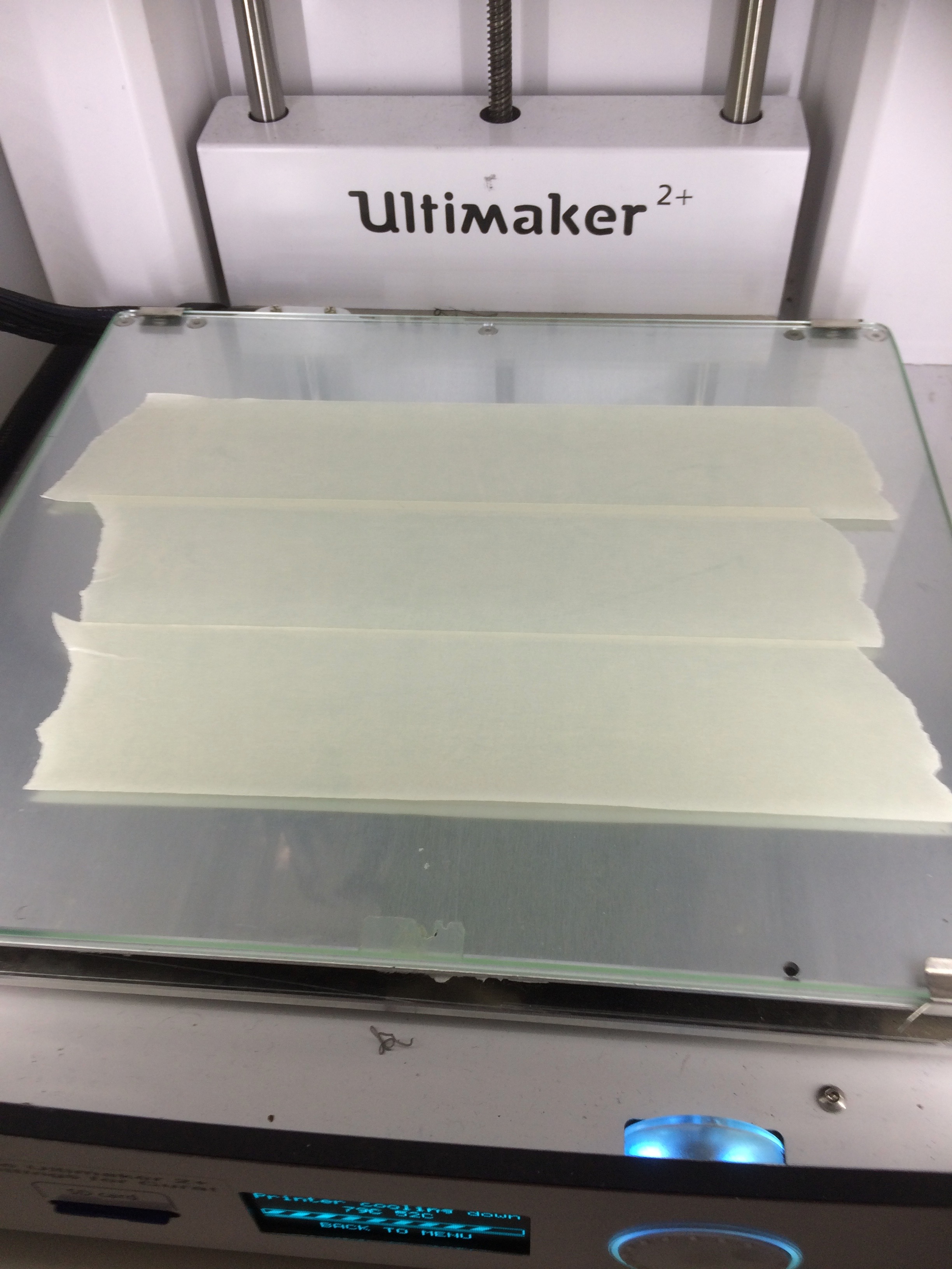
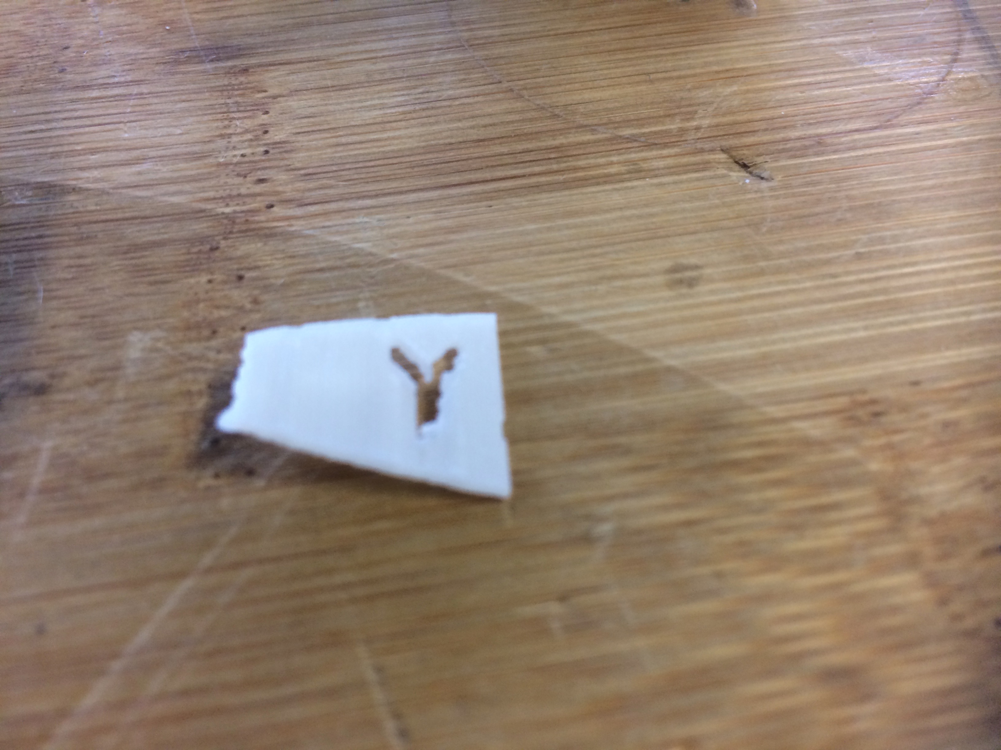
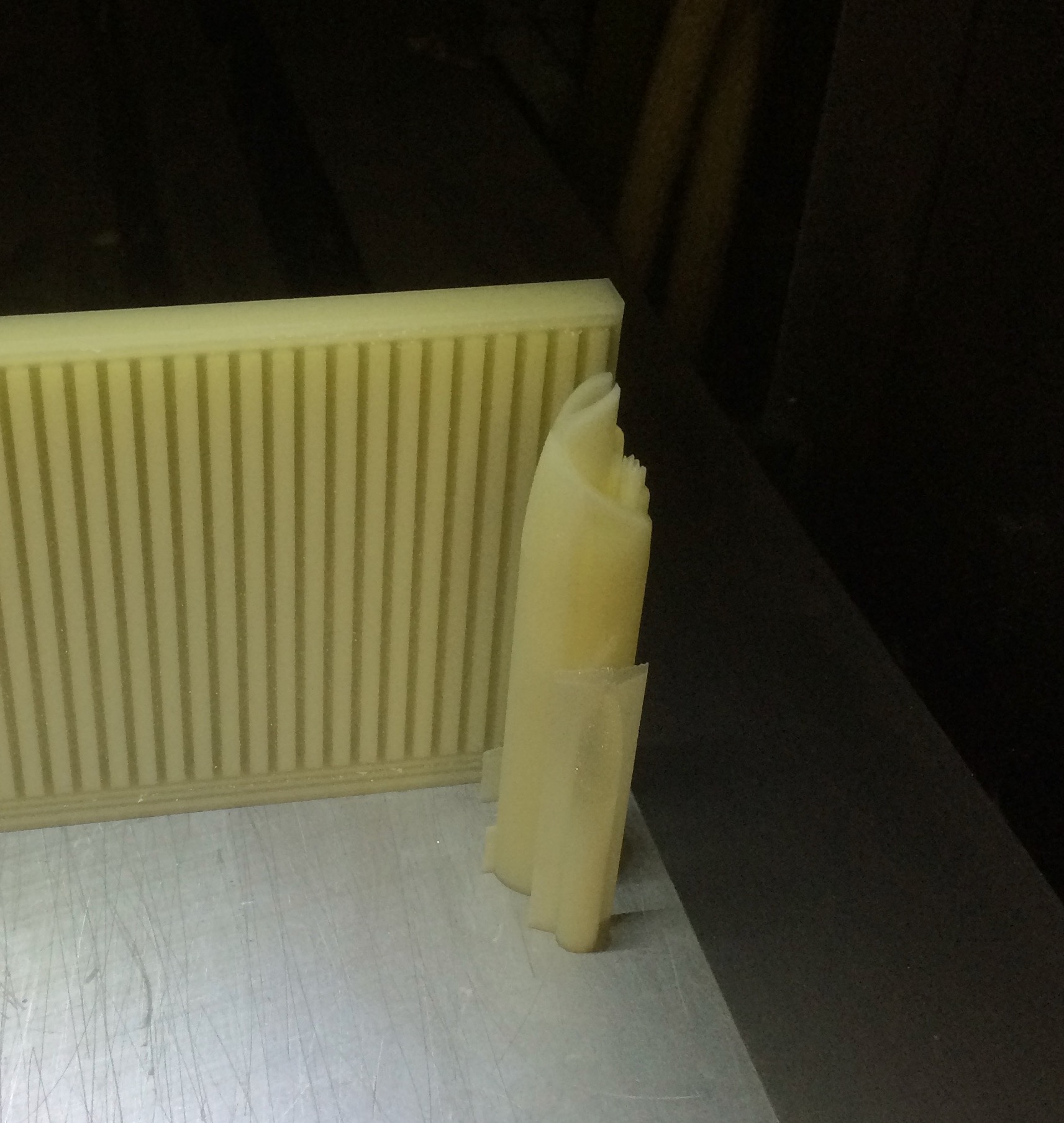
After 3 days of hard work, the machine stopped printing. It left a non-descript cylinder of plastic and wax in its wake.
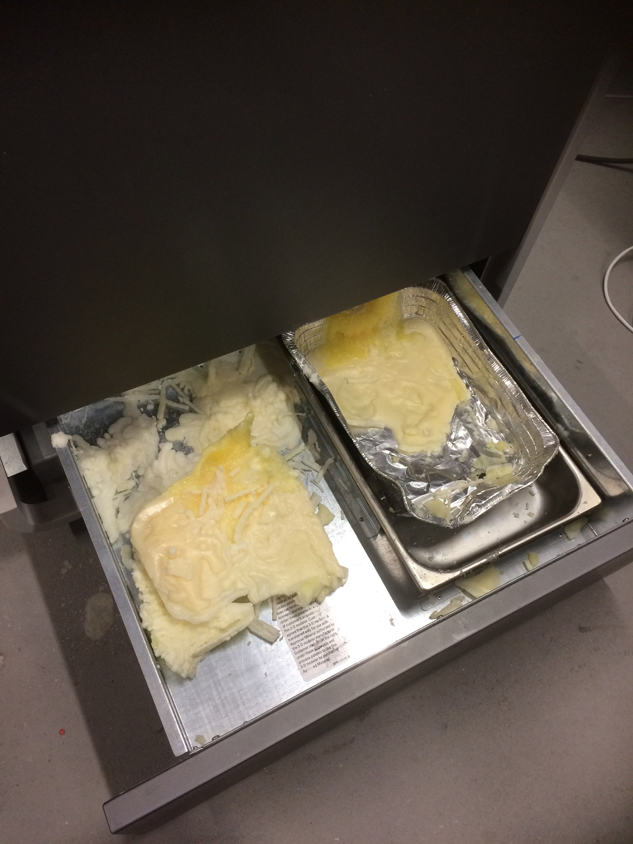
The next step was to fire up the oven to 70°C and place the printed model on a bit of toilet paper on the rack over a collecting tray. The TP was used to capillarily suck the liquid wax out of the harder to reach bits of the model.
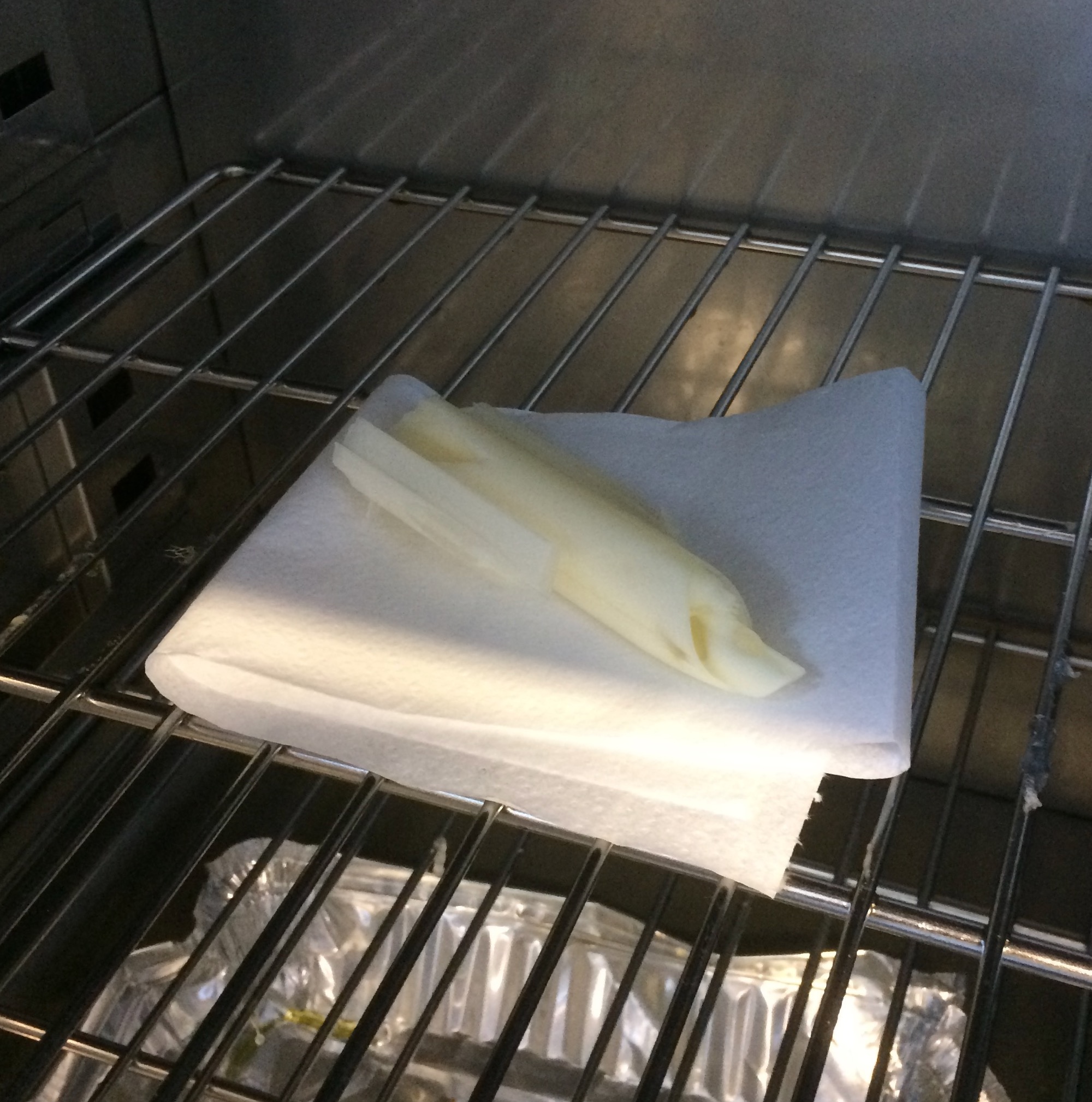 |  |
Then it was time to be patient, and find something else to do (like break the support material off the other model).
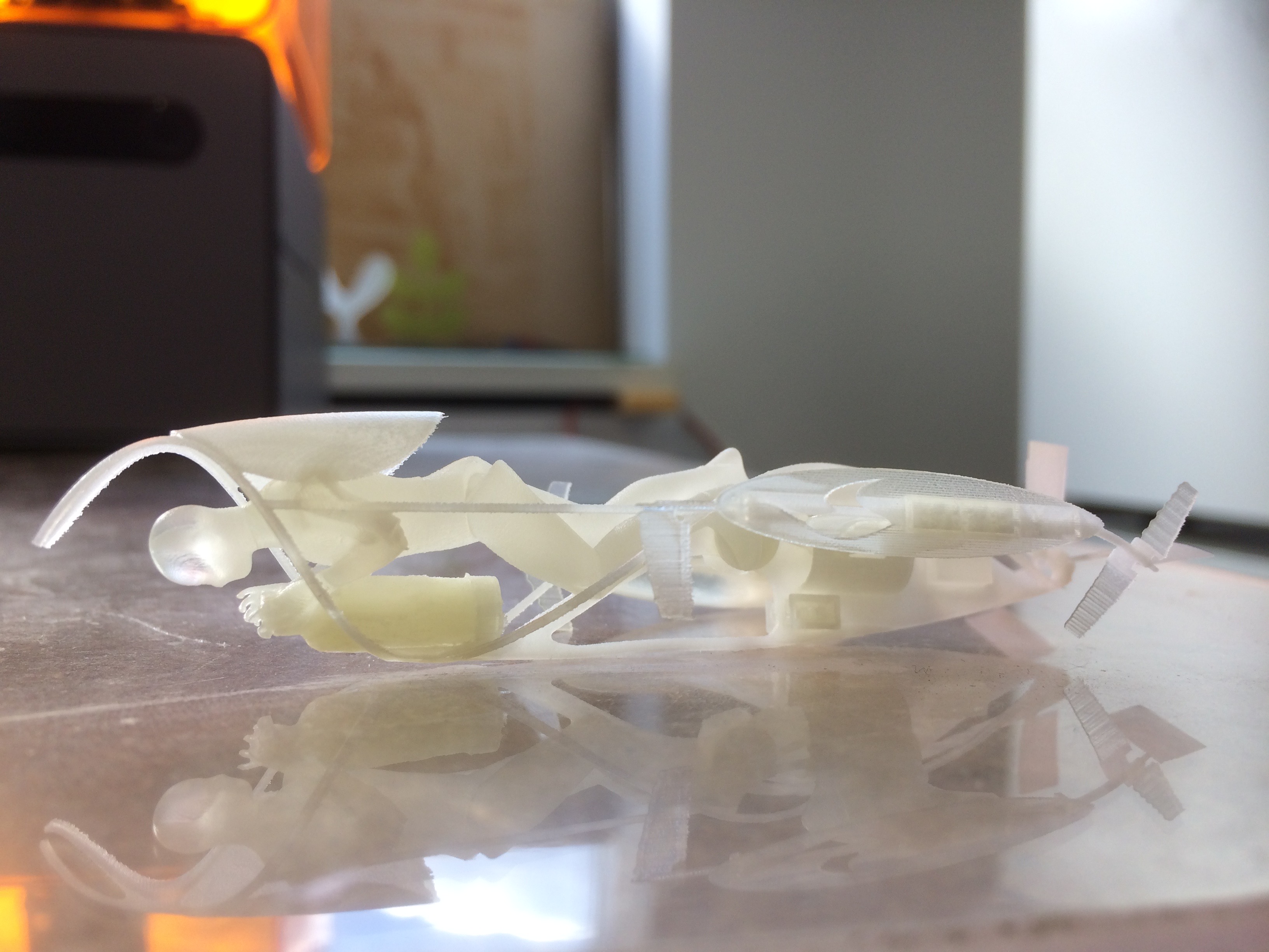
The end result of the high res scanner is gorgeous, but it did have to be kept small due to cost. The phase change method for removing the support material was a big improvement over the horrible mechanical work I had to do on the Ultimaker model.
I'm told that it is possible to print working mechanisms with this printer, so I might be back shortly with a model of one side of the submarine propulsion system. There are some really interesting elements in that, which it would be really neat to show in a real working model. The tick apparently is to design the assemblies in Solidworks with parallel but not coincident mates.
3D Scanning
The first of the 3D scanners we tried in the lab runs on an iPad (iSense). It worked really well for scanning a person sitting in a chair in a relatively uncluttered room, but it didn't work at all on a glossy black steel spaceframe. Here's the story of what we got up to.
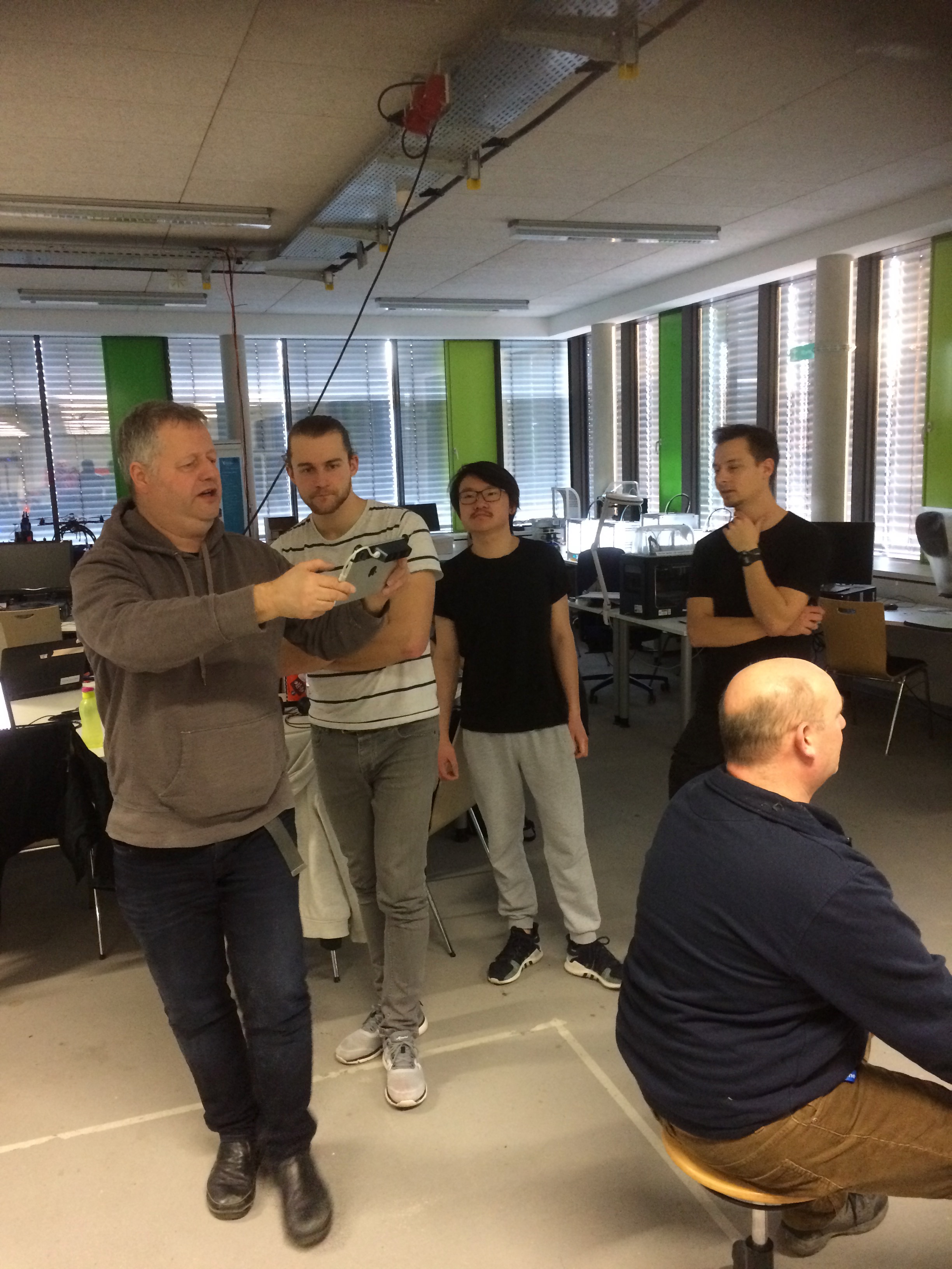
The method for scanning is simple. Modern software has come a long way since the days of yore when I had to make my own scanner using a laser pointer, linear motor and a webcam to scan a store mannequin (don't ask). The first step in the process involves attaching a stereo camera to the back of an iPad, then starting the software. Next one selects a scene by tipping the iPad until the colour changes to red and yellow on the screen. Then it's just a question of walking slowly around the model, rising and dipping to catch over- and underhangs, and stopping whenever the software needs to take a key frame, or loses the model. As long as the scene is relatively complex with large, slowly changing (with angle) geometries, the software can track the motion of the camera. With more difficult geometries, such as the race car frame below, the camera gets lost quickly.
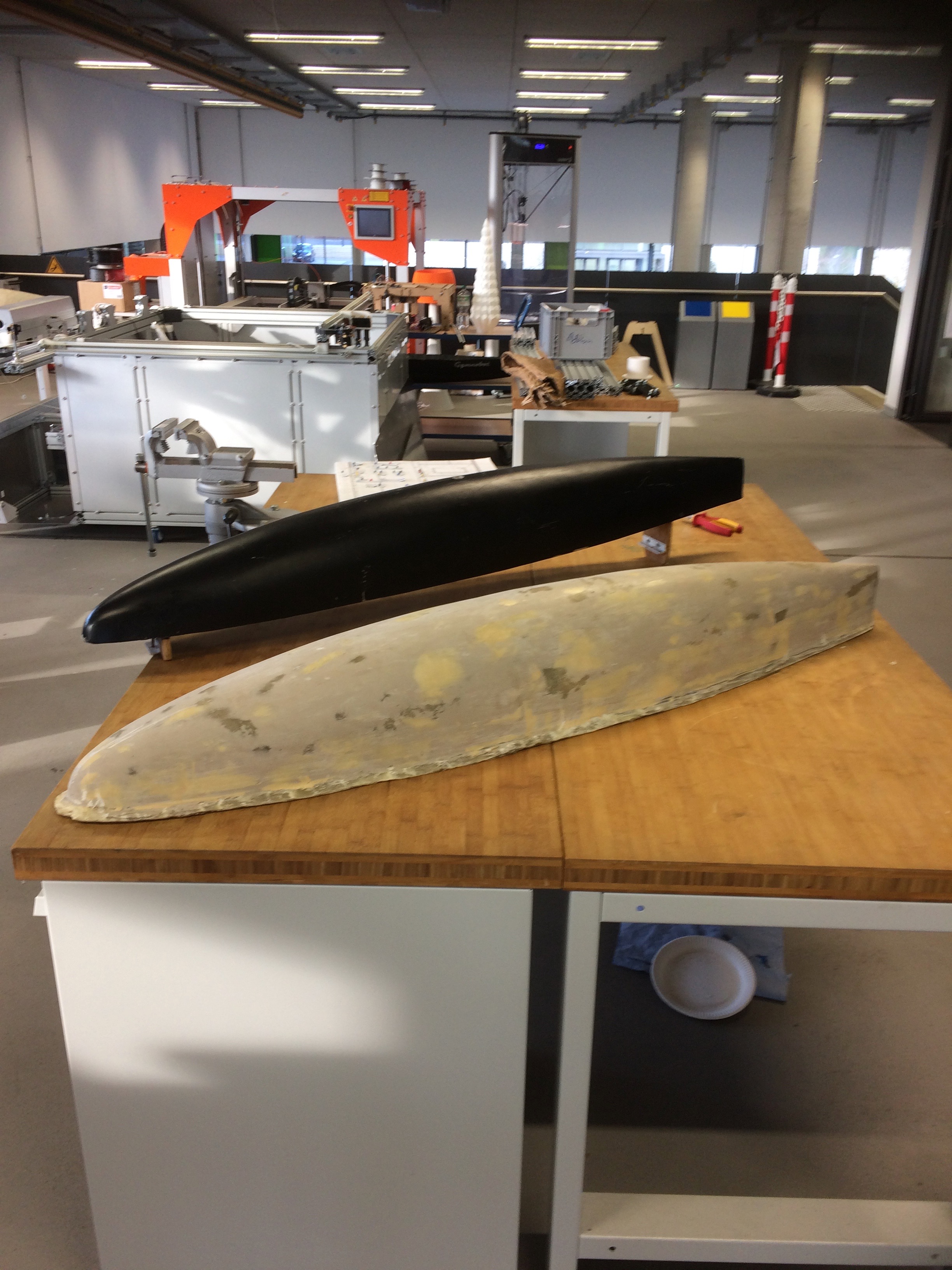
The first model I scanned was a simple closed shape: the mould of the hull of the existing Gymnobot robot submarine. Here it is in real life. The grey form in the foreground is the positive mould, while the black one in the background is the fibreglass top half of the hull.
After scanning, and without doing any post-processing, the following model is produced (the little object in the background is the edge of the vice on the table, which is visible in the photograph above.)
Spurred on by how easy that first scan was, I thought I'd try something more difficult. Our Formula Student team have had their chassis made, but the precision of the welding has not been verified yet. So here goes making a 3D scan of it as the first step in this quality control process.
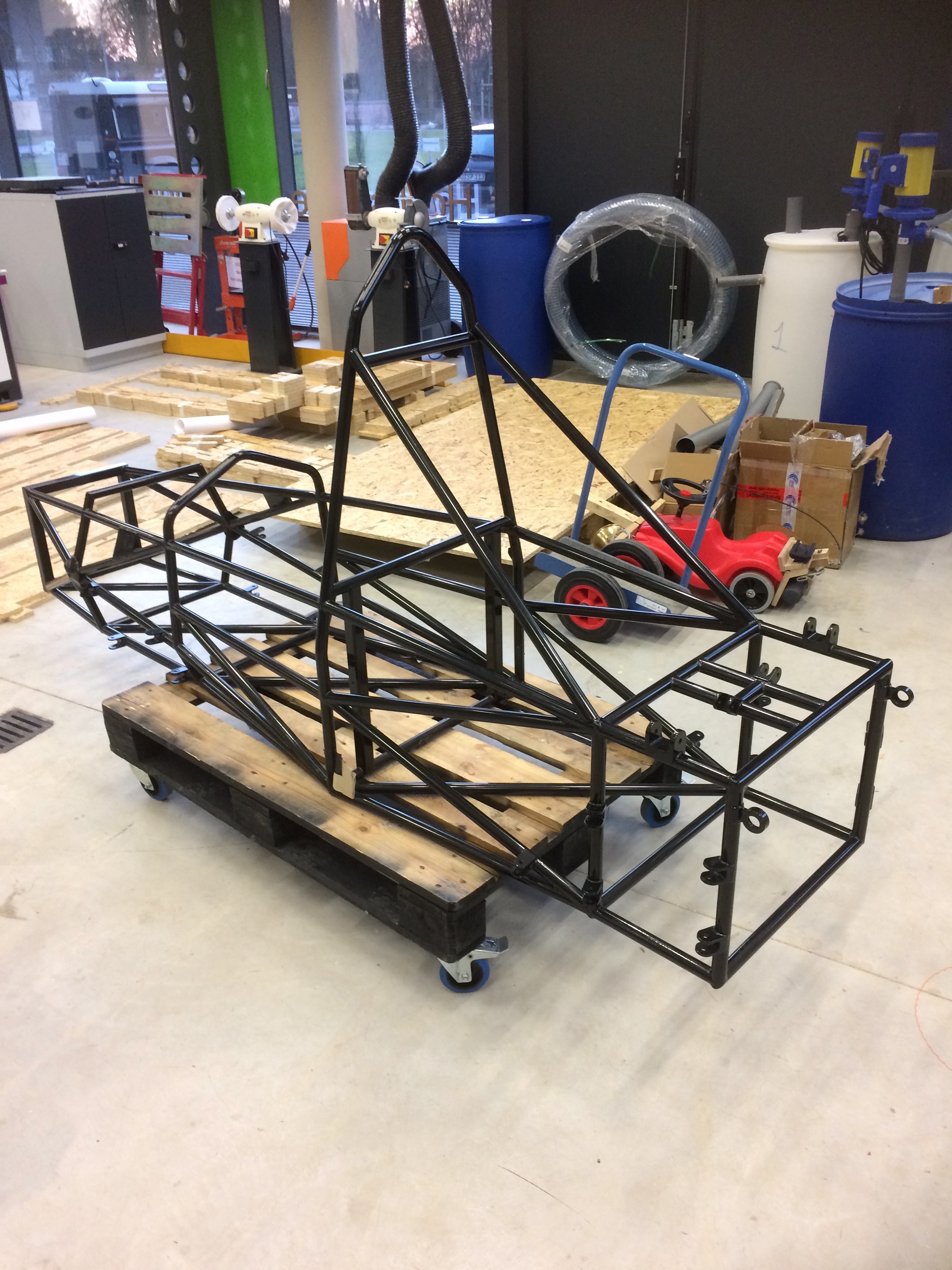
A first try at scanning this lovely, shiny, black frame was a total failure. The software failed even to recognise it. All of the other stuff around the car shows up in the scan, including the shiny blue steel tube on the little cart in the picture, but the car itself remains essentially invisible. The problem was therefore assumed to be the colour and glossy finish. To test whether this was indeed the problem, I covered elements of the frame with masking tape, then (to save tape) with blue paper towell.
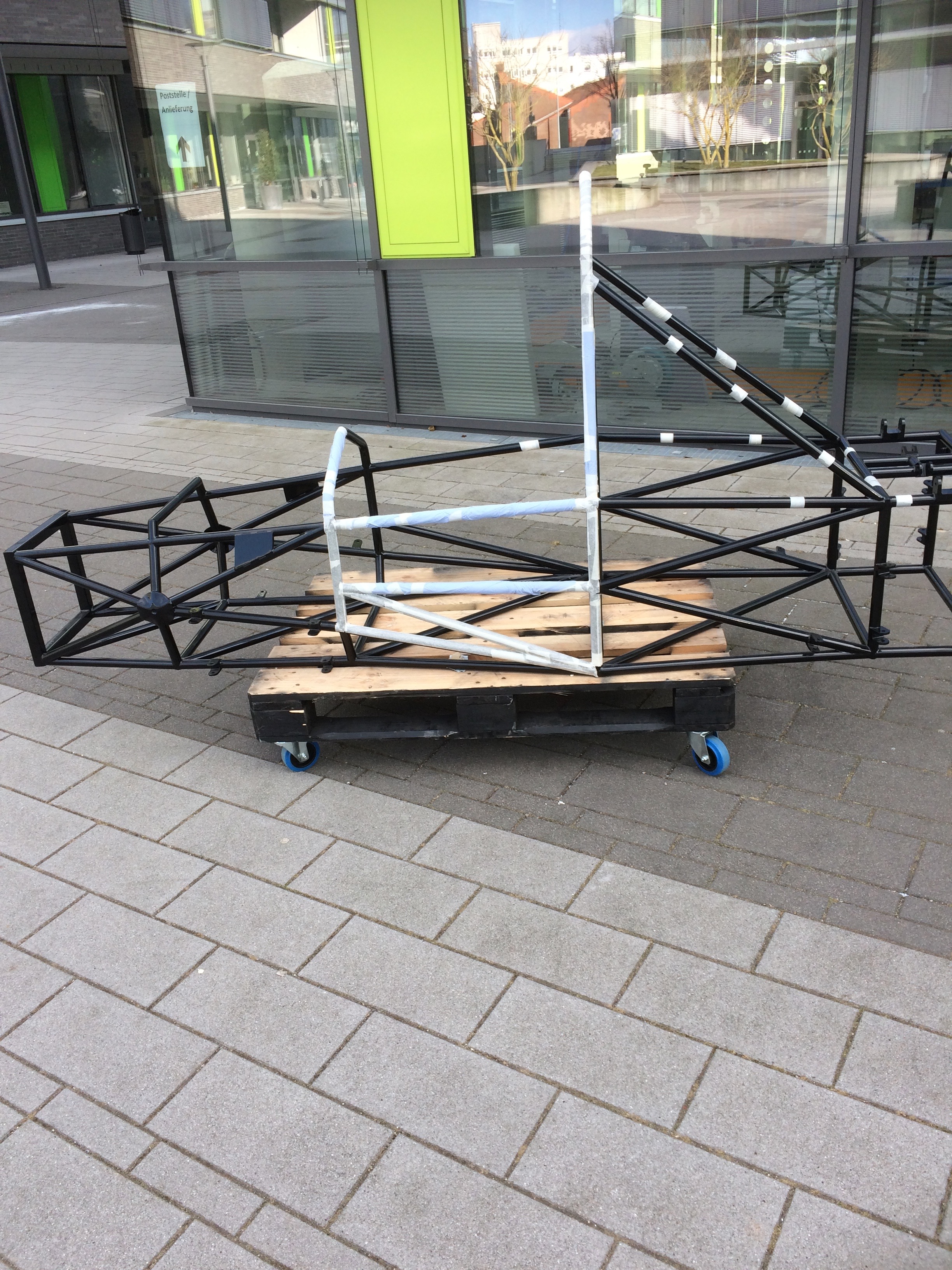
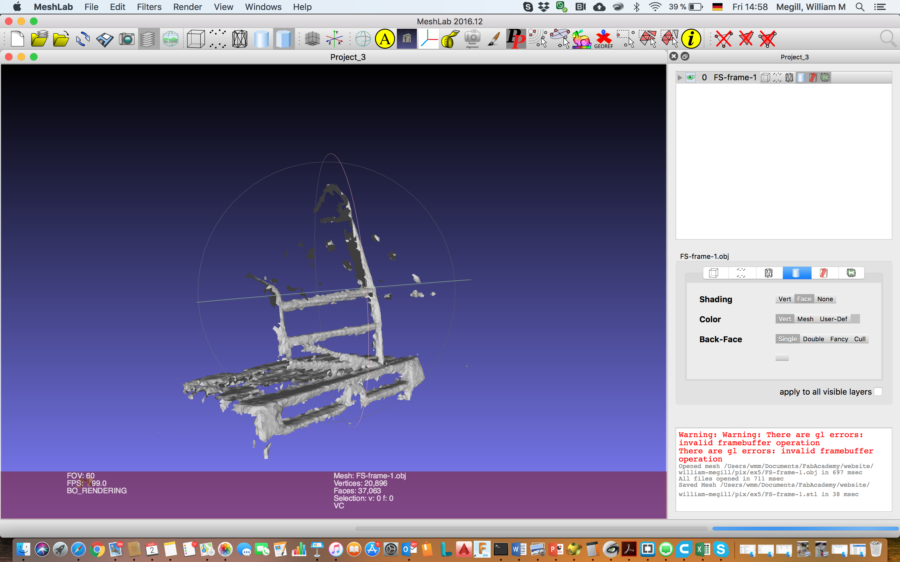
As shown in the canvas below, the scanner had a much easier time of it after this modification. The bars covered in blue paper are as obvious in the scan as the pallet on which the frame rests. The glossy black bars remain invisible.
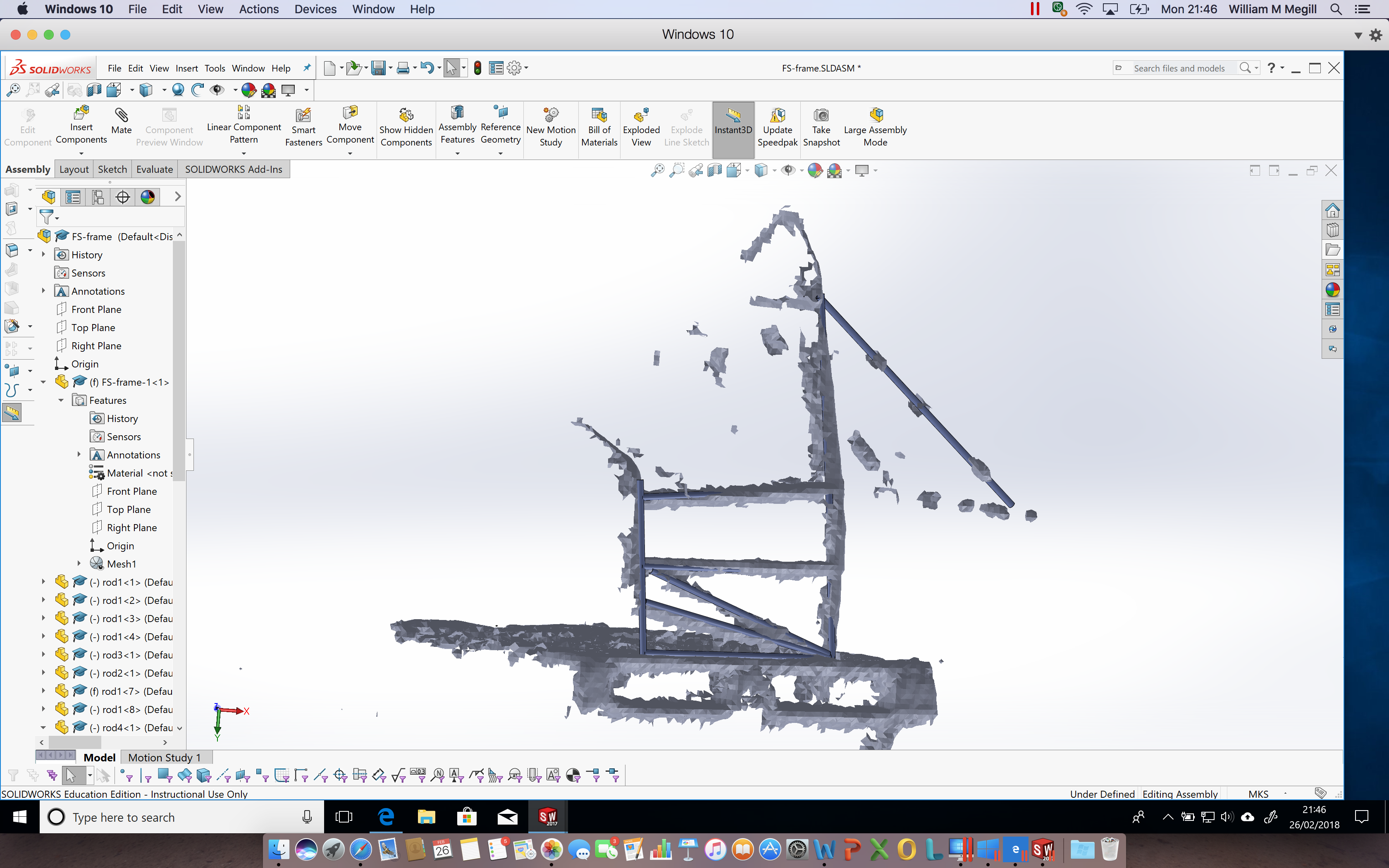
This scan is obviously not nearly precise enough to do much for the Formula Student team, but to start thinking about how they will approach the problem, I built a quick and dirty model of part of the frame in Solidworks and imported the scan as a part (having converted it from obj to stl using Meshlab as shown below).
The model is shown below in blue, poking through the scanned surface. Note the diagonal bar at the back of the car which lines up nicely through the splotches that correspond to the rings of masking tape wrapped around the bar of the real frame.
On Thursday, the team will have the chance to work with Kamp-Lintfort's high resolution scanner. They've promised to share the results with me. I'll report those when they're available. It will be interesting to see the improvements.
3D Printing, Revisited
I'm gearing up for a more involved 3D-printing job, back on the submarine. The team has had some aluminum casting work donated, to make some of the more complex elements of the submarine chassis. The objects will first be 3D-printed in full-size, and then we'll have them cast in sand to make the aluminum part.
In the design of the submarine, there is a sweeping helical frame (chassis) intended to represent the curving lines of a swan in flight (the university's newly selected mascot is a swan, drawn from the name of the castle - Schwanenburg - that dominates the city skyline). The part was straightforward to draw in SolidWorks by intersecting a spline curve with the teardrop shape of the hull.

The strands of the double helix (also deliberately chosen, to represent the DNA of our biomimetic submarine) meet in three places: the top of the bow (head), at the base of the cockpit (sternum) and at the top of the hull above the wings (sacrum). The complex forms of these junction parts was extracted from SolidWorks by cutting the helix with intersecting planes, then by tracing 3D curves through the severed helix strands, and finally by lofting circular sections along the fitted splines. Additional brackets were added to fasten the junction elements to the keel. The three resulting parts are shown below.
 |
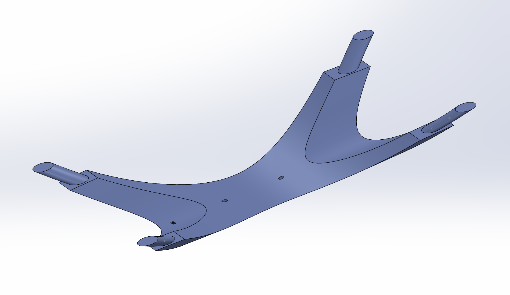 |
 |
We'll have a go at printing the parts on one of the large format 3D printers this week.