Tasks:
-Make something big
-Describe the forkflow( settign up the machine, using fixing, testing joints, adjusting feed and speed, depth of the cut etc.)
-Describe problems and how you fixed them.
The assignment for this week is to Make Something Big
The assigment requires a lot of time and money, so I have decided to make somethig useful. Our FabLab is building a GreenFab House, so my I have decided to make a Rocking Chair for it.
Fusion 360
I have used Fusion 360 to design a 3D modell of the chair
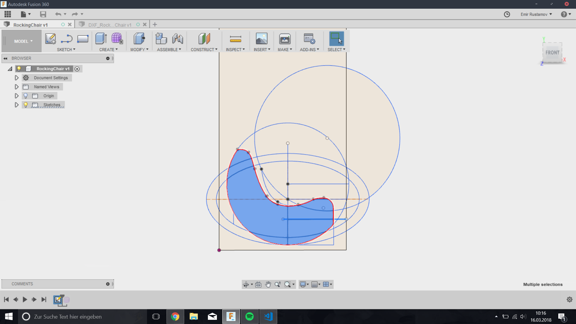
 Sketch
The Idea was to design a Rocking Chair as a Halfmoon. Here in this picture you cann see the how I started to design the Rocking Chair.
Sketch
The Idea was to design a Rocking Chair as a Halfmoon. Here in this picture you cann see the how I started to design the Rocking Chair.
 Joints
In my design I have used joints and keys, to kee the whole constuction together. To make this you have to consider the thikness of the material, in our case it was 18mm. I also didn't calculated any tolerance for the joints, so that they sit very tight.
Joints
In my design I have used joints and keys, to kee the whole constuction together. To make this you have to consider the thikness of the material, in our case it was 18mm. I also didn't calculated any tolerance for the joints, so that they sit very tight.
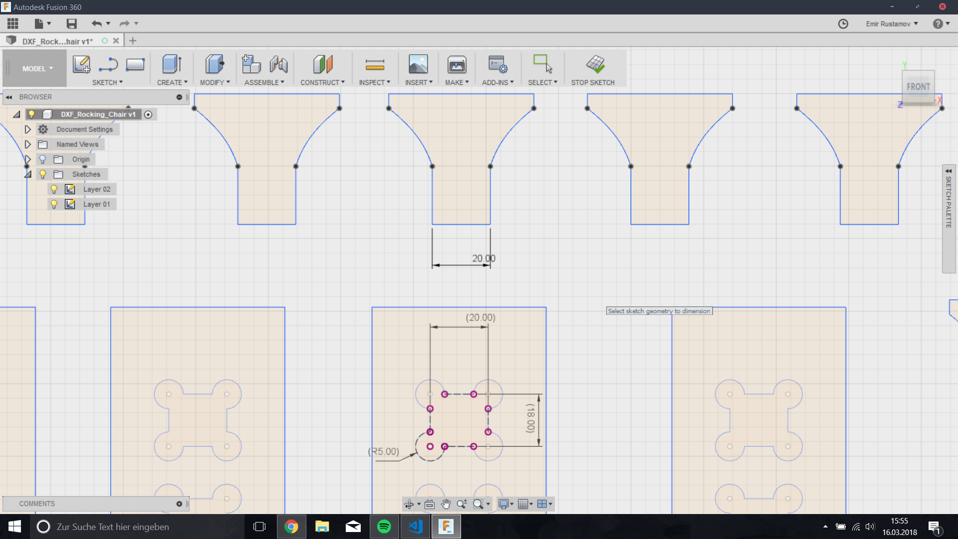
Tip: make some fillet to the joints.
It is also important to consider, that the tools is not able to make any shapr edges, if it makes a cut from the inside. So you have to make it this way:
-First you maka a Rectangle
Then you make circles at the edges of it.
I have used a tool with diameter of 6mm, So in my case I set the radius of the circles to 5mm. So The tool can path through and you have enough place for the edges.
Another way to do the joints is to use fillets, but it is a lot of work.
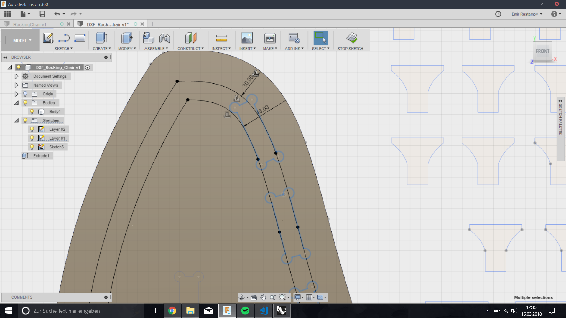
 Offset
So the next challenge was to align the rips. To do this I have made one offset of 30mm from the border and another 48mm. 48mm is because of the thickness of the material.
Offset
So the next challenge was to align the rips. To do this I have made one offset of 30mm from the border and another 48mm. 48mm is because of the thickness of the material.
 First finished sketch
Here how the whole parts looked like, after I have finished
First finished sketch
Here how the whole parts looked like, after I have finished
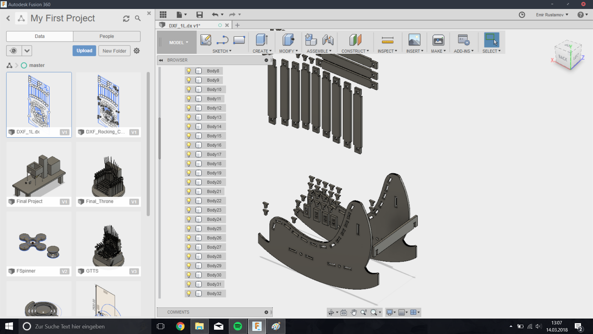
 Assambling
In this step, i have extruded all pieces with the height of 18mm and assambled together.
Assambling
In this step, i have extruded all pieces with the height of 18mm and assambled together.
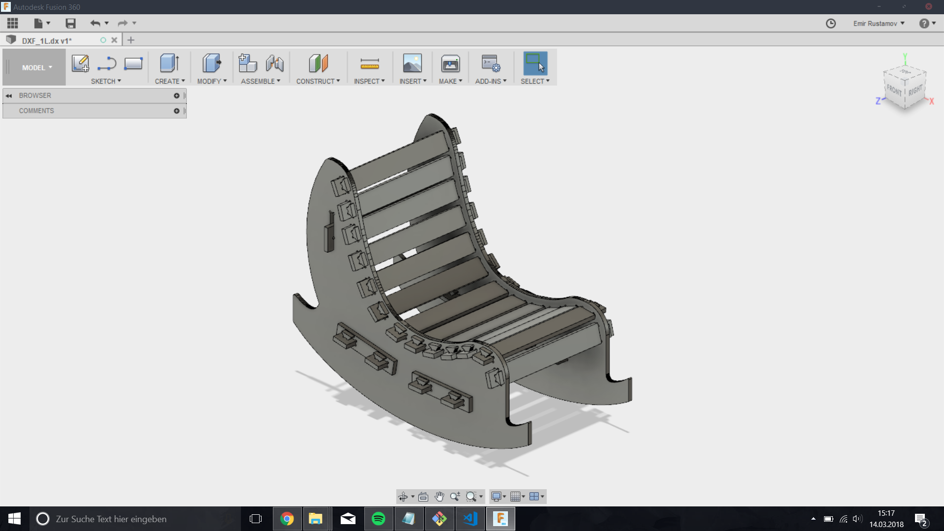
 Fusion 360
This is how it looked after the assembling.
Fusion 360
This is how it looked after the assembling.
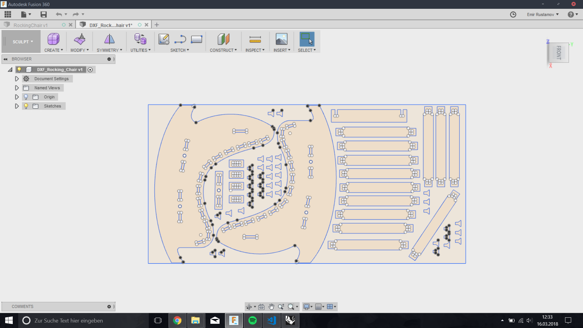
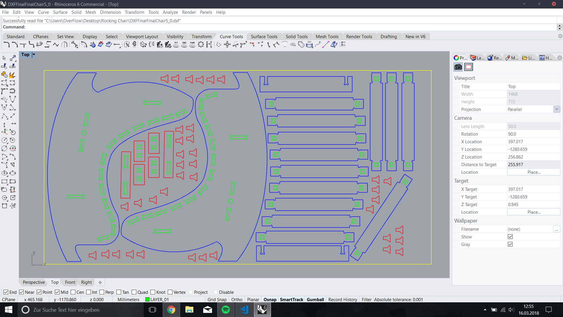
 Rhino
After i have exported everything as .dxf and opened in Rhino, I have modified it a bit, so this is ho the final dxf File looks like. In Rhino I have added 4 Layers.
Rhino
After i have exported everything as .dxf and opened in Rhino, I have modified it a bit, so this is ho the final dxf File looks like. In Rhino I have added 4 Layers.
-Green Layer is for the Inner Cut
-Red Layer is for the small parts, later I will leave some offset of 0.2 from the bed, so that they not move while cutting.
-Blue Layers is for the Outer Cut
-Yellow Layer will not be used in the Cutout, it is just a reference for the whole working space.
 Controlling Unit
Okay now we are ready to make a cut, so this is a controlling unit.
Controlling Unit
Okay now we are ready to make a cut, so this is a controlling unit.
.jpg) On the right side of it you can see a Main Switch.
On the right side of it you can see a Main Switch.
.jpg) First Step, is to turn on. I will document every single step, that will make me confidet to operate this machine.
First Step, is to turn on. I will document every single step, that will make me confidet to operate this machine.
.jpg) After we have turned it on, we have to press the 'Reset' button.
After we have turned it on, we have to press the 'Reset' button.
.jpg) The next step is to press the start button.
The next step is to press the start button.
.jpg) CNC4.01
Okay here is the programm we operate the CNC machine with.
CNC4.01
Okay here is the programm we operate the CNC machine with.
.jpg) Press Start
Press Start
.jpg) Okay, this i a CNC 4.01 window.
Okay, this i a CNC 4.01 window.
.jpg) Each time we start the machine, we have to home it. I it also written there.
Each time we start the machine, we have to home it. I it also written there.
.jpg) There a two posiblilities to home the machine, the first one: is with the CNC4.01 like in the picture below.
There a two posiblilities to home the machine, the first one: is with the CNC4.01 like in the picture below.
.jpg) The second one i with the ''. You can see a Homming button near the Finger.
The second one i with the ''. You can see a Homming button near the Finger.
.jpg) Okay after we have done this, we can put our piece of sheet on the bed.
Okay after we have done this, we can put our piece of sheet on the bed.
.jpg) Vacuum
Our machine has a vacuum on the bed. And we can adjust on which part of our bed shloud the vacuum go on.
Vacuum
Our machine has a vacuum on the bed. And we can adjust on which part of our bed shloud the vacuum go on.
.jpg) As you can see on the picture -> Vacuum is on, but the sheet is not aligned to the bed. So we try to swap the sides.
As you can see on the picture -> Vacuum is on, but the sheet is not aligned to the bed. So we try to swap the sides.
.jpg) Okay, now it is perfekt.
Okay, now it is perfekt.
.jpg) Tool
As I mentioned before, we are going to mill with 6mm tool, So we goo to the tool menu, and we can see which tool has 6mm.
Tool
As I mentioned before, we are going to mill with 6mm tool, So we goo to the tool menu, and we can see which tool has 6mm.
.jpg) Here we can see our tool.
Here we can see our tool.
.jpg) Now we have to pick up our tool, first go to the user menu.
Now we have to pick up our tool, first go to the user menu.
.jpg) Press 'Get Tool'
Press 'Get Tool'
.jpg) In the Interpreter Dialog you have to write the Tool number,that you need, in my case it is 3.
In the Interpreter Dialog you have to write the Tool number,that you need, in my case it is 3.
.jpg) After we change it, we will have the notification, about succesfull changing.
After we change it, we will have the notification, about succesfull changing.
.jpg) Zero Point
Okay now we have to set the Zero Point. It is the down right corner in our case. Wierd? yes, actually the view is rotated 90 deg to the left.
Zero Point
Okay now we have to set the Zero Point. It is the down right corner in our case. Wierd? yes, actually the view is rotated 90 deg to the left.
.jpg) Okay, here we have got a remote comtroller. It is really intuitive to use it. But, it has a safety button on the right side, that should be pressed if you want to controll the machine.
Okay, here we have got a remote comtroller. It is really intuitive to use it. But, it has a safety button on the right side, that should be pressed if you want to controll the machine.
.jpg) You see the button with the writing: 0.01/0.05/0.1/0.5/1/. This button changes step of the machine while operating it with the remote controller.
You see the button with the writing: 0.01/0.05/0.1/0.5/1/. This button changes step of the machine while operating it with the remote controller.
To adjust the speed, press the safety button and 1-2-3-4-5 times according to the unit. If youn press 6 times you return, to the normal movement speed.
.jpg) Okay, this it how it should be placed.
Okay, this it how it should be placed.
.jpg) In the CNC4.01 we have to press to the X and Y button to set the xy Zero position.
In the CNC4.01 we have to press to the X and Y button to set the xy Zero position.
.jpg) Sensor
Now we have to set the Zero point of the Z axes, it could be different, for example: according to the bed. Sensor is on the head of the machine.
Sensor
Now we have to set the Zero point of the Z axes, it could be different, for example: according to the bed. Sensor is on the head of the machine.
.jpg) To detect zero Point of the Z axies, we have to put our sensor on the bed and the drill over it. Imporant, we need 2 persons to detect it.
To detect zero Point of the Z axies, we have to put our sensor on the bed and the drill over it. Imporant, we need 2 persons to detect it.
.jpg) So the second person should press the Detection Button 'F2'.
So the second person should press the Detection Button 'F2'.
.jpg) Work
How we have to load a work, to do this, we have to the Program menu at the top bar. An than click Load.
Work
How we have to load a work, to do this, we have to the Program menu at the top bar. An than click Load.
.jpg) Okay after we have loaded the .dxf File we have to align it to the Lower Left corner, like in the picture. You can also see if your piece is not aligned. You can see it on the corners of the Working place.
Okay after we have loaded the .dxf File we have to align it to the Lower Left corner, like in the picture. You can also see if your piece is not aligned. You can see it on the corners of the Working place.
.jpg) This is how it looks after the alignment.
This is how it looks after the alignment.
.jpg) Layers
Okay now at the top right you can see DXF layers that you added in Rhino for example. You can turn it on and of for your needs. In my case I need to make inner cut outs, so i will activate only this layer.
Layers
Okay now at the top right you can see DXF layers that you added in Rhino for example. You can turn it on and of for your needs. In my case I need to make inner cut outs, so i will activate only this layer.
.jpg) Okay at top we have several functions:
Okay at top we have several functions:
-with Drill we make holes
-Engrave: if we choose Engrave we have to consider 1 thing. The Drill is going to follow the lines in the dxf files, that means that we have to calculate raduis of the tool to the both sides.
-Pocket: Pocket makes it from the inside, so we have to consider, that it is not able to make any angles.
-Offset: Is what wil will use for our job. here you can define if it schould go Inside our ouside way of the lines.
.jpg) Settings
Okay now I will explay the setting, that we have to set.
Settings
Okay now I will explay the setting, that we have to set.
.jpg)
Safe-Z: 30mm //Here we have to count the height of the material, that we are going to use, in my case it is 18mm. +approx . 40% of it
Start-Z: 30mm //Height of the material, in my case 18mm + tolerance of 0.5 mm
Final-Z: -0.200mm //Zero-Poit of the z axies 0.0 -0.200mm tolerance
Z-Increment: 2.4 // Z axies stepdown
FeedRate: 2000 // Movement Speed
PlungeRate: 800 // Stepdown Speed
SpindleSpeed: 18000 // It is rpm(Rotation per min.)
SpindleDirection: CW // you can schoose between clockwise or counterclockwise
LaserMode: // not needed
ToolNumber: 3 // we have to write the tool number we have choosen before.
ToolDiameter: 6mm // again Depends on the tool we have choosen before.
Method: Inside CCW // so for this layer I should be  Inside CCW, because it is an Inner Cut for the Joints
Bridges: // no need for it
After we have set all proper settings, we have to calculate a toolpath.
If we Zoom In we can see that the tool is going inside.
.jpg) Now we have to generate a GCode and save it on PC. Don't save it on removeable Flash disk -> if someone remove it while the work, you will loose everything.
Now we have to generate a GCode and save it on PC. Don't save it on removeable Flash disk -> if someone remove it while the work, you will loose everything.
.jpg) DustCover
Okay, now we have to open the operate menu and Activate a DustCover.
DustCover
Okay, now we have to open the operate menu and Activate a DustCover.
.jpg) Here how it looks like
Here how it looks like
.jpg) Okay now we have to be sure, that this Dust Gate is opened(FabLab specific)
Okay now we have to be sure, that this Dust Gate is opened(FabLab specific)
.jpg) We have 2 Dust Gates, with the right swich you control the Dust Gate for the CNC machine(again FabLab Specific)
We have 2 Dust Gates, with the right swich you control the Dust Gate for the CNC machine(again FabLab Specific)
.jpg) Now turn of the Dust Machine.
Now turn of the Dust Machine.
.jpg) Run
Okay, now go back with in CNC4.01.
Run
Okay, now go back with in CNC4.01.
.jpg) Press Auto Now you can launch a GCode.
Press Auto Now you can launch a GCode.
.jpg) Press start, to lauch a job.
Press start, to lauch a job.
.jpg) It Works
It Works
.jpg) Small Parts
Okay these are the setting For the Small parts, like keys. Here I have only changed the Final-Z: 0.200, so that the pieces dn fly away. And the Method : outside CW. In the Last Layer I had a Final-Z: 0 and Method: outside CW.
Small Parts
Okay these are the setting For the Small parts, like keys. Here I have only changed the Final-Z: 0.200, so that the pieces dn fly away. And the Method : outside CW. In the Last Layer I had a Final-Z: 0 and Method: outside CW.
.jpg) Here you can see the outside Path.
Here you can see the outside Path.
.jpg) OutSide Cut
OutSide Cut
.jpg) Assambling
Assambling
.jpg) Testing
Testing
.jpg)
.jpg)
.jpg) Downloads
RockingChair.f3d
FinalRocking.dxf
Downloads
RockingChair.f3d
FinalRocking.dxf