Tasks
-Select and use software for circuit board design.
-Demonstrate workflows used in circuit board design.
-Redraw the echo hello-world board, add (at least) a button and LED (with current-limiting resistor), check the design rules, and make it.
Eagle
The Software I am going to use for this assignment is Eagle Eagle (Easily Applicable Graphical Layout Editor) application with schematic capture, printed circuit board (PCB) layout, auto-router and computer-aided manufacturing (CAM) features.
ATtiny 44The microcontroller that we have to work with is ATtiny 44. We have already used it 1 Week ago for the FabISPLibraryIn order to work properly, have to download and use special Libraries. Eagle has a a huge amount of build in libraries that we can use. I my case, I have used Fab Academy Libraries. After you forward the link, you have to choose, the program you are working with and than download the proper Library.Eagle SchematicEagle has two windows that are used simultaneously to design a board:
-Schematic (.sch) - logical components
-Board Layout (.brd) for the actual board that we mill
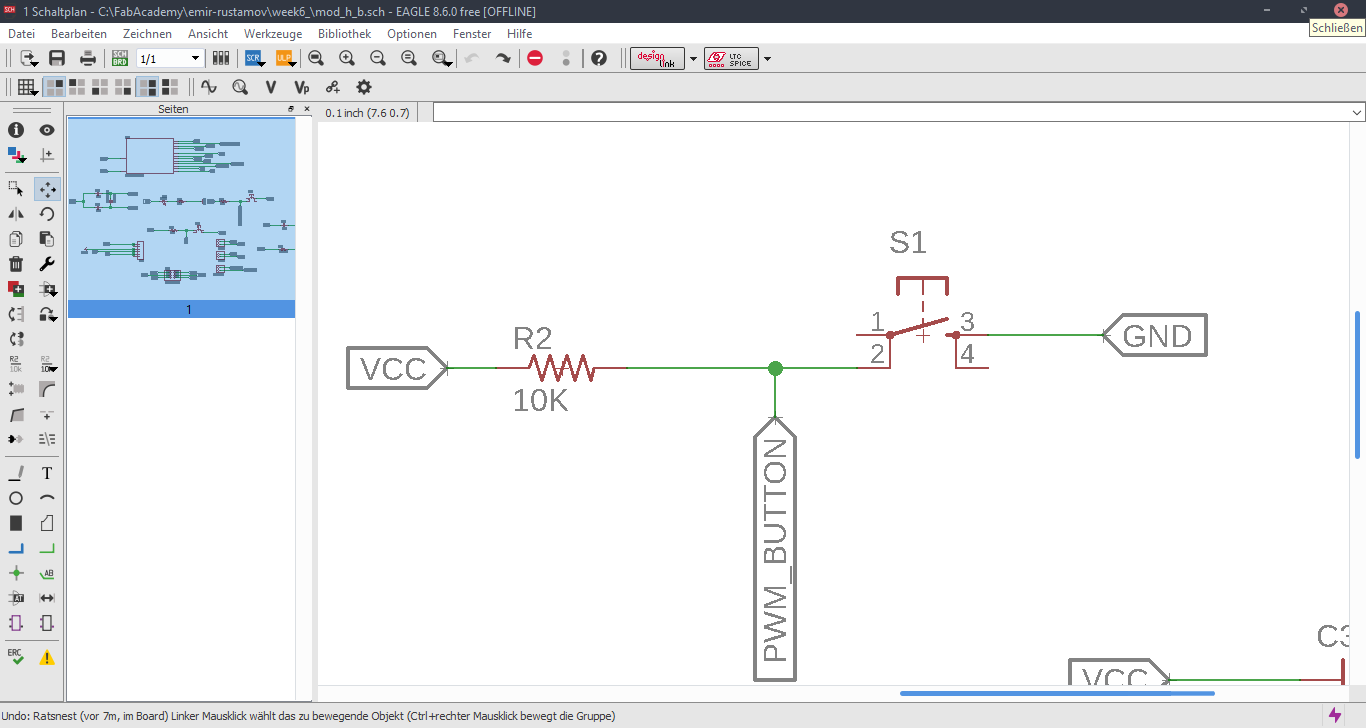
Now we are at the Schematic window. Okay first we have to add the needed Library, to do this first click to the Add button, like in the picture below.Now Open the Bibliothek Manager and add the libraly, you have downlaoded before.Attiny44Now click to the same Add button, that I mentioned before and you will be able to find a fab library, that you have included, with the previous step. Here you can find all needed logical components, that you need. For example ATTiny44First stepsOne nice this, that i like about the Eagle is that the pins have names, and you can easily figure out which pins you have to use for Power, GND and programming, the Crystal pins are also highlighted there. To add Labels and connections you have buttons at the left menu side of the window. In order to change the values and names of the components, you have to zoom in to the placed component and right-click on it.Okay this is how my logical pin layot looks like.CrystalI have used 20 Mhz Crystal, and for this specific crystal we need 8 pF Capasitors connected to the ground.ButtonI have added a button, the buttons requires 10k resistors to limit the curren tflow.Reset ButtonI have also added a reset button.LEDHere we have a LED it requires 499 Ohm resistor again the same, to limit the current flow.According to the DC Forward Current of the datasheet I have to use 499 ResistorPinsThese are FTDI and AVRISP pinsPower GND Analog PinsI have also mentioned, that we have got two analog pins, that we can use later, so I have made pins for them. I have also added 0Ohm resistor as Jumper, but I have done after I have placed all my components in boardlayout. Okay after we have have finished with the logical connections, we have to play all aour componens in a proper way in Board Layout. to switch the window click circled to the button above.RoutesTo create the routes, you have got an icon in the bottom-left corner. You can also specify th thickness of the routes above. In my case I have use 0.12 mm.GroundI some cases you can skip the connections of the GND. Make the whole unused space of the board to the GND. To do this, we have first to create a polygon. You can also find it in the bottom-left corner.Fill the GNDFill the unused spaces, we have to click RatsnestProperties of the GNDThan zoom in to the border of the GND, right-click on it and click Properties.IsolationIn the Properties we have to change the isolation. Isolation, is the space, between GND and Traces or components. It is recomended to change it according to the width of the routes.0 Ohm JumperOkay, here you can clearly see why I have used the 0 Ohm Jumper. After I have placed and connected all components. I had an issue with the Ground. The Gounds were not connected. So i have added the 0 Ohm resistor as a solution.ExportNow we have to export out Board Layout as an image.Export SettingsThese are recomended exporting settings.Exporting SettingsNow you have to crop the unnecessary borders from your image. It should look something like this.Now you have to cut out the engraving space sout and save the image for the cutout(Roland).MillingI will not explain how, we have to create a GCode out of the images. It is explained here.After MillingAfter SolderingProgrammingOkay now I am going to program my Board with FabISPOkay first of all we have to connect our Board in a proper way.
-MOSI to -MOSI
-MISO to -MISO
-SCK to -SCK
-RESET to -RESET
-GND to -GND
To power my HelloBoard I have used the FTDI cable.
Arduino IDEOkay after we conneted everything in a proper way, we have to open ArduinoISP in Arduino IDESelect everything in a proper way. And burn boot loader.
*If you are programmint Attiny 44 at first time, you may have to install the needed library. to do this open this Link and follow the instructions.TextNow we can load a program to our board. I have loaded a Blink example for the testing purposes.We have to load a program to our board using programmer.DoneDownloadsfab.lbrSchematicBoard