Electronical Production - FabISP
One part of the assignment for this week is to reproduce a PCB Board -> FabISP.
PCB stands for Printed Circuit Board. PCB mechanically supports and electrically connects electronic components or electrical components using conductive tracks, pads and other features. In most cases the board is something soild covered with the sheet of copper, often 0.3 mm that we etch or mill, leaving pads and tracks where we want to place our electronic components and the connections between them.
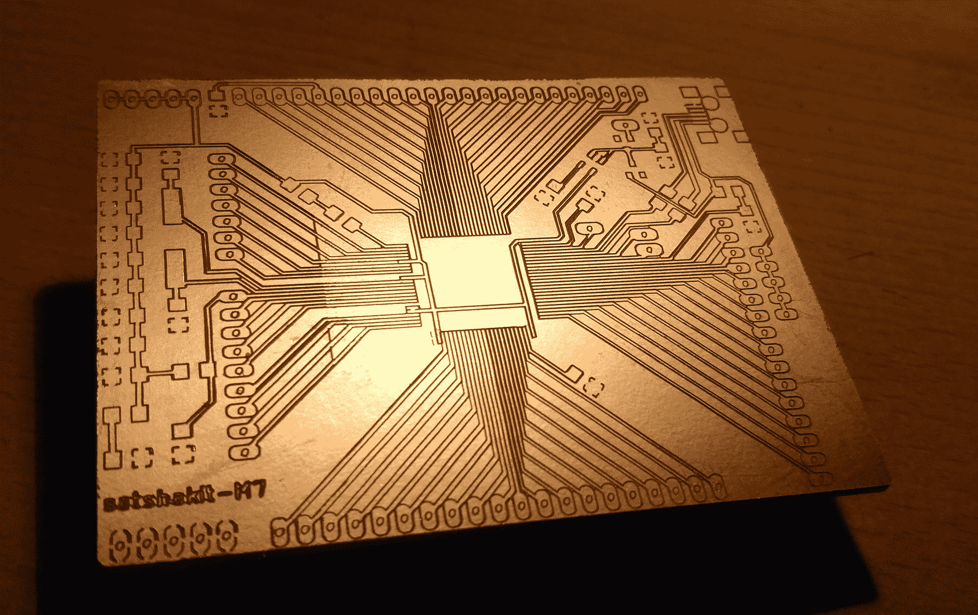
Example picture taken from:
satshakit-M7
 Roland MDX-40A
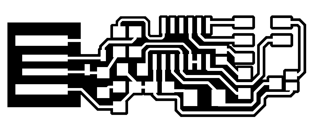
To mill our PCB boards have Roland MDX-40A. In order to work with this machine we need a GCode. To generate a GCode we had 2 PNG files, one for traces and another for the frame, and GCode generator. To generate a GCode from the PNG's we had used Fabmodules
 FabModules
Okay now we are at Fabmodules. First we have to select PNG as an input format acconding to the fileformat that we have. Then the Roland Mill as an outout device. With the next step we choose PCB Traces (1/64) as process. Last but not least: we have to choose the MDX-40 machine. Okay at the right side of the screen you will see a menu, where you can set some settings. With the next step I will show you the (OPT) settings, that I have used.
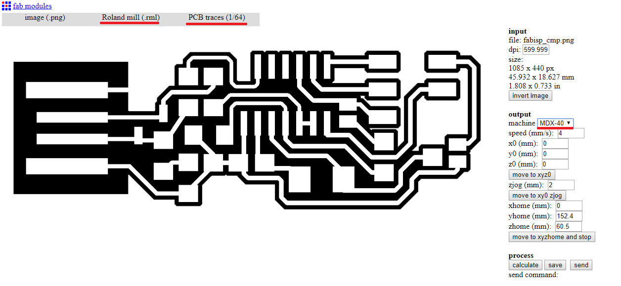 Settings
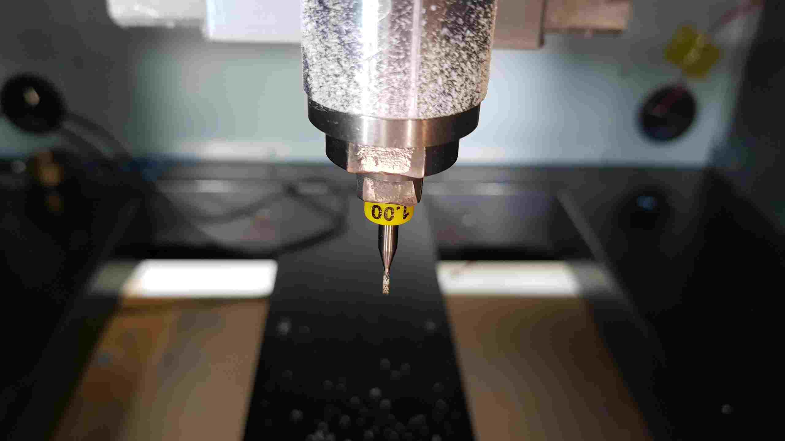
Okay these are recomended settings, that we have to use. X and Y should be 0, because we define Zero position later. In cutout, we have it by 1.9, in oder to cut the board. Jog height, is the height for the jumps between. Cut depth is 0.0, we set it manually. By Engraving we use 0.2 mm tools and by cutout 1.00 mm. Number of offsets, means how often the curves should be repeated. By -1 it will remove everything except the pads and traces.
Engraving:
- X0 0
- Y0 0
- jog height 5mm
- cut depth 0.0
- tool diameter 0.2mm
- offset overlap 55%


Cutout:
- X0 0
- Y0 0
- cut speed 1mm
- jog height 5mm
- cut depth 1.9mm
- tool diameter 1mm
- number of offsets 1
VPanel
Now we are at the laptop, that is connected to the Roland.
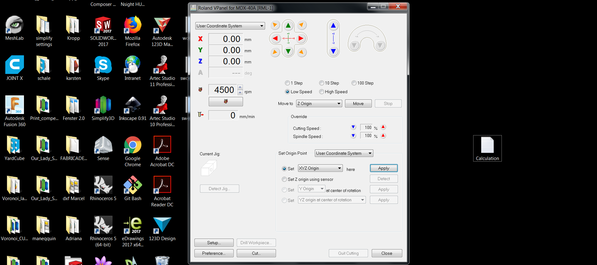
Here he have to start the Programm 'VPanel' -> the machine should be on, otherwise the programm will not recognize a machine. VPanel is the GCode output programm for the Roland MDX-4A.
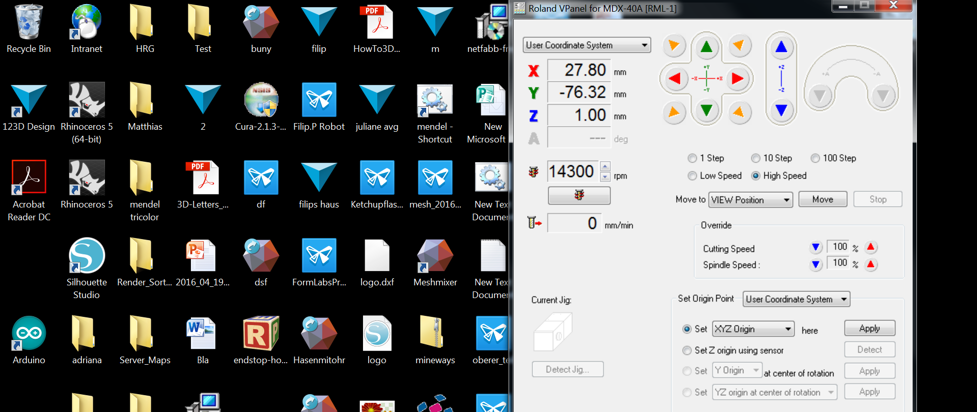 With the Arrows, that you see in the picture you can set focus of the machine. The focus should be set relative to the 0 Point in Fabmodule. The Mill should barely touch(scratch) the surface oth the Working space. After you have set you focus, just choose: Set XYZ Origin Point under 'Set Origin Point' an click 'apply' button.
You X,Y,Z values should be '0'.
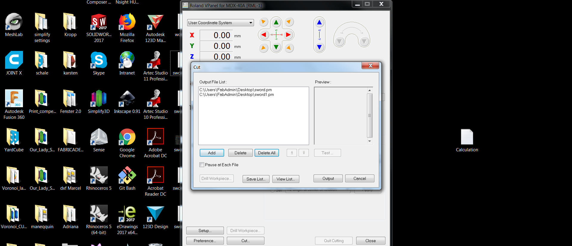
 Now just click 'Cut' button. Here you can load your binary codes.But be sure, that there is no other codes.
 FabISP
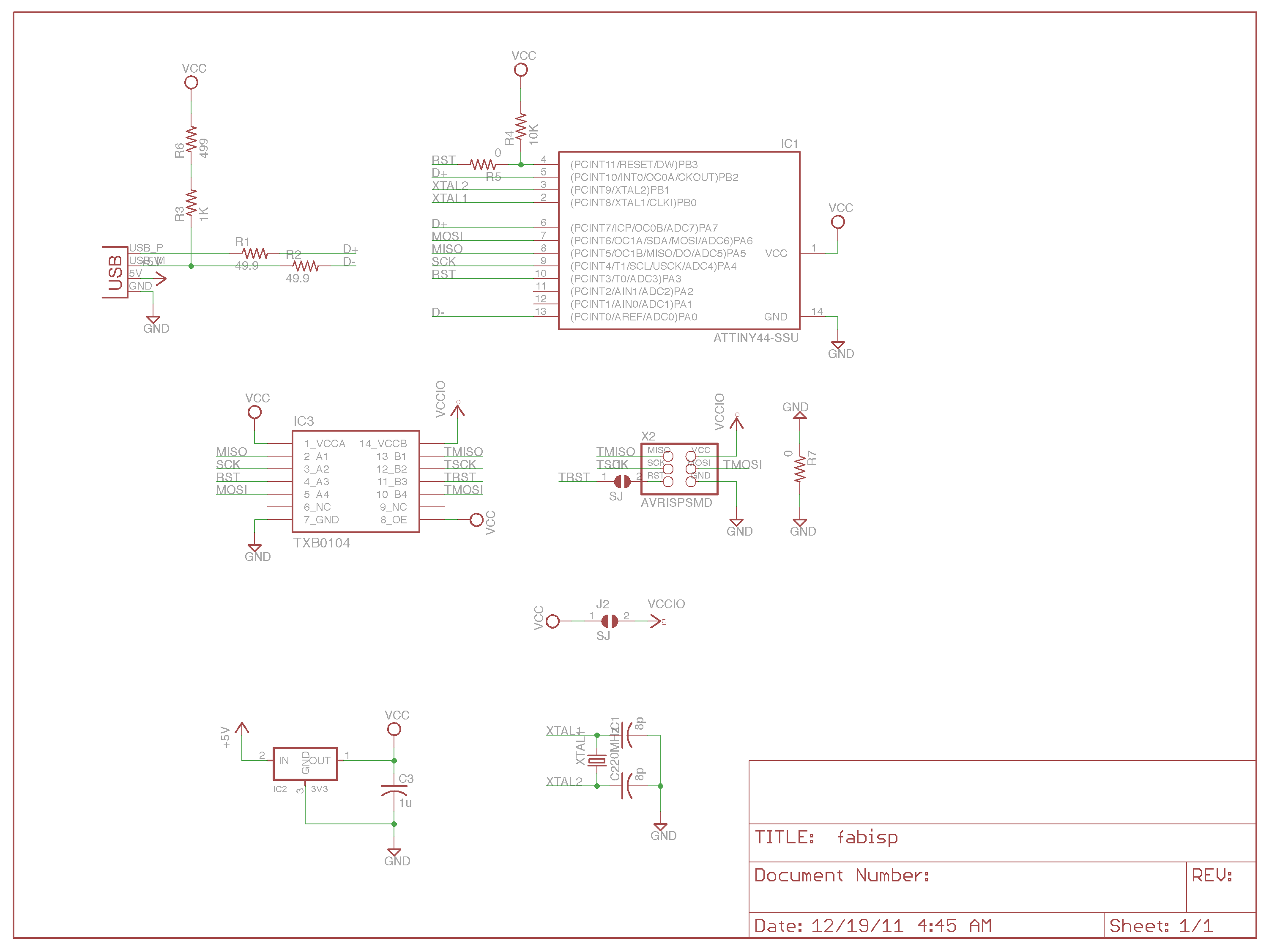
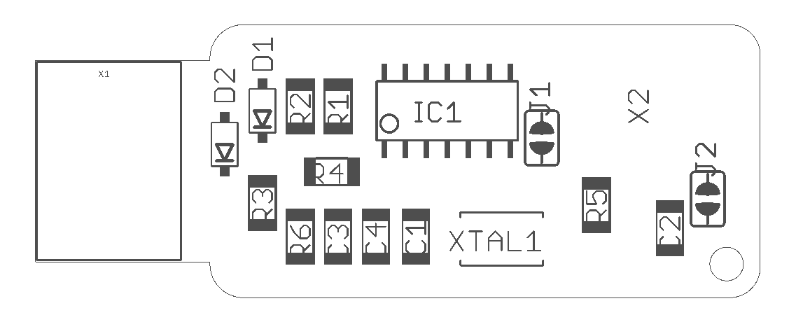
Here ist the schematic and the pinout of the FabISP
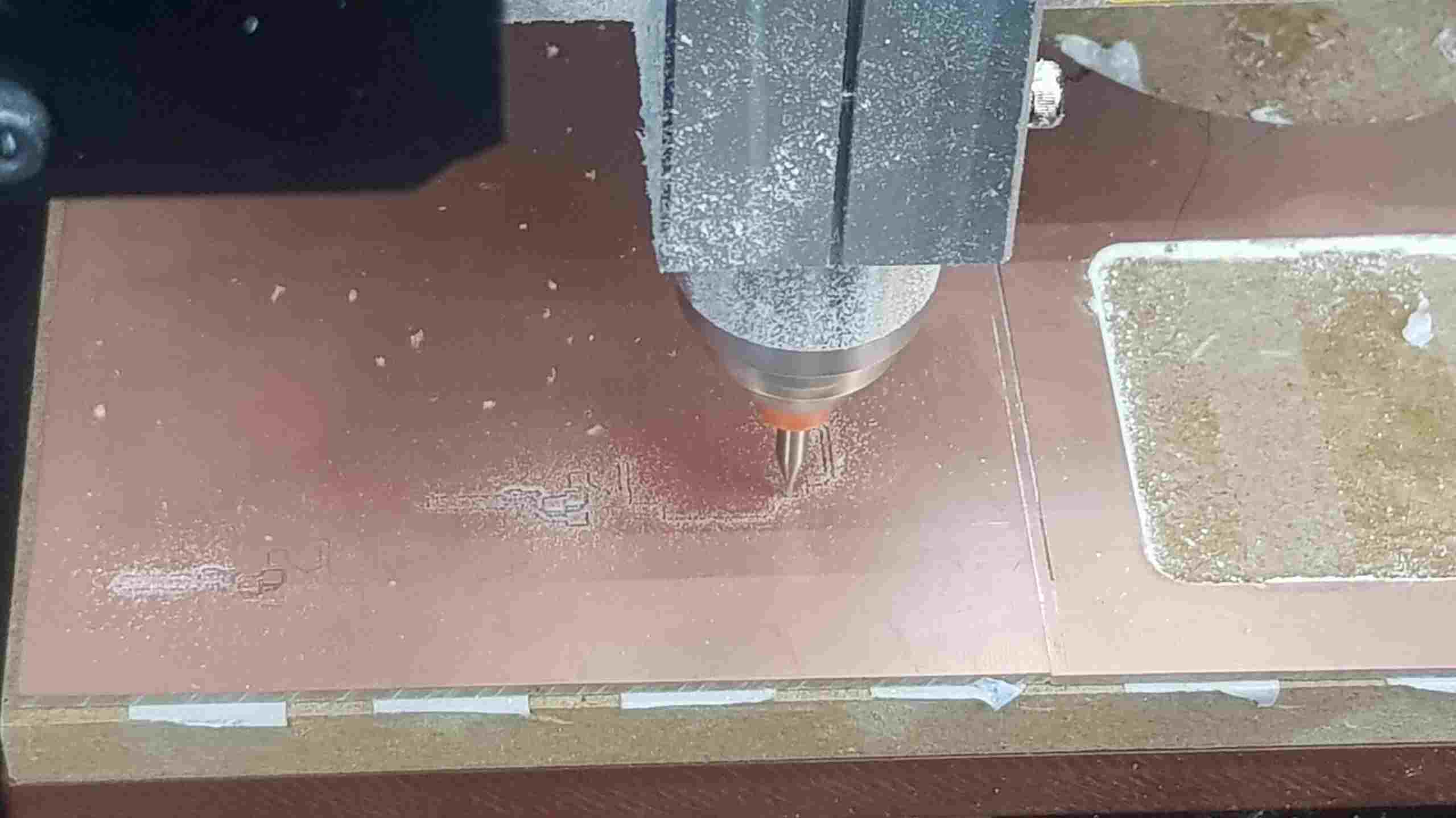
 Here we can see the beginning of the milling process.

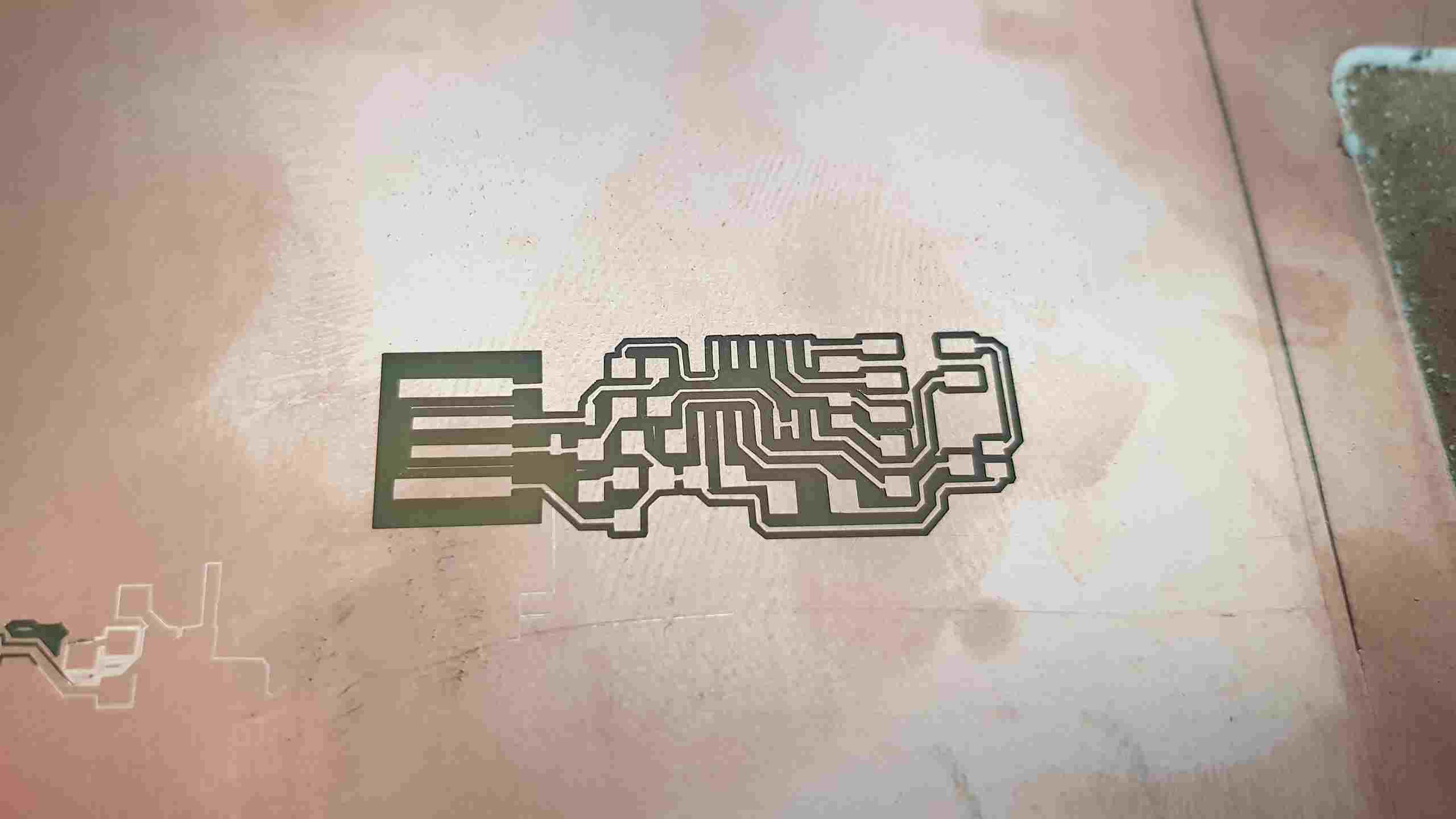 After we have milled the inside part, we have to change the tool to 1 mm in dm and lauch the cutout.
 Soldering process
 FabISP
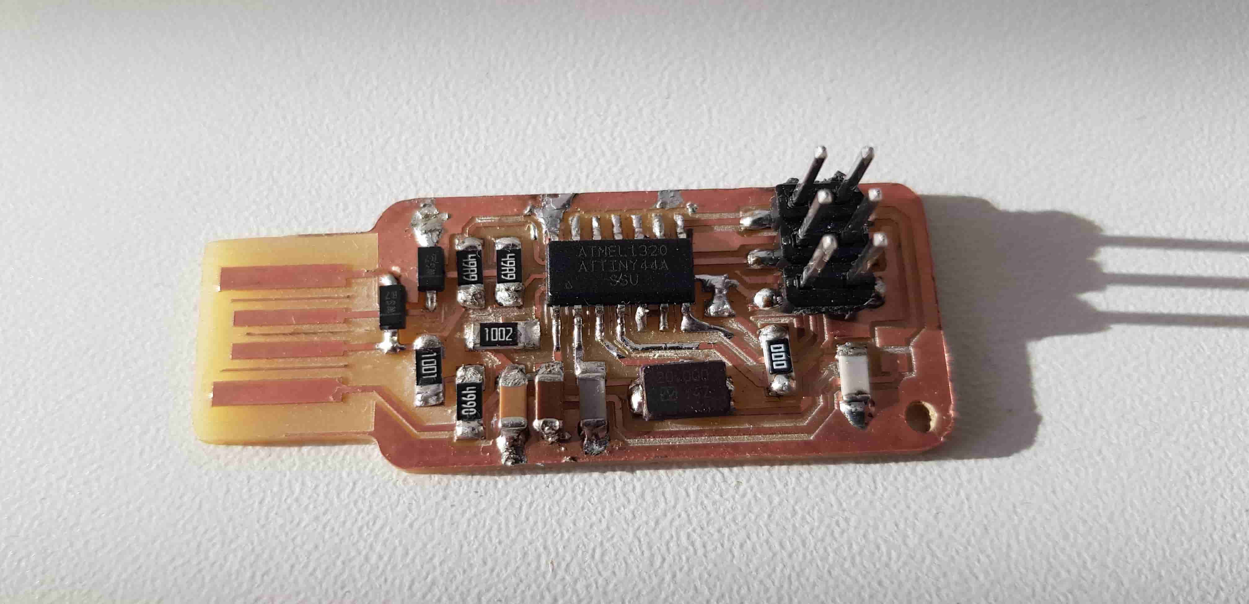
This is how my FabISP looks like after Soldering. Now we have to programm it. Don't forget to solder the jumper.
 Connection
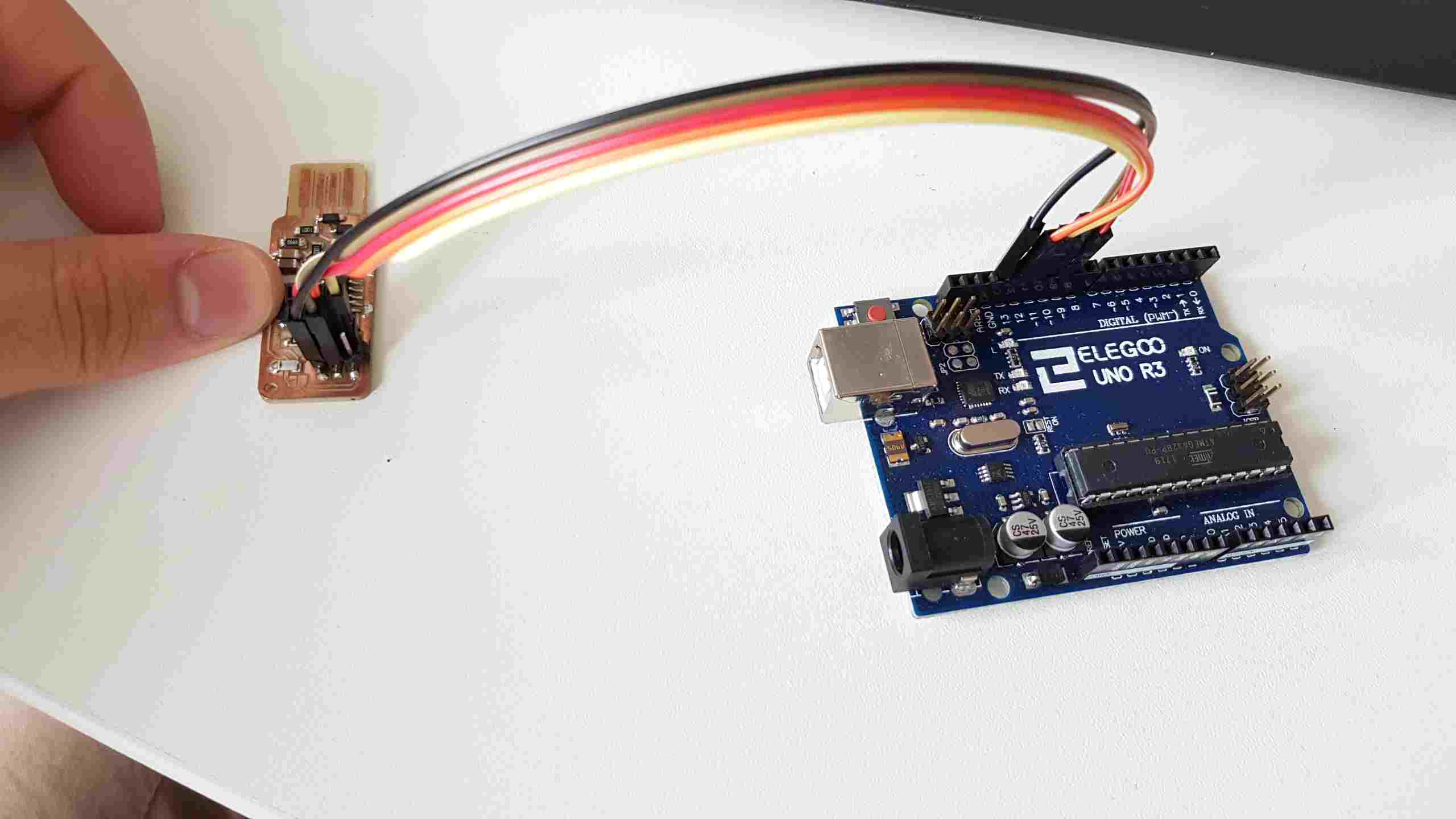
First connect your FabISP this way, and make sure that Arduino, has ISP programmed on it.

 Programming FabISP
I have extra installed UbuntuGnome on my PC for it, to be sure that there would not be any problems while recognizing FabISP.
Okay, First Open a termial and type:
sudo apt-get install flex byacc bison gcc libusb-dev avrdude
Then type:
sudo apt-get install gcc-avr
- type "y" when asked to do so by your system
Then type:
sudo apt-get install avr-libc
Then type (may already be installed):
sudo apt-get install libc6-dev
Move to the working directory, in my case Dektop.
cd ~/Desktop
Download the firmware from the Fab Academy Electronics Production page.
wget http://academy.cba.mit.edu/classes/embedded_programming/firmware.zip
Unzip the firmware.zip directory (the directory will be "firmware.zip" if you downloaded the earlier version):
unzip firmware.zip
Move into the newly created firmware directory on your desktop
cd ~/Desktop/firmware
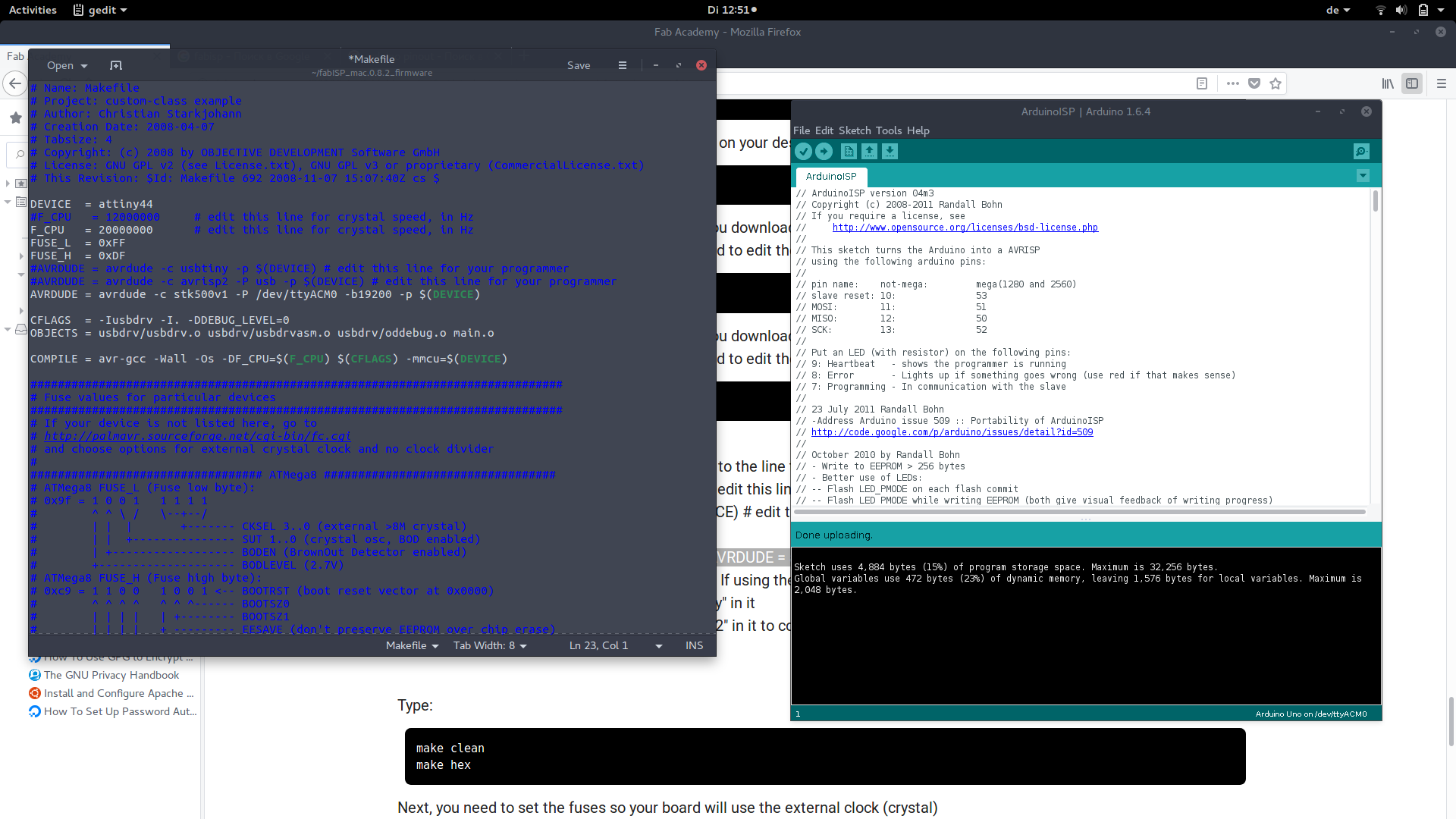
The Makefile is in the firmware directory that you downloaded. The Makefile is set up to work with the AVRISP2 by default. If you are using another programmer, you will need to edit the Makefile. In my case, I have to edit it. Use gedit Makefile to do so.
nano Makefile
The Makefile is in the firmware directory that you downloaded. The Makefile is set up to work with the AVRISP2 by default. If you are using another programmer, you will need to edit the Makefile. In my case, I have to edit it. Use gedit Makefile to do so.
gedit Makefile
Make Changes - All OS:
A window will open containing the Makefile. Go to the line that says:
#AVRDUDE = avrdude -c usbtiny -p $(DEVICE) # edit this line for your programmer
AVRDUDE = avrdude -c avrisp2 -P usb -p $(DEVICE) # edit this line for your programmer
In my case i had to replace the lie above with:
AVRDUDE = avrdude -c stk500v1 -P /dev/ttyACM0 -b19200 -p $(DEVICE)
hint: /dev/ttyACM0 -> where your Arduino conneted.
- If using the USBtiny programmer or another FabISP
- Remove the "#" in front of the line with "usbtiny" in it
- Add a "#" to beginning the line with the "avrisp2" in it to comment it out.
- save the Makefile
 Type:
Type:
make clean
make hex
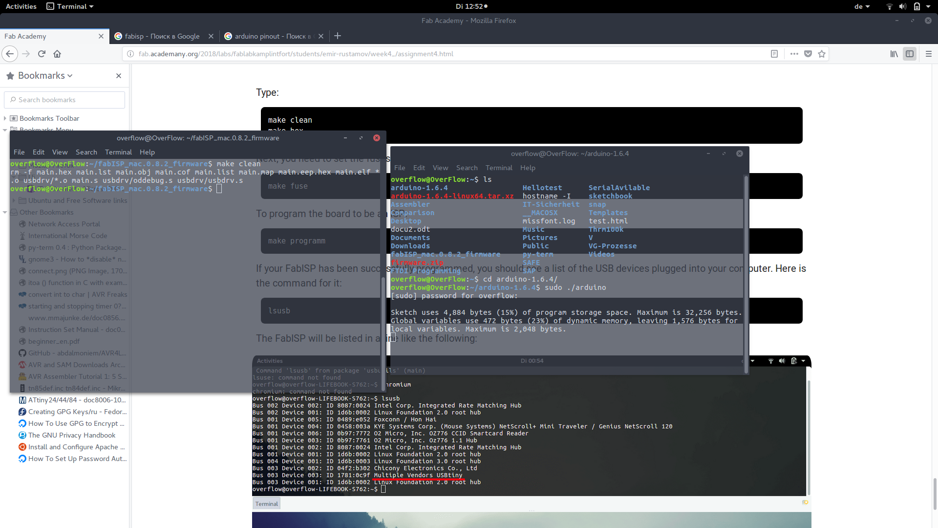
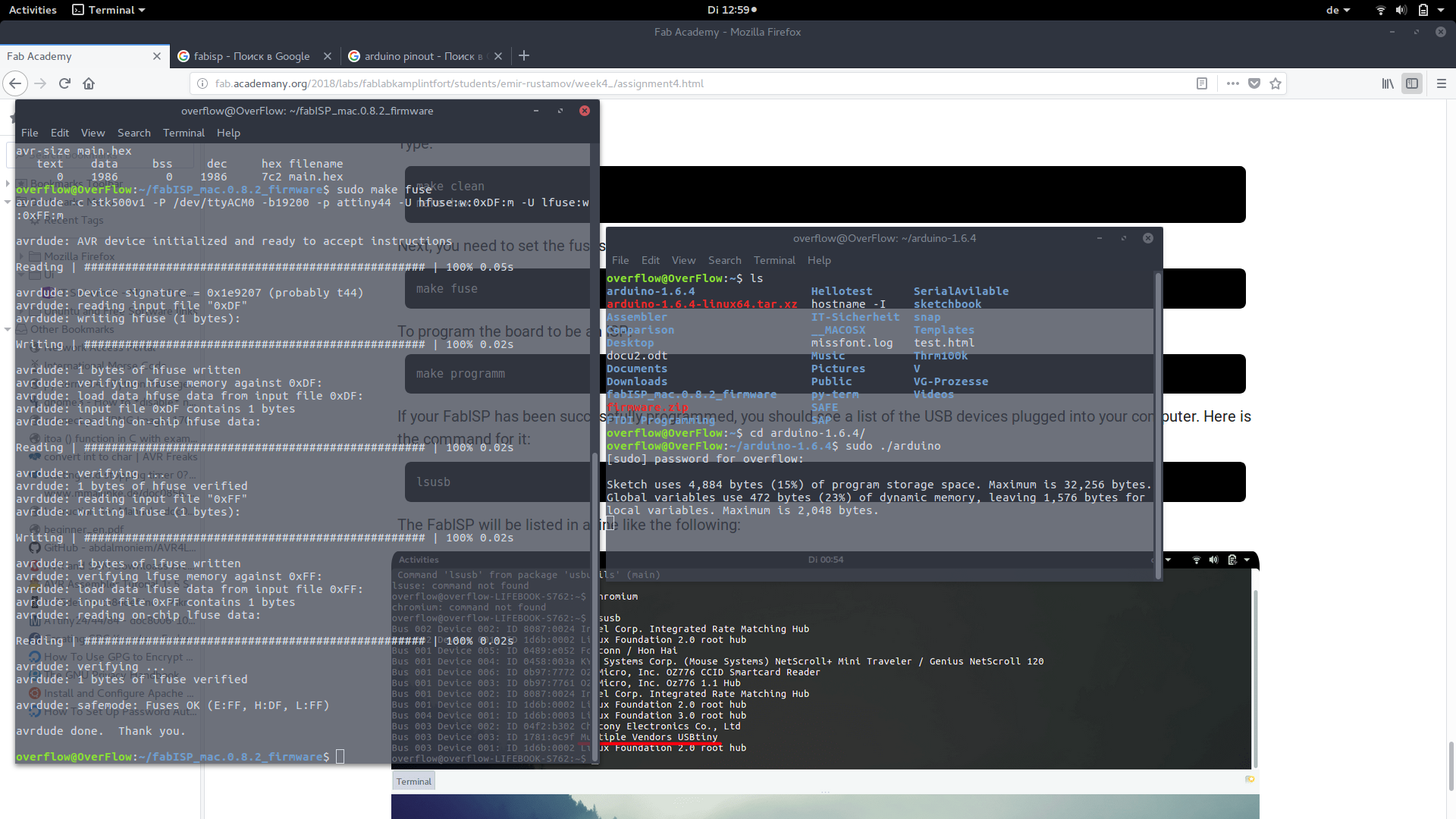 Next, you need to set the fuses so your board will use the external clock (crystal)
make fuse
 To program the board to be an ISP:
make program
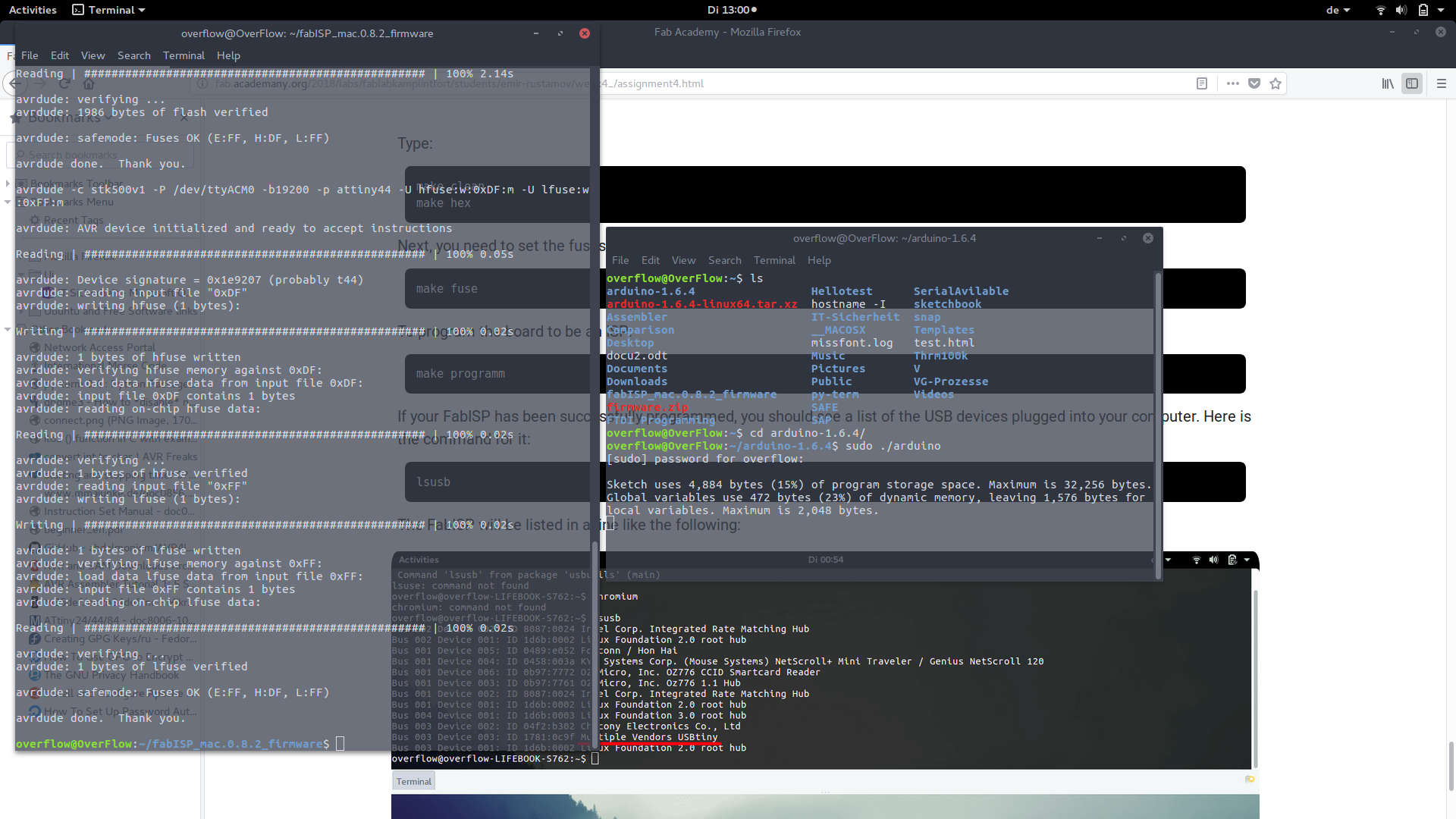
  overflow@OverFlow:~/fabISP_mac.0.8.2_firmware$ sudo make program
  avrdude -c stk500v1 -P /dev/ttyACM0 -b19200 -p attiny44 -U flash:w:main.hex:i

  avrdude: AVR device initialized and ready to accept instructions

  Reading | ################################################## | 100% 0.05s

  avrdude: Device signature = 0x1e9207 (probably t44)
  avrdude: NOTE: "flash" memory has been specified, an erase cycle will be performed
           To disable this feature, specify the -D option.
  avrdude: erasing chip
  avrdude: reading input file "main.hex"
  avrdude: writing flash (1986 bytes):

  Writing | ################################################## | 100% 3.40s

  avrdude: 1986 bytes of flash written
  avrdude: verifying flash memory against main.hex:
  avrdude: load data flash data from input file main.hex:
  avrdude: input file main.hex contains 1986 bytes
  avrdude: reading on-chip flash data:

  Reading | ################################################## | 100% 2.14s

  avrdude: verifying ...
  avrdude: 1986 bytes of flash verified

  avrdude: safemode: Fuses OK (E:FF, H:DF, L:FF)

  avrdude done.  Thank you.

  avrdude -c stk500v1 -P /dev/ttyACM0 -b19200 -p attiny44 -U hfuse:w:0xDF:m -U lfuse:w:0xFF:m

  avrdude: AVR device initialized and ready to accept instructions

  Reading | ################################################## | 100% 0.05s

  avrdude: Device signature = 0x1e9207 (probably t44)
  avrdude: reading input file "0xDF"
  avrdude: writing hfuse (1 bytes):

  Writing | ################################################## | 100% 0.02s

  avrdude: 1 bytes of hfuse written
  avrdude: verifying hfuse memory against 0xDF:
  avrdude: load data hfuse data from input file 0xDF:
  avrdude: input file 0xDF contains 1 bytes
  avrdude: reading on-chip hfuse data:

  Reading | ################################################## | 100% 0.02s

  avrdude: verifying ...
  avrdude: 1 bytes of hfuse verified
  avrdude: reading input file "0xFF"
  avrdude: writing lfuse (1 bytes):

  Writing | ################################################## | 100% 0.02s

  avrdude: 1 bytes of lfuse written
  avrdude: verifying lfuse memory against 0xFF:
  avrdude: load data lfuse data from input file 0xFF:
  avrdude: input file 0xFF contains 1 bytes
  avrdude: reading on-chip lfuse data:

  Reading | ################################################## | 100% 0.02s

  avrdude: verifying ...
  avrdude: 1 bytes of lfuse verified

  avrdude: safemode: Fuses OK (E:FF, H:DF, L:FF)

  avrdude done.  Thank you.
If your FabISP has been successfully programmed, you should see a list of the USB devices plugged into your computer. Here is the command for it:
lsusb
The FabISP will be listed in a line like the following:
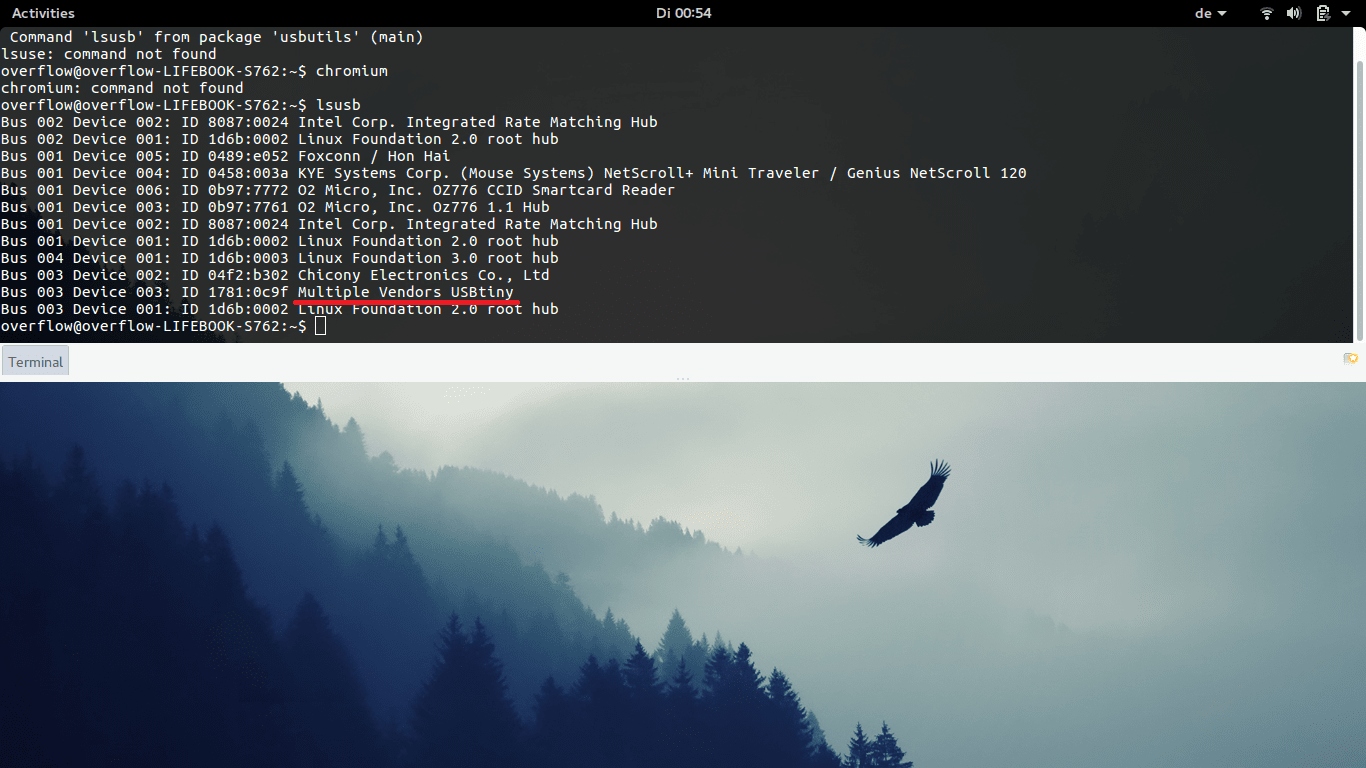 And don't forget to unsolder the Jumper xD


