1. Introduction (Cristian)
1.1 Concept
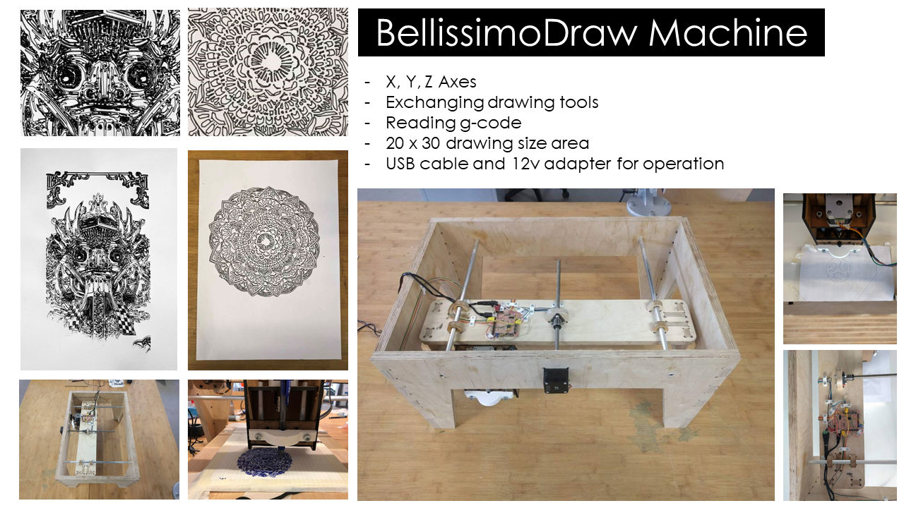
The scope of this assignment was to build a machine that is functional and produces movements. Having the desire to experiment with different axes, that implies having motors that move the construction in different directions, the choice of building a universal plotting device came. This concept is not new and has been previously done during the Fab Academy years. Main inspiration for the project came from a former MIT graduate building an axis tool, A Machine that Makes. The aim was to supple the lab with a machine that draws and works and can be used by other students.
1.2 Functionality
The functionality is straight forward. There are three axis X, Y, Z that by means of traveling and holding the tool, creates the drawing. Similar to laser cutter (only with one more axis) and to a 3D printer, the machine follows a path, using the g-code provided. Since g-code is read directly by the Universal Plotter and sent to the satshakit-grblthe intention was to use that at first in order to produce the drawings.
1.2.1 Multi-plotter, aiming to replace the tooling.
The intention is not create a perfect plotter, otherwise we just recreate an ink printer that is out there and is commonly used. The aim is to create a tool that draws digitally, with all it's imperfect lines, creating a 2D digital art using electronics only.
1.3 Approach and sketches.
In order to better understand the common vision of the machine, as well as divide the tasks, we used sketches on paper and whiteboard. During this process we understood the benefits and drawbacks of our decisions as well as made constraints regarding the size and the area of drawing we want to produce.
Whiteboard Sketch
.jpg)
Paper Sketch
.jpg)
.jpg)
.jpg)
1.3.1 Separate tasks by dividing the 3 axes X,Y,Z.
As a result we were able to divide the tasks and act accordingly by designing our own parts.
1.3.2 Cooperation and communication. Team Work.
Crytical part during the design and construction process was a clear communication and setting aside all the expectations. Having a clear discussion in terms of sizes and adjustments as well as final functionality.
2 X Axis / Bed (Emir)
2.1 Concept / Sketch
At the beginning we have divided our tasks, so that I had to to the Frame and the x Axies. Well we like the Frame of the BigRep, especially the edges, thats why I have designed something similar. We have decided to make the Frame out of 18mm PlyWood and und cut it with the big CNC machine out. We have choosen 18 mm of MDF in order to make our machine stiff and stable.2.2 Motors / Mechanics used
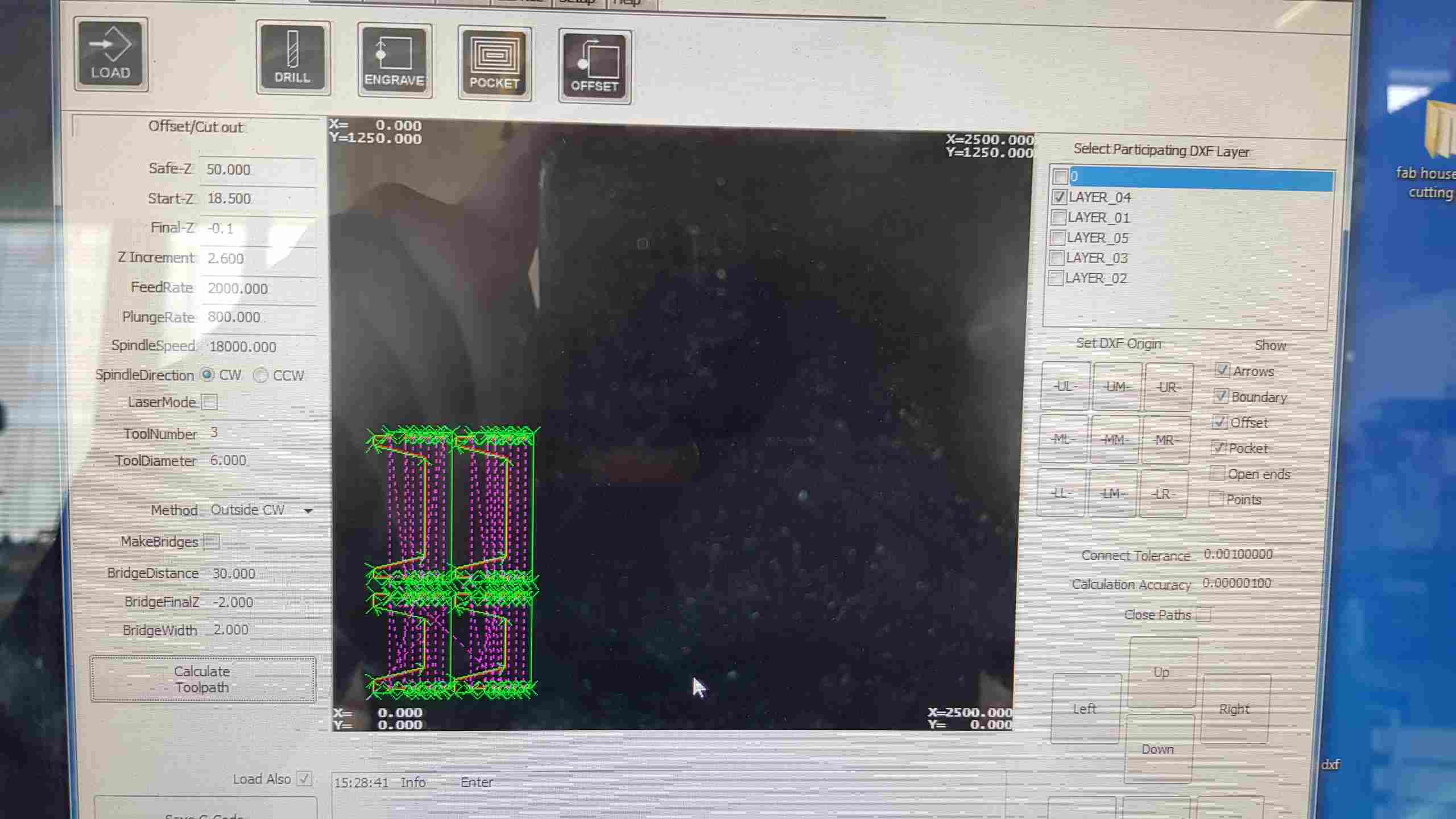
For the x Axies I have used Nema17 with 300 mm spiral. Here is the datasheet of it.2.3 Schetches Fusion 360
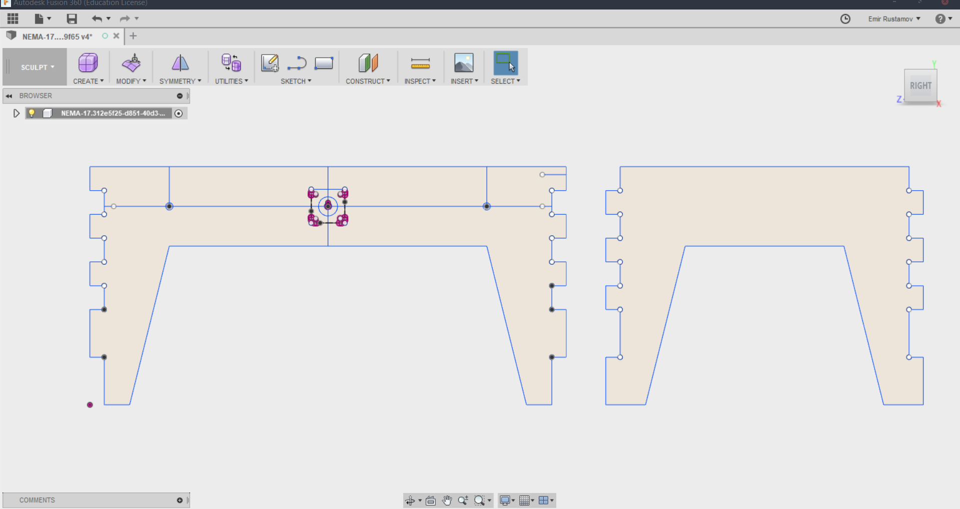
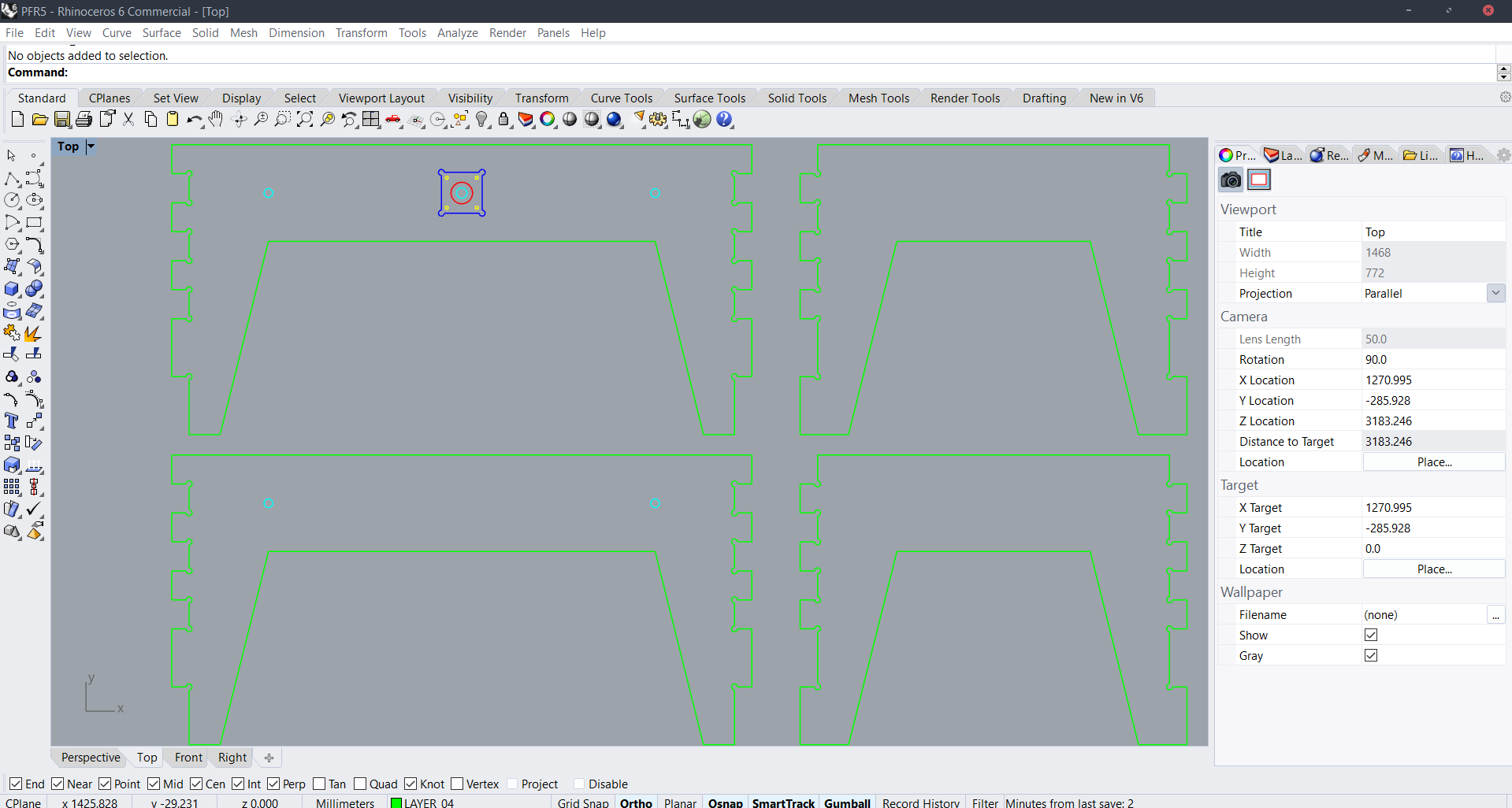
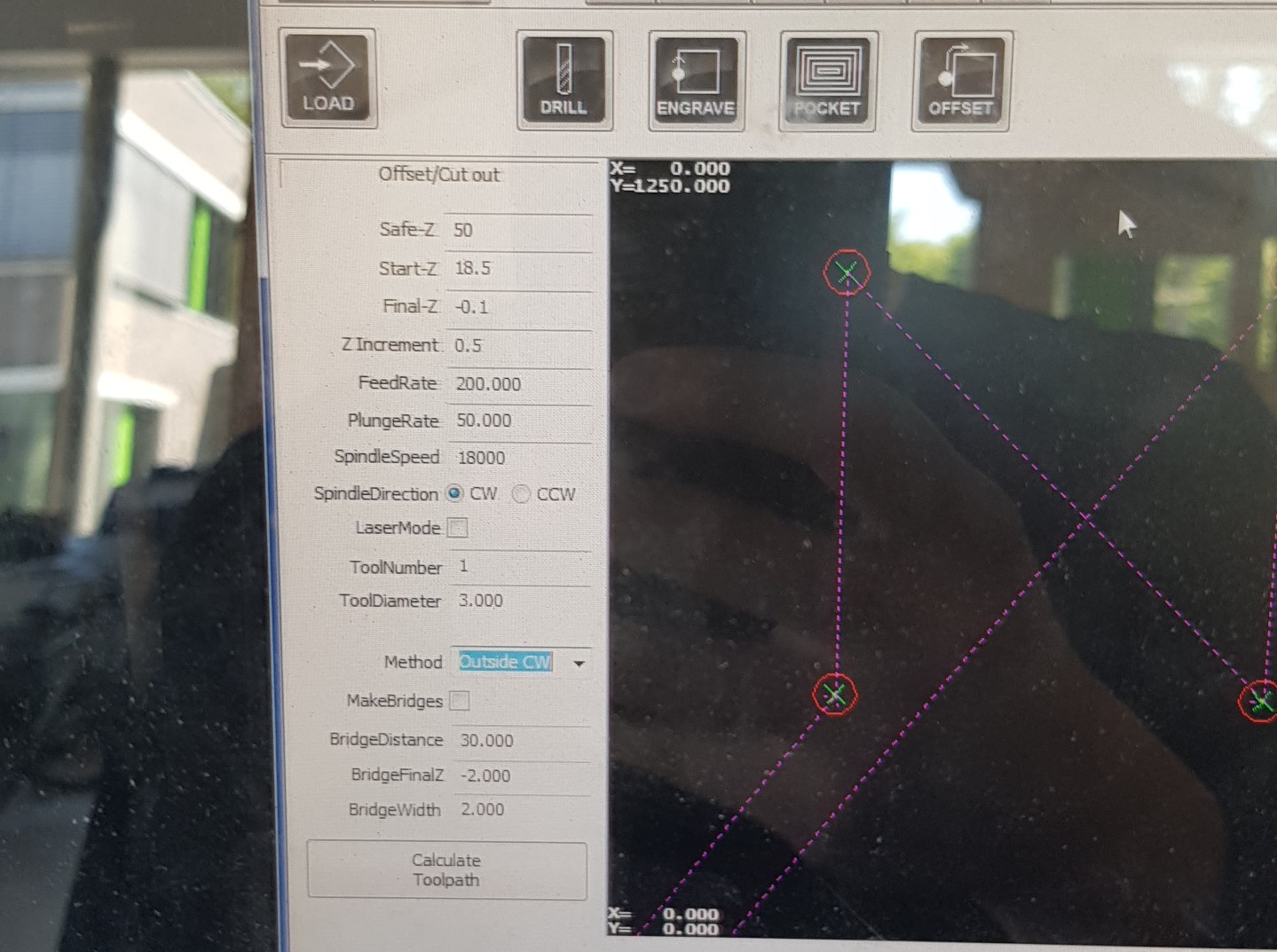
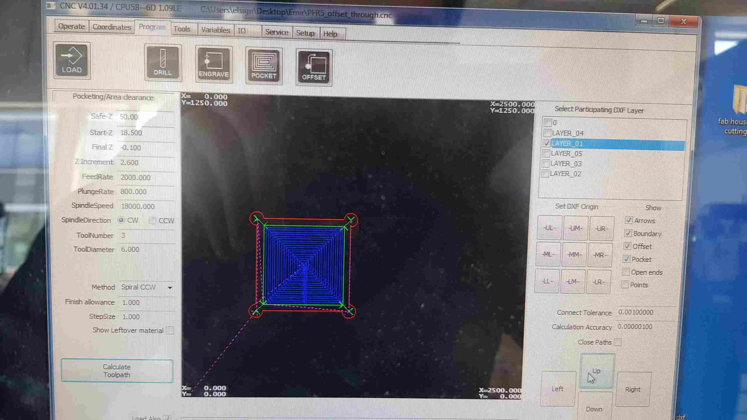
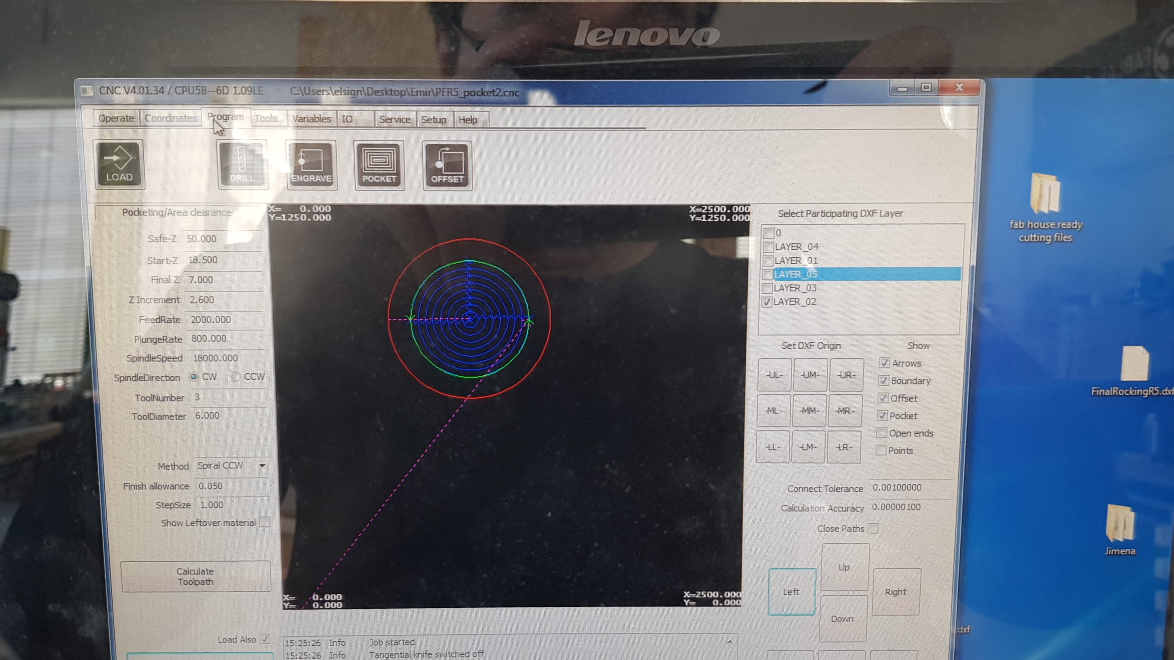
-Blue Layers: is for the Pocket
-Red Layer: is for some offset, that motor has
-Asure Layer: is for the Nema17 spiral
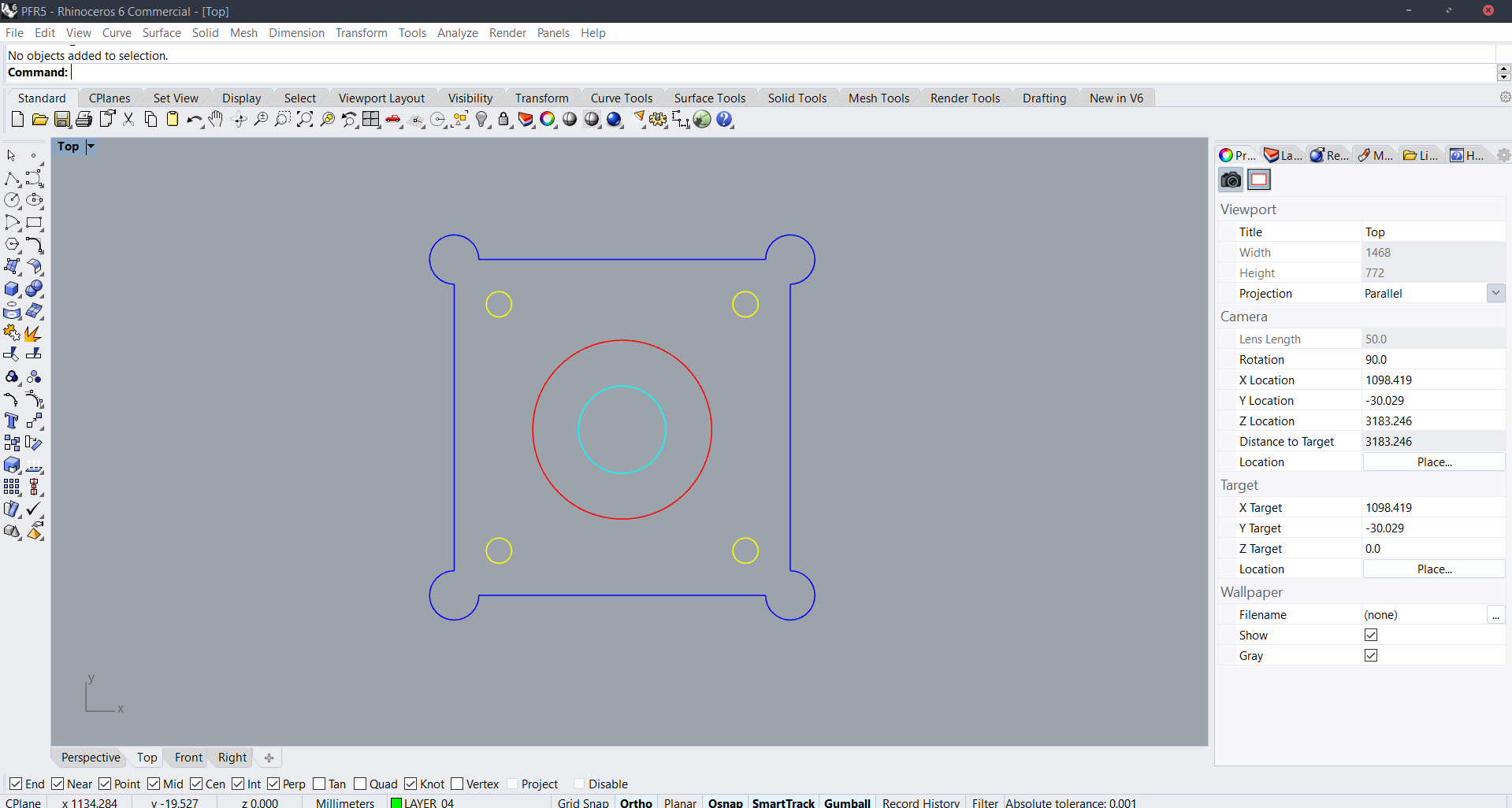
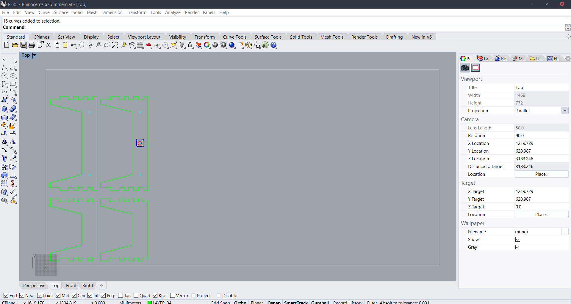
Reminder: Make the holes at least 3.2mm in DM
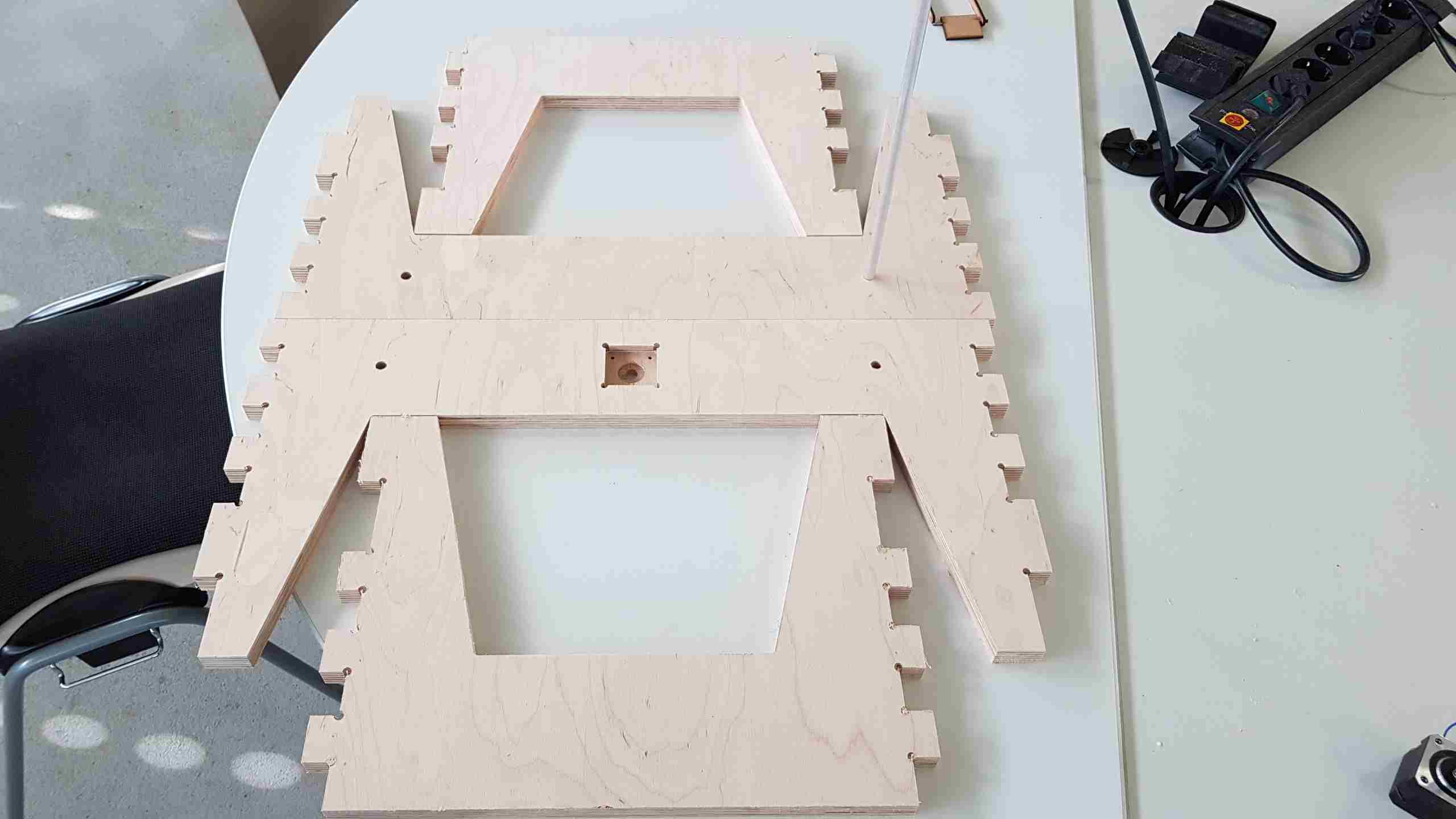
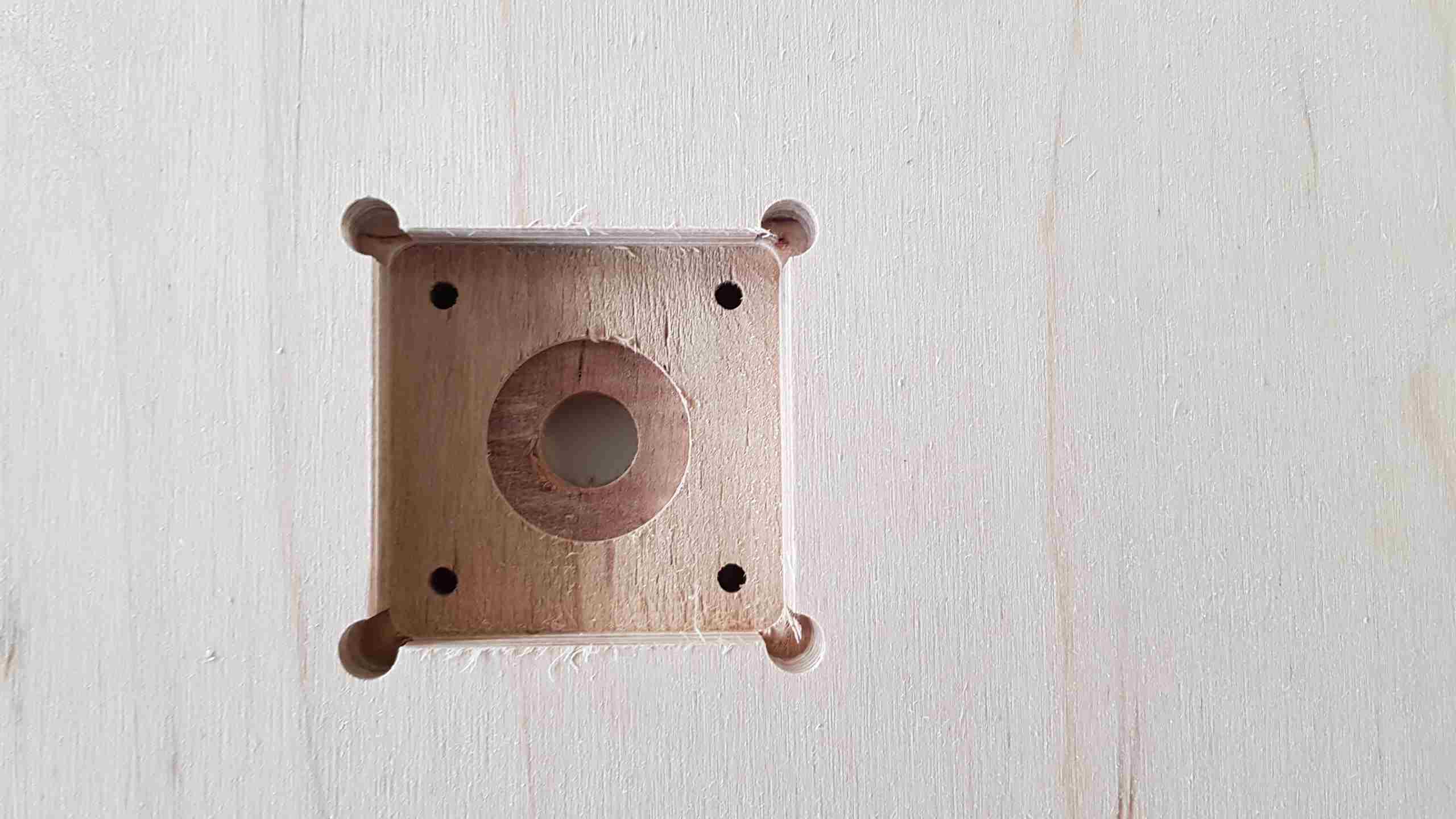
2.4 End result
3. Y Axis / Bed (Cristian)
3.1 Concept / Sketch
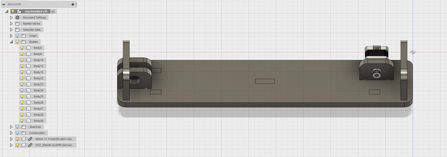
In order to have a fast traveling axis, I decided to construct my bed are with the stepper motor attached to the traveling belt. It was also interesting to have a traveling belt incorporated with rod guide stepper motors and see what would result in terms of speed and accuracy.
3.2 Motors / Mechanics used
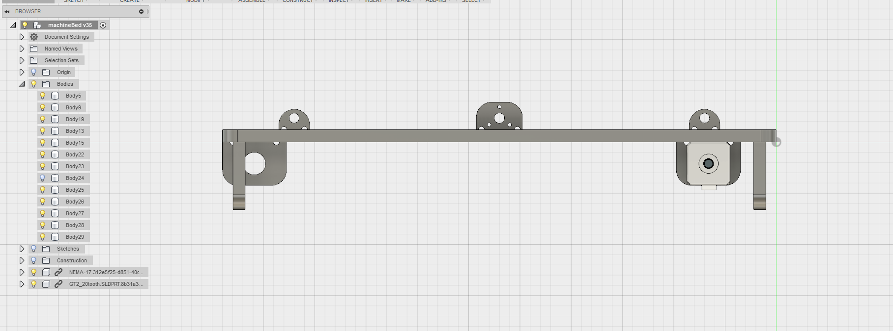
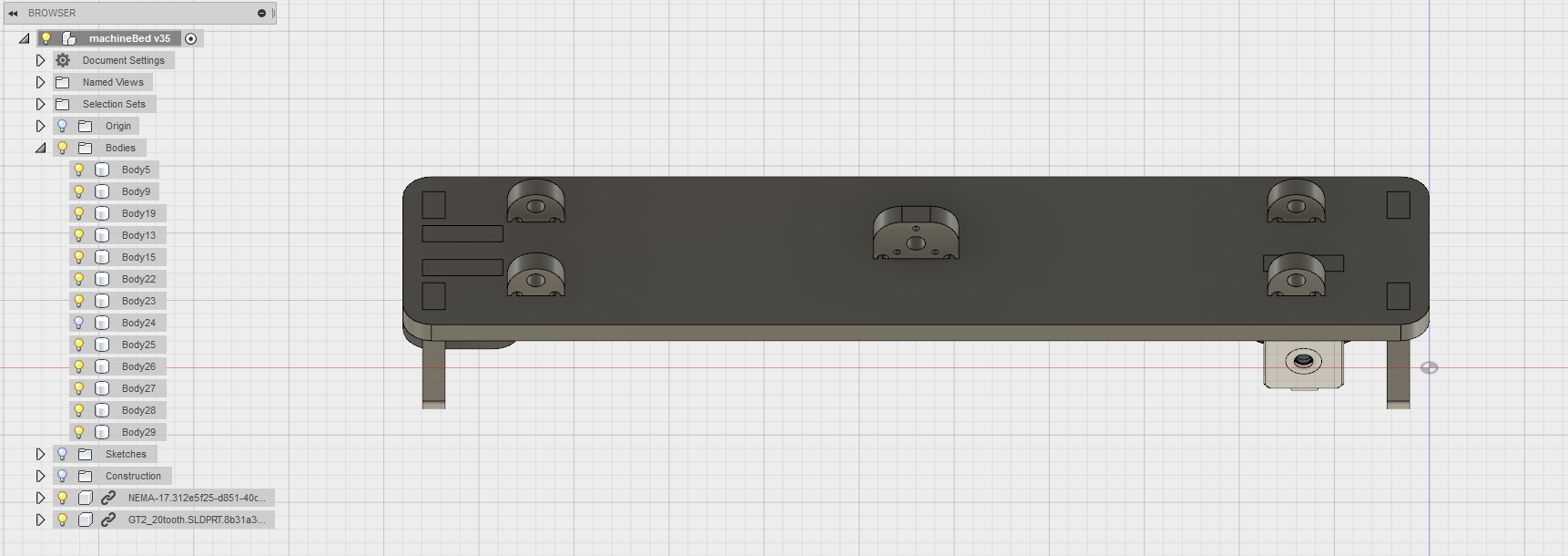
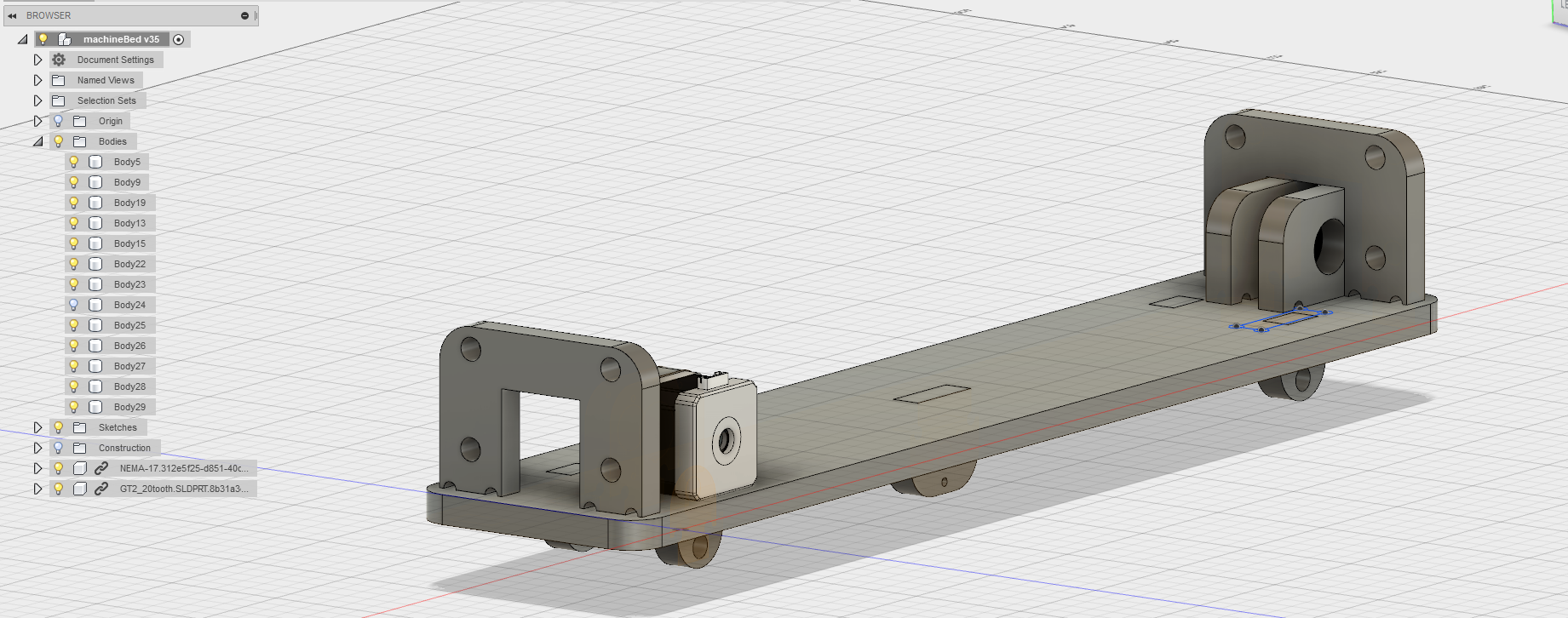
3.3 Sketches Fusion 360
RIght view.
Angle view.
Flipped view.
Guiding view.
End result.
3.4 Assembly
.jpg)
Resulted pieces from the CNC.
.jpg)
3.5 End result
Assembled pieces of the bed.
.jpg)
.jpg)
.jpg)
Mounting the barring.
.jpg)
Mounting the travel guide for the motor.
.jpg)
On the main frame.
.jpg)
4 Z Axis / Bed (Cello)
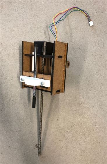
4.1 Concept / Sketch
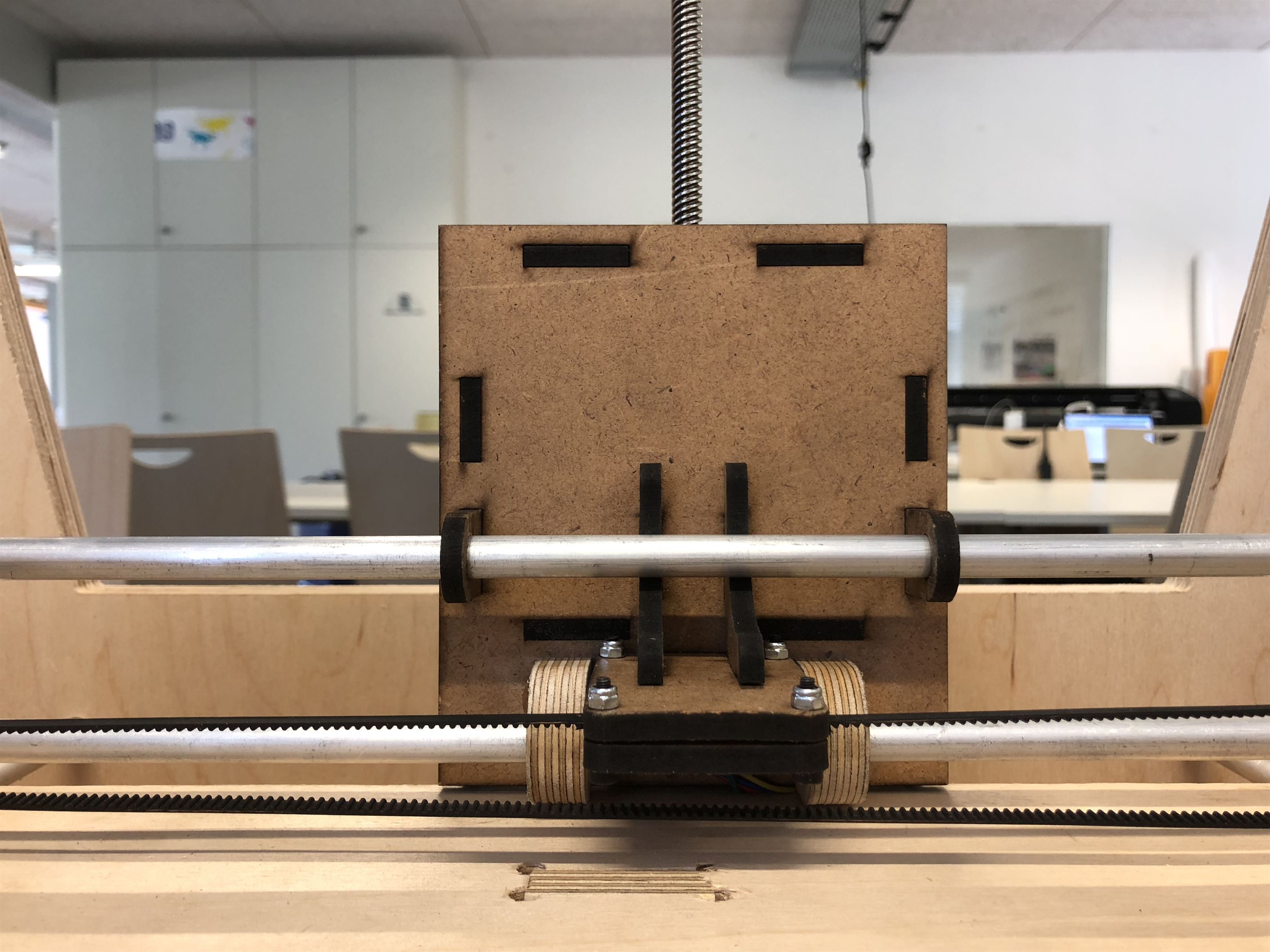
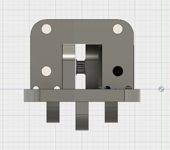
To let the z platform move in y direction, the belt is squized between two plates.
The two rods are guided the z movement so it can moves stabily.
4.2 Motors / Mechanics used
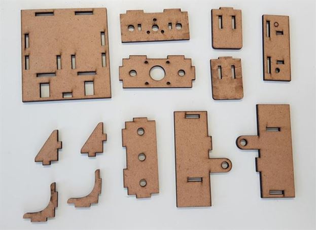
4.3 Schetches Solidworks
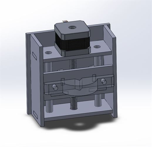
I used Solidworks to 3d CAD the model.
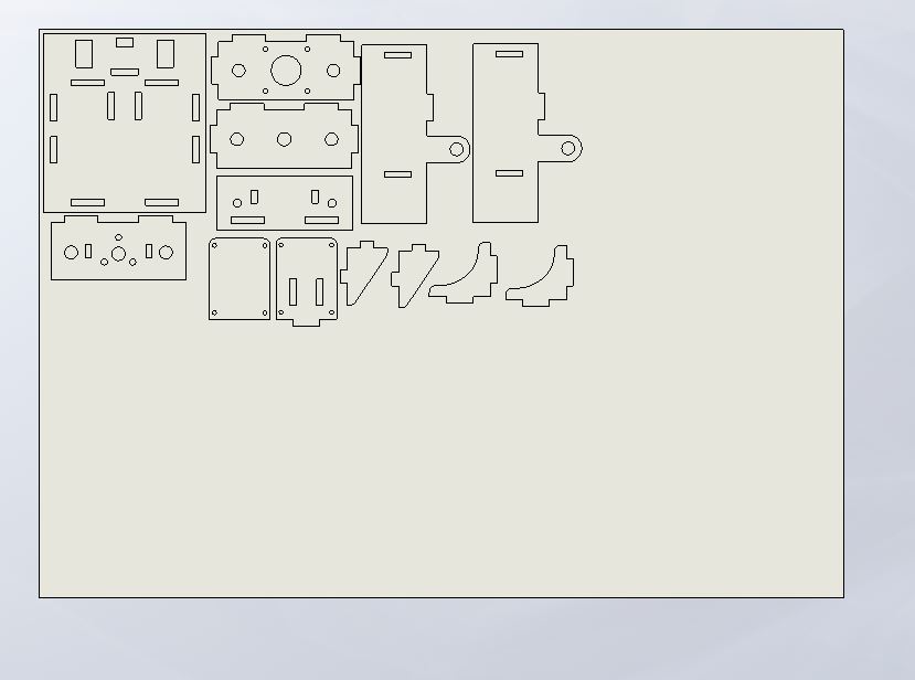
I made the 2d drawing in solidworks and then save it as an dxf file to laser cut it.
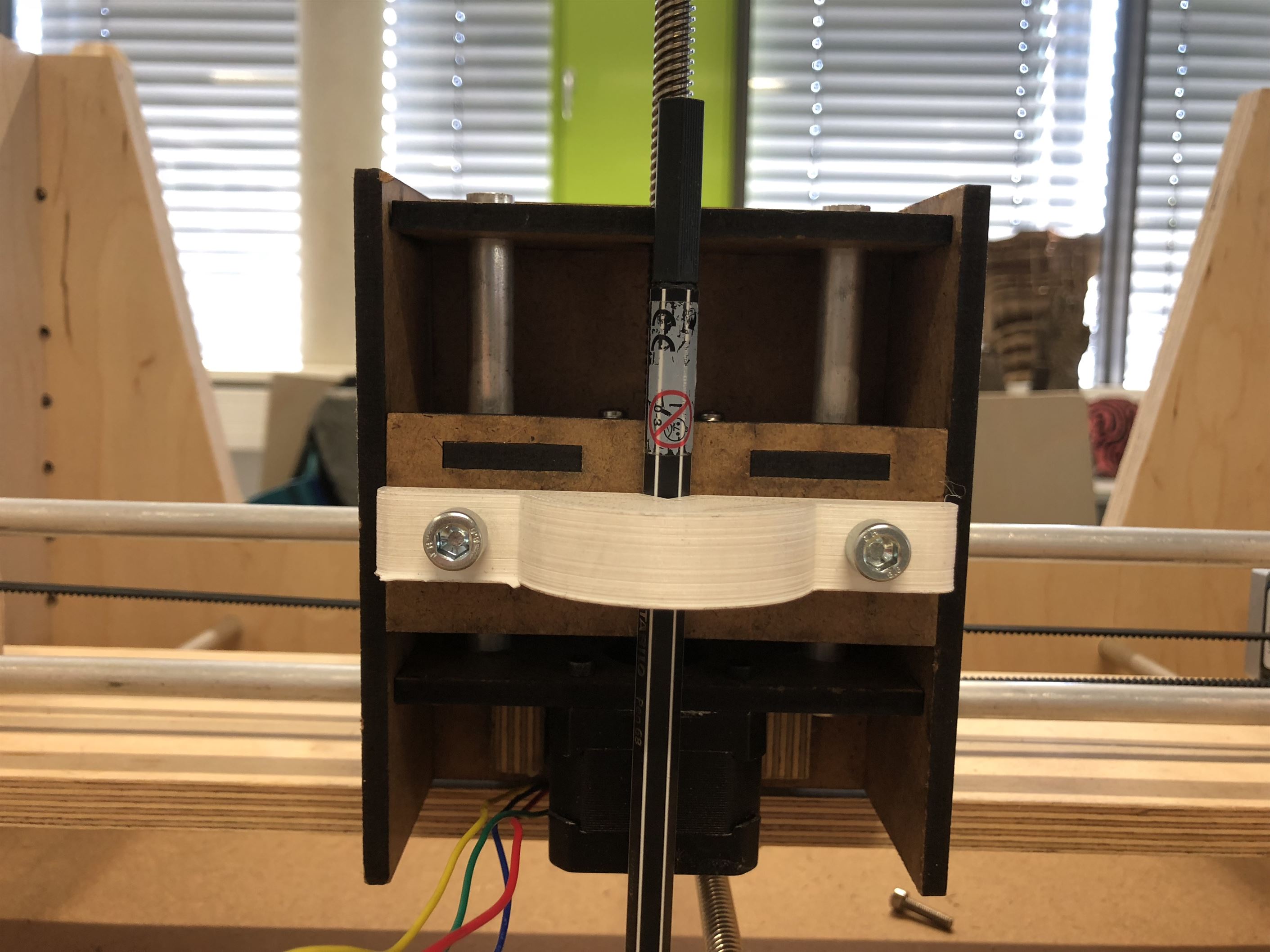
4.4 End result
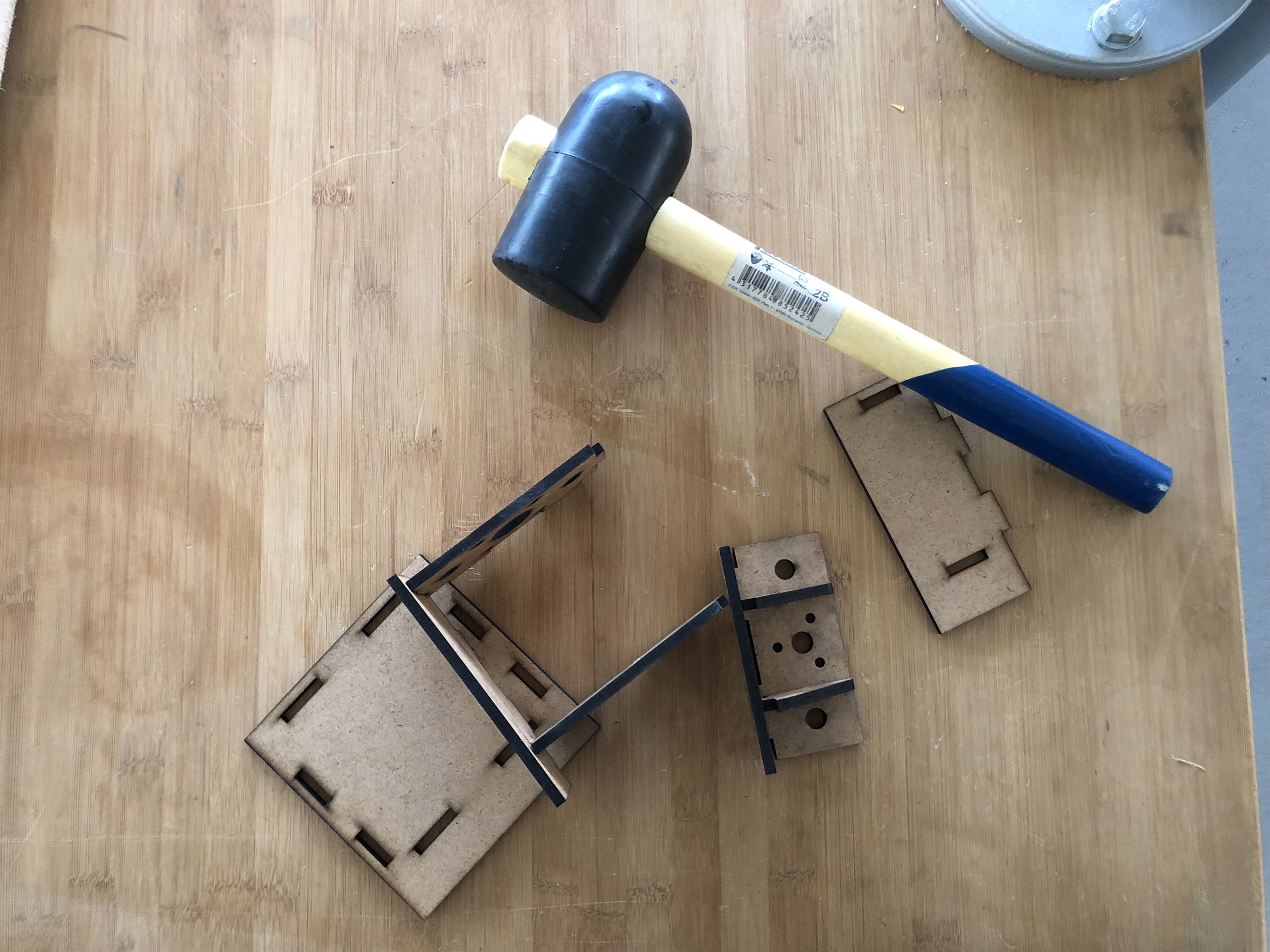
After I that I had to hammer them to press firt all the parts together.
Finally, I can attach them together to the whole machine.
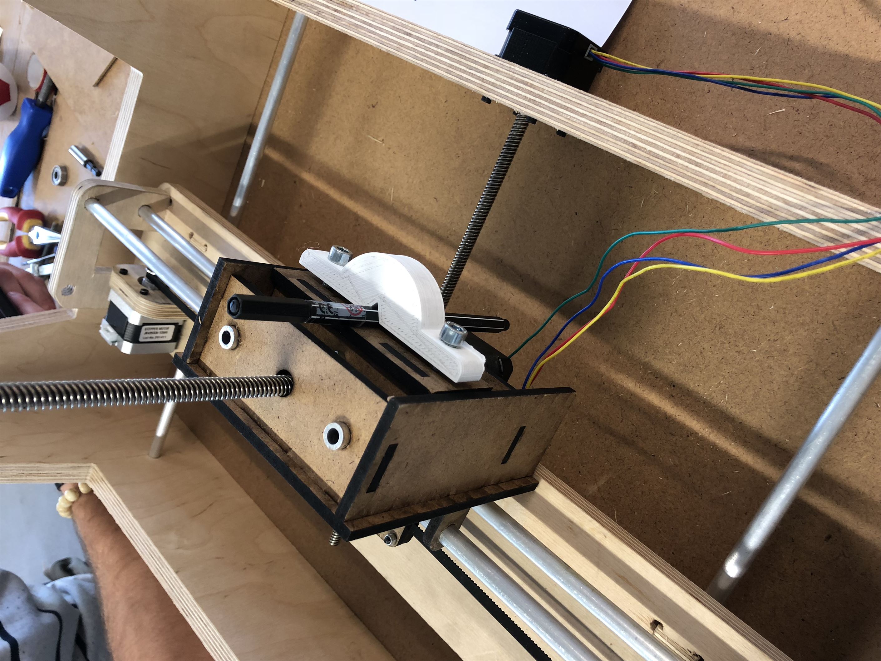
5 Final Assembly
5.1 Putting the machine together
Side view.
.jpg)
Top view.
.jpg)
5.2 Moving machine by hand
Moving by hand
5.3 Cabling
(Cristian)5.4 PCB driver board for the motors
(Cello)MP6500 Stepper Motor Driver Carriers PCB board
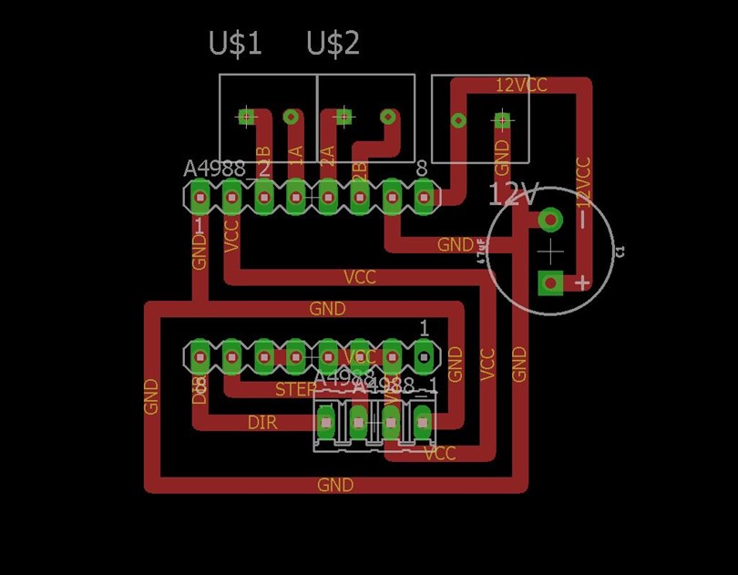
The board is design to simplify the connection of the stepper motor driver ti the Satsha GBRL board.
 Pololu
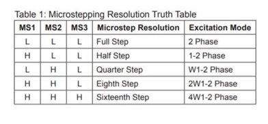
Pins MS1, MS2 and MS3 have to be connected in 5V in the MP6500 stepper motor driver carriers so that it offers 1/16 step microstepping.
This driver operates from 4.5V ti 35V and can diliver ip to approximately 1.5 A.
Current limiter on board
There is an on board timer poteniometer for setting the curent limit, turn it counter clockwise to decrease the current.
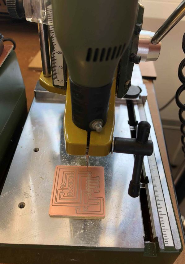
After finished milling the PCB, we need to drill the holes with the diameter of 0.9 mm and 1 mm.
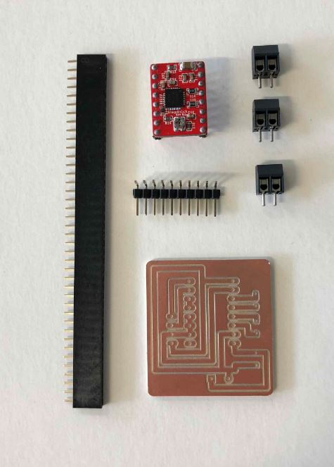
Part list:
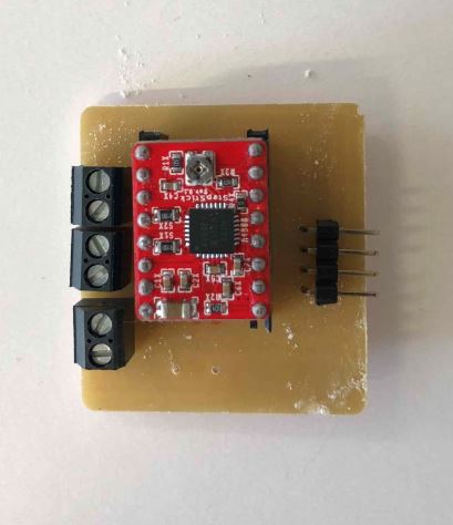
Solder them all in the board and plug the pololu stepper motor driver.
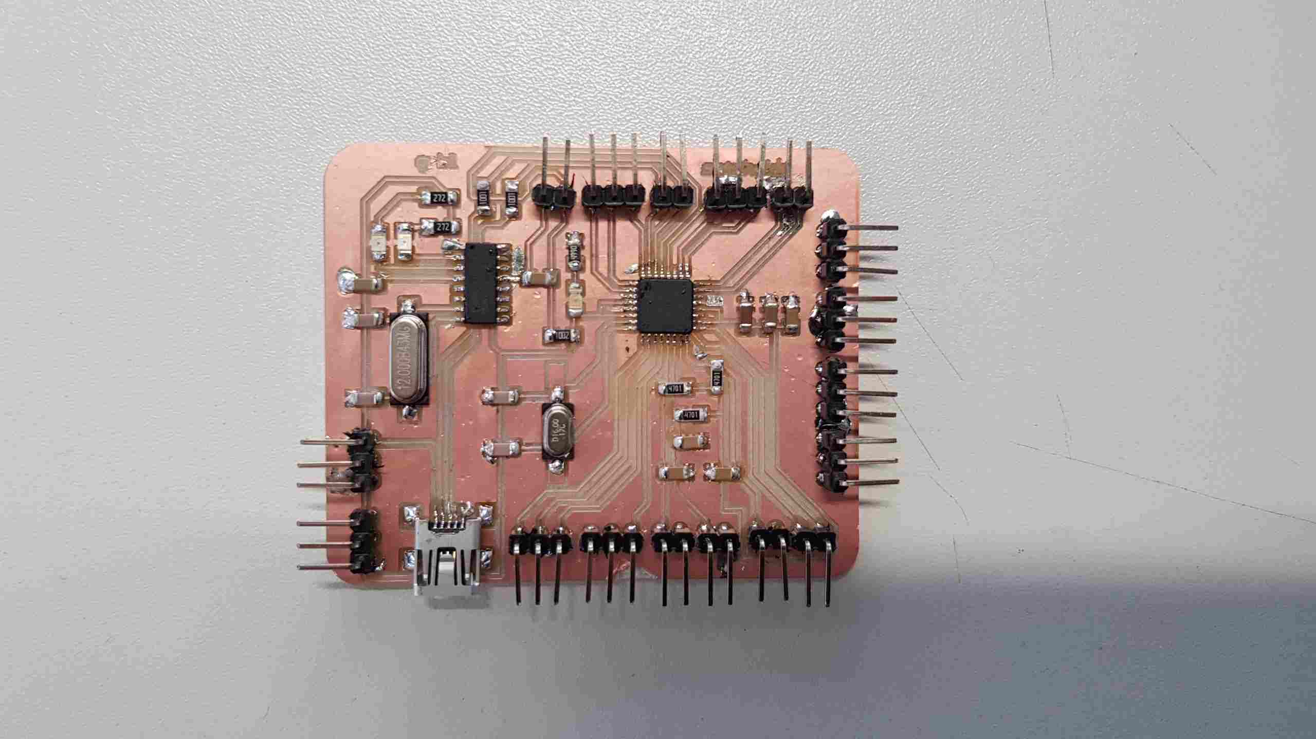
5.5 PCB satshakit-GRBL
(Emir)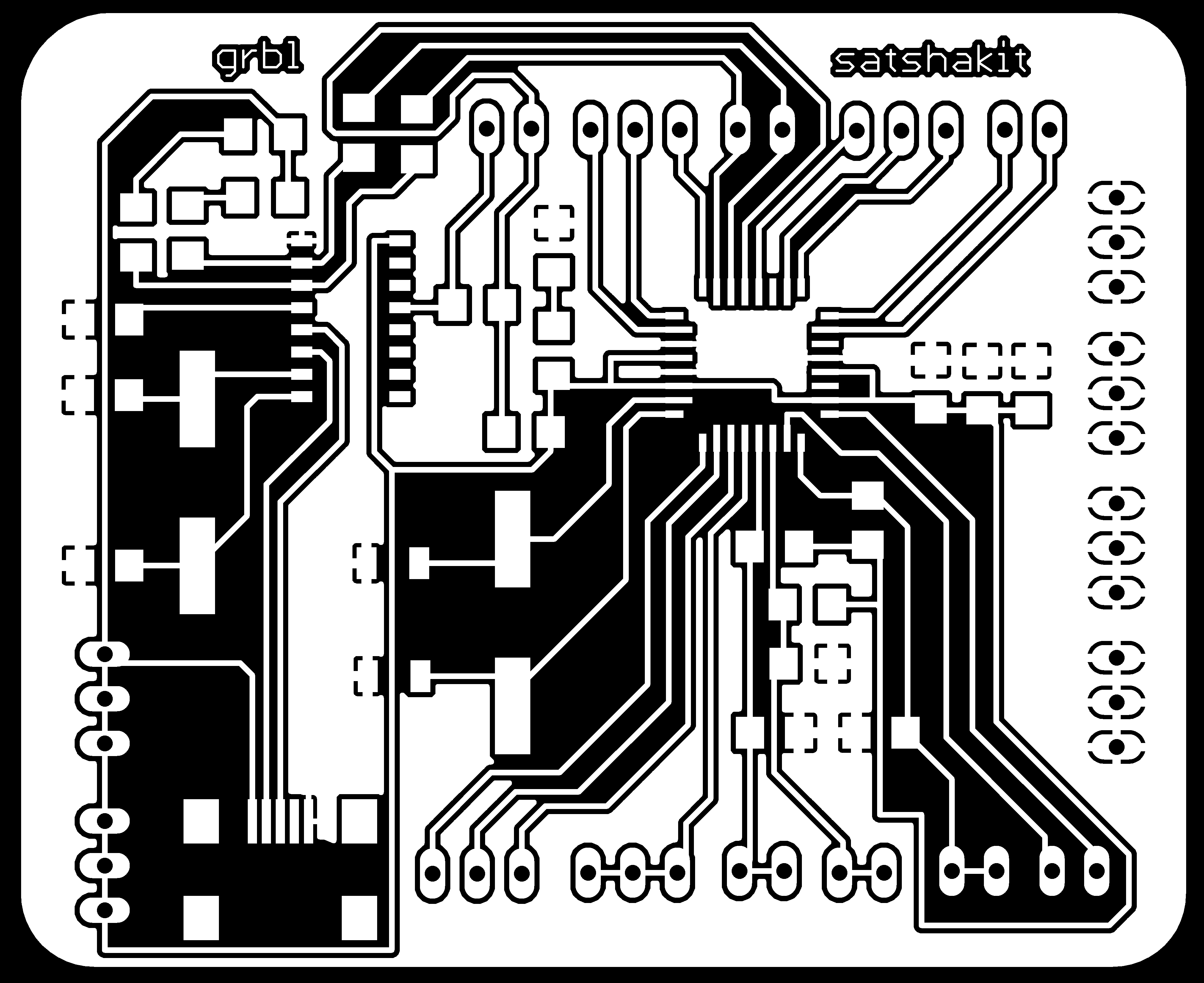

5.6 Mounting PCBS
(Cristian)Cable Mangement
The 3d CAD of cable holder.
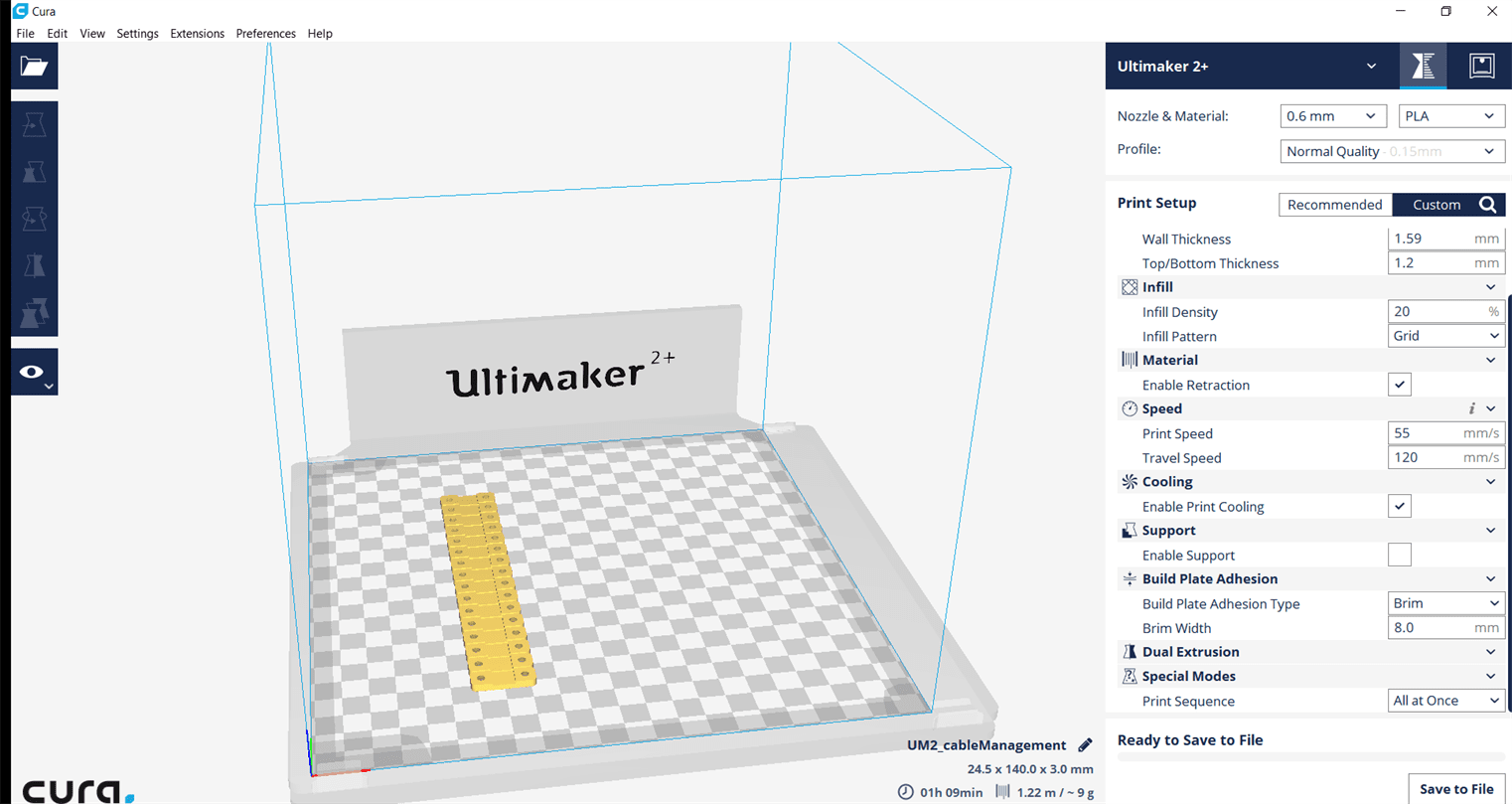
Slicer for 3D pint the cable holders.
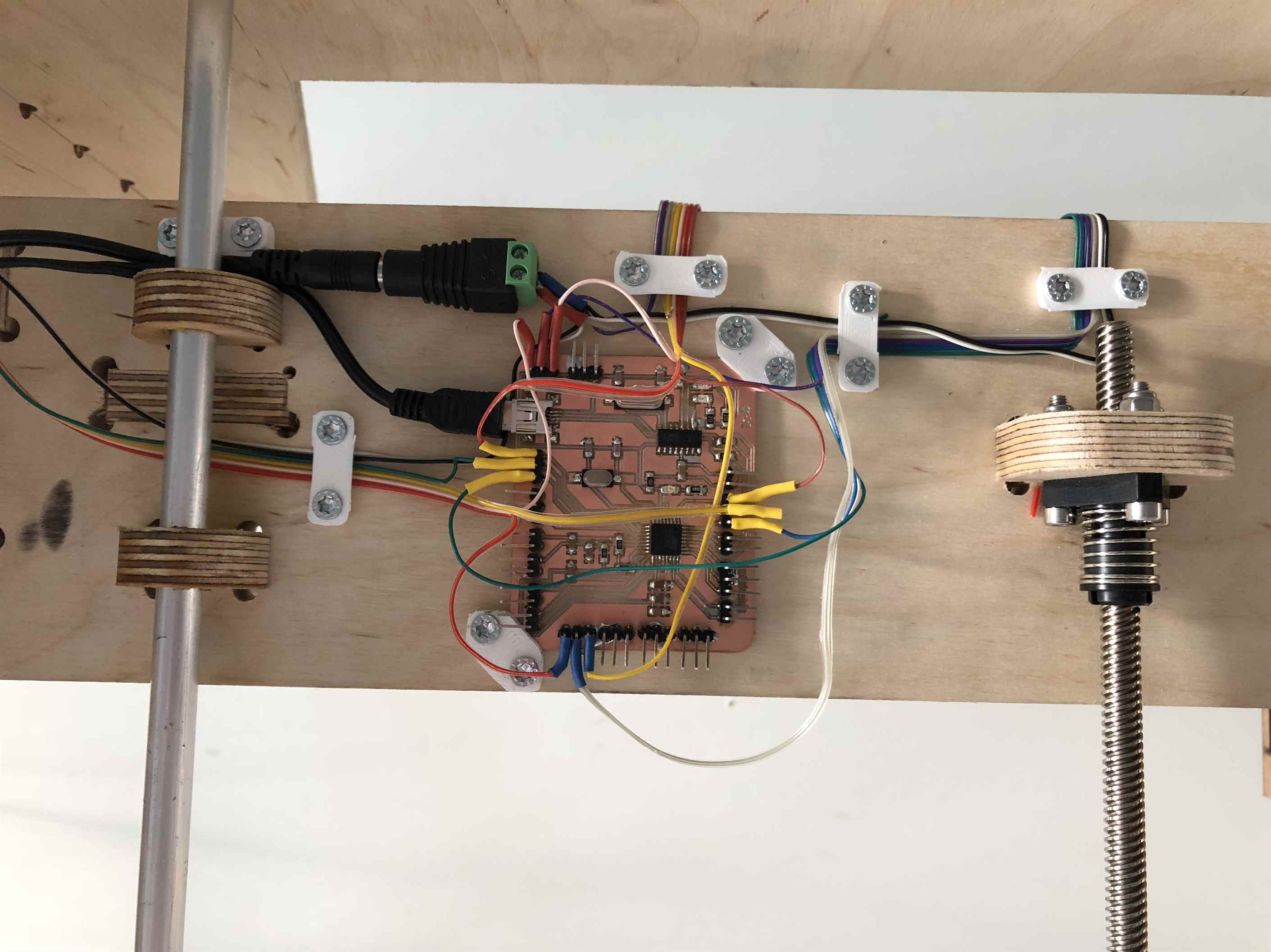
Manage all the cables with the 3d printed cable holders.
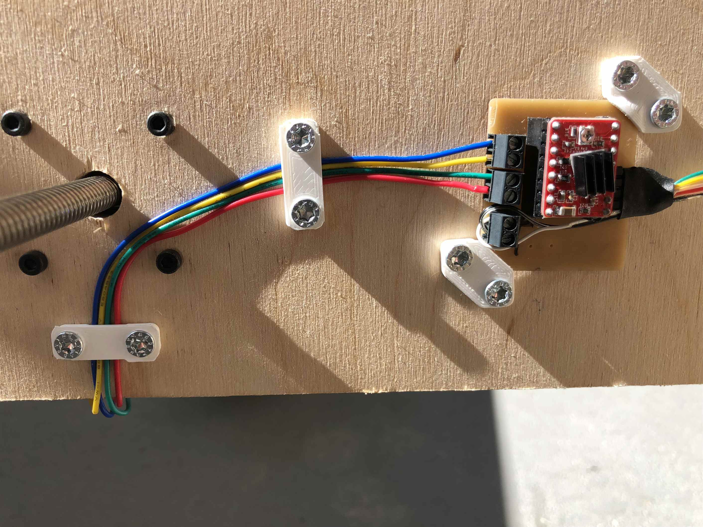
Cable management.
Software
Microcontroller
GBRL is a controller for CNC Milling which run on Atmega 328.
Download GRBLprogram and upload it on the satshakit-grbl board using the arduino IDE.
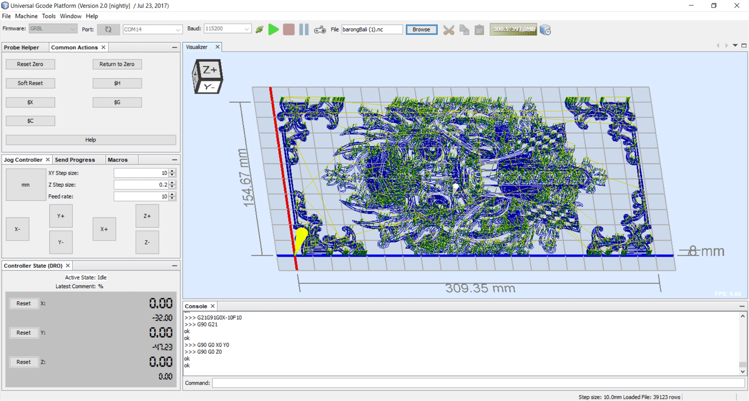
Desktop Software
Download and install UGS Platform.
On the software use $$ command to get the current setting.
Grbl v1.1 Commands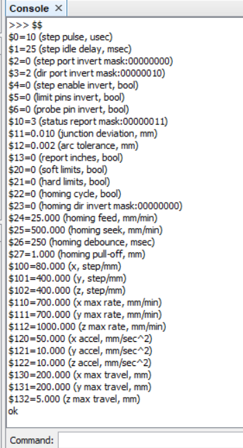
To change the setting just simply type the the parameter on the console for example "100 = 200" which set that x-axis travel resolution is 200 step/mm.
GCode
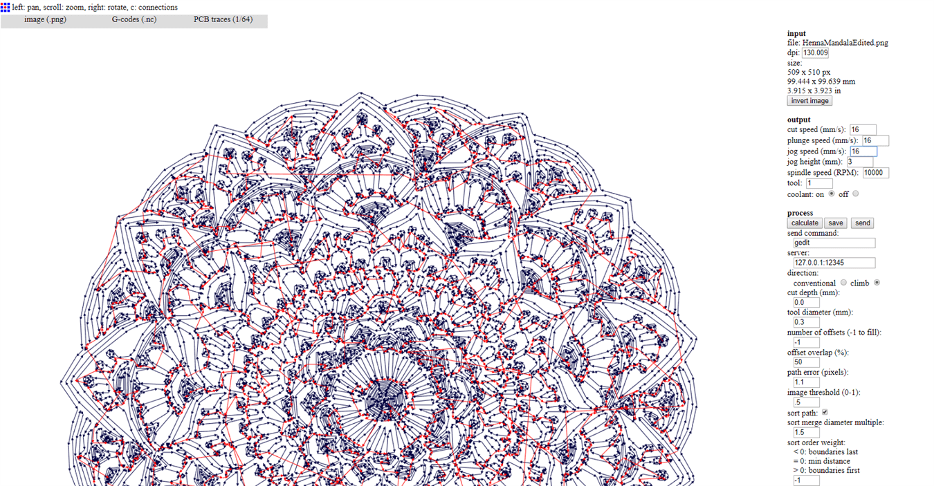
The Fab modules is used to generate the g-code.
Those are the parameters that I have used to draw with my machine.
5.6 Test the machine
5.7 Final drawings

This is the first try to draw on a notebook.
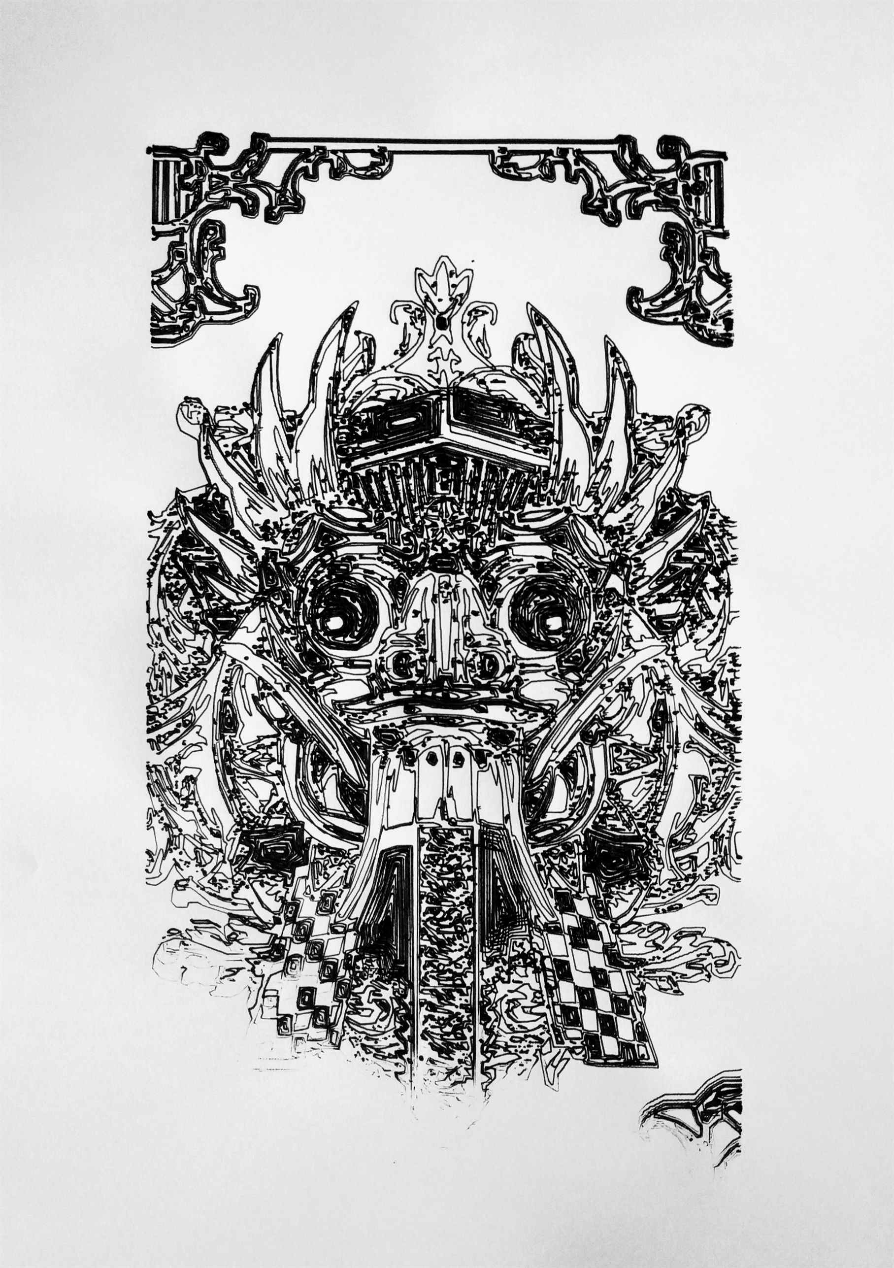
A2 drawing of a Barong.
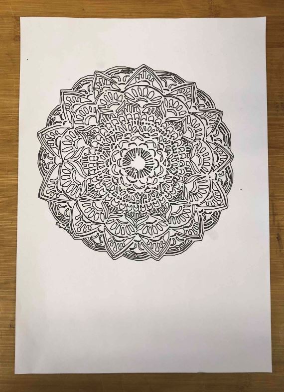
Madala drawing from our machine.