Mechanical design
Download files
For laser cut / 3D print data, check Enclosure page from the global menu.
Rack and pinion
Protolight suppose to have automatically focal length adjustment feature using data from ToF range sensor. I chose rack and pinion, and rotation servo motor to impliment it.
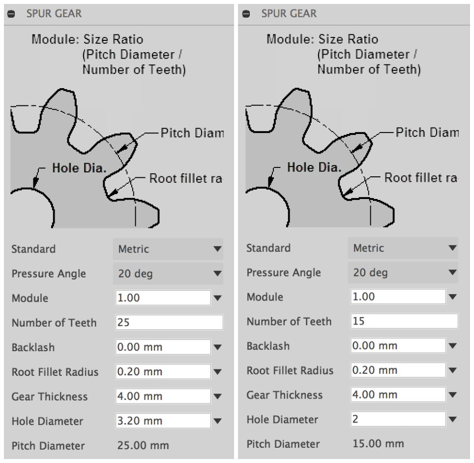
Designing the pinion
The point is to keep the “Module” size same, and decide the “Pitch Diameter” by adjusting the “Number of Teeth”. As I first fixed the size (diameter) and the position of the gears then tried to make teeth on it in my process, I was keep struggling with the “Spur Gear script” in Fusion because it does not allow us to set the diameter in beforehand. The key is, although it might sounds obvious, “Module” x “Number of Teeth” = “Pitch Diameter”. Keep this in mind when using Spur Gear script on Fusion.
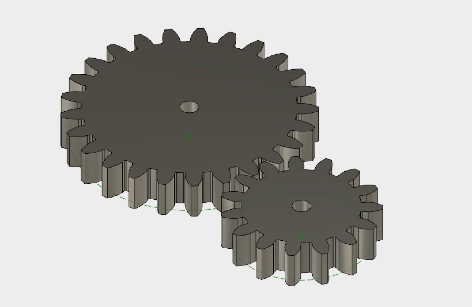
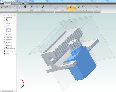
Gear which is attached directly to the motor (right)
Pinion convey the movement of the first gear to the rack and push whole LED and motor module back and forward (left).
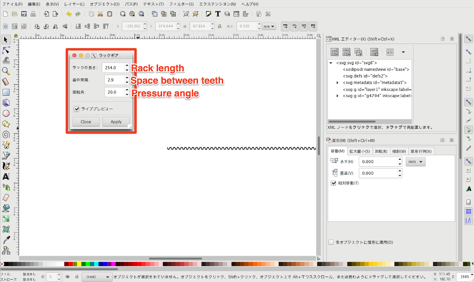
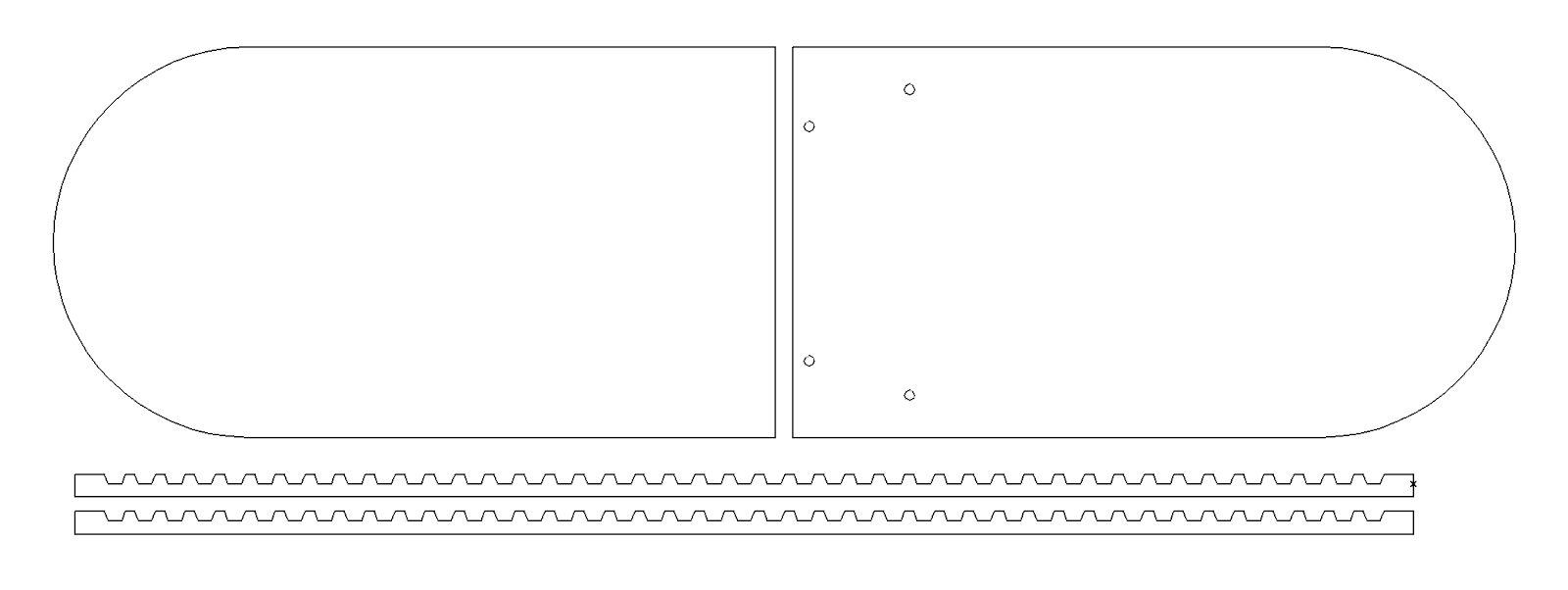
Designing the rack with Inkscape rack gear extension.
https://github.com/braingram/inkscape_rack_gear
Rack length and pressure angle are set same as spur gear generator in Fusion.
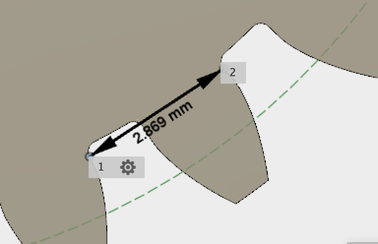
For “Space between teeth”, I measured it in Fusion.
Then I combined those two using Adobe Illustrator to make final laser cut data.
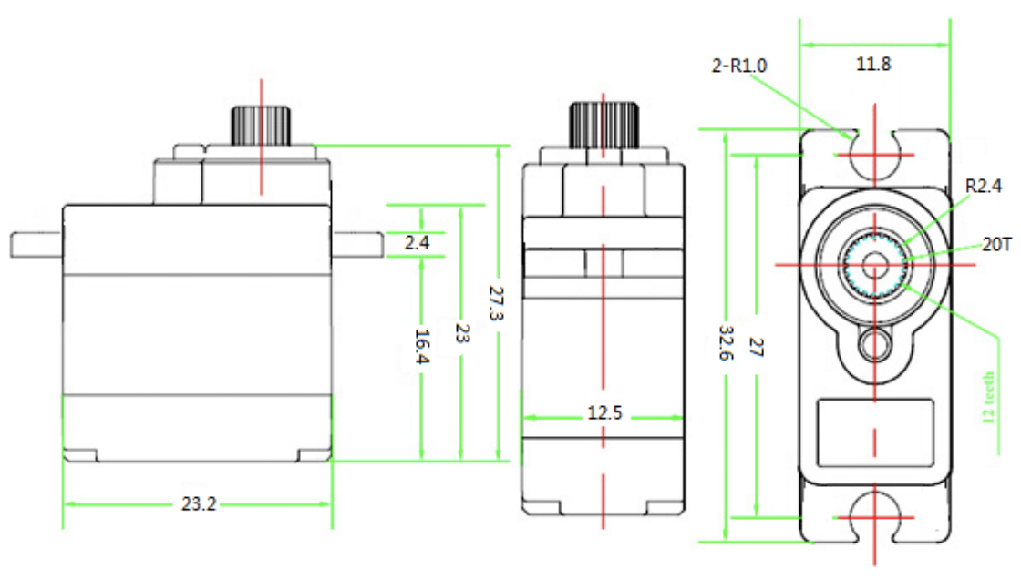
Motor
FS90R (Rotation servo motor)
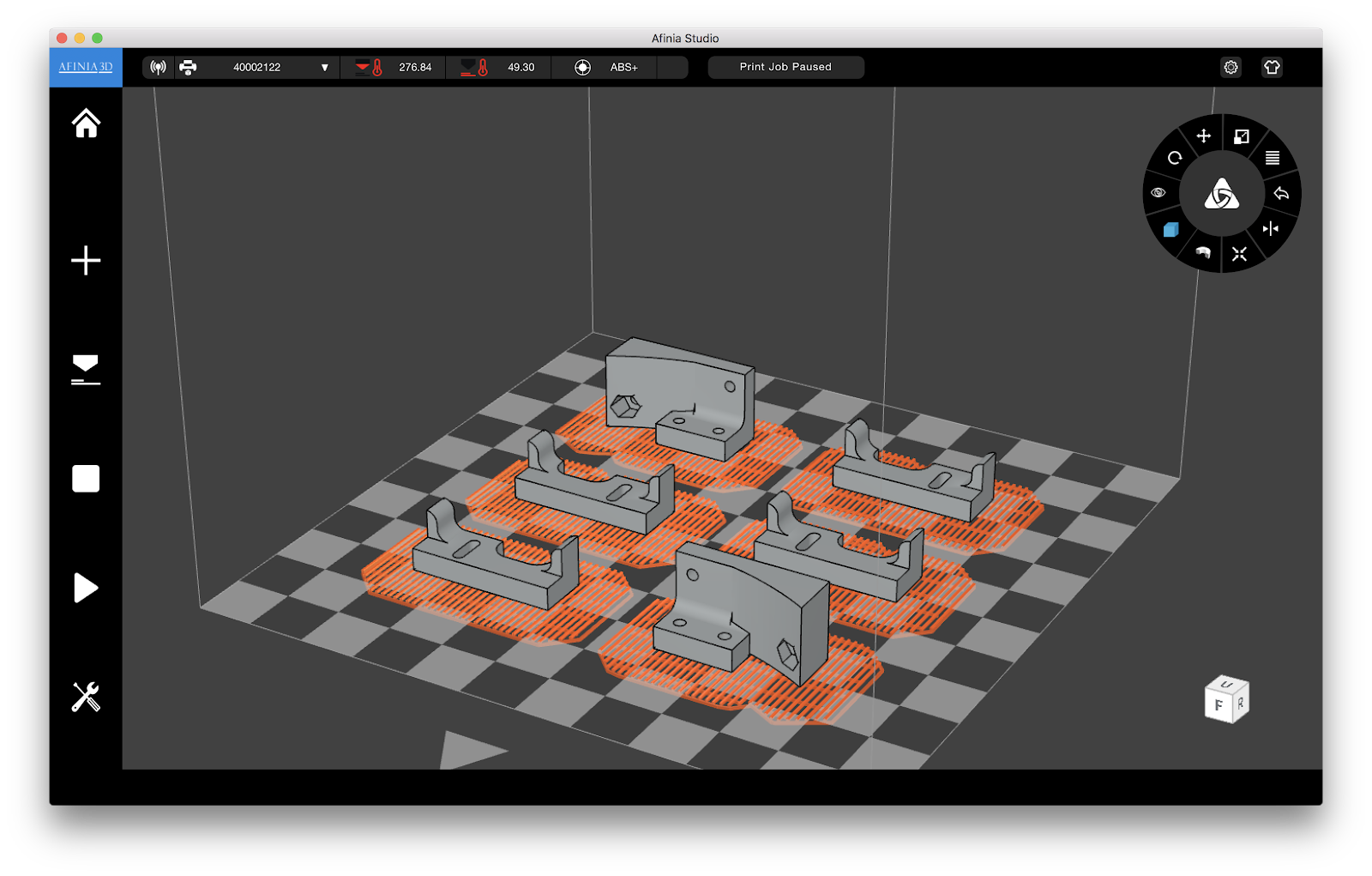
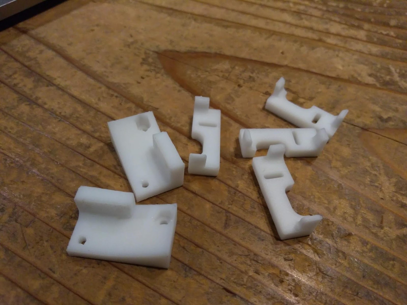
3D Printing parts for fixing the frames
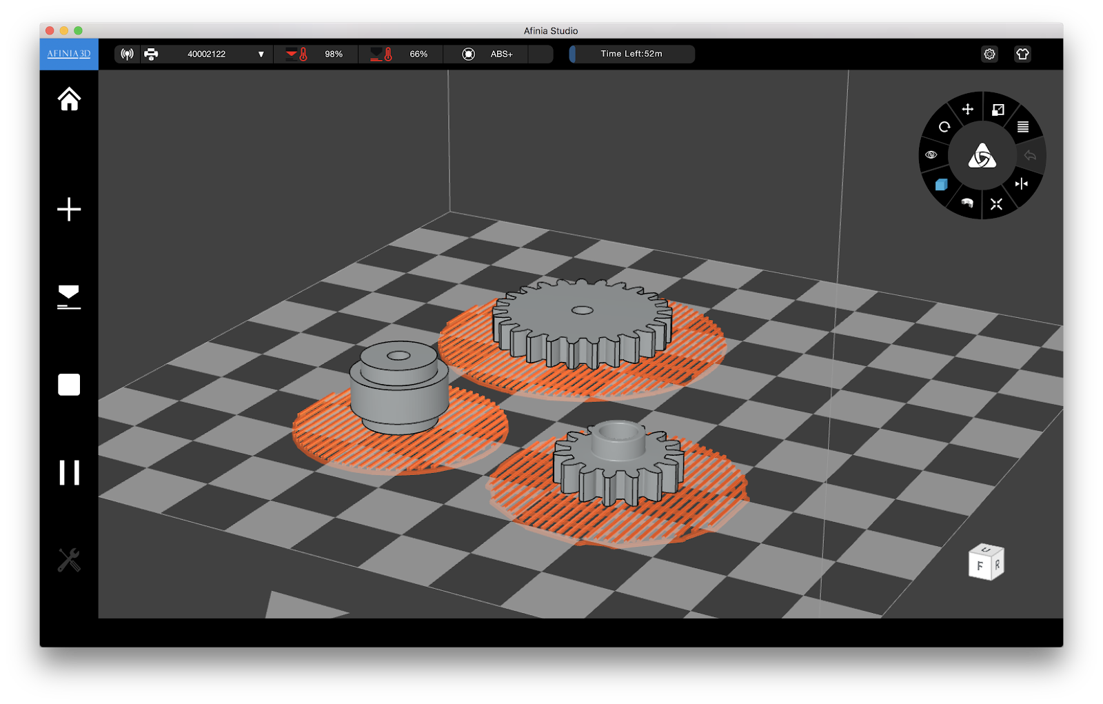
Printing gears
Optical property
Lens
Considering of expanding this light fitting (and switch system) to every corner of the house, I wanted to cut the price as much as possible.
Therefore the lens I am using is from local 100 yen shop (you can get almost any everyday things with $1, extremely common in Japan). I bought a magnifying glass and took the lens.
Since, of cause, no information available on this lens, I conducted simple experiment to measure its focal length and how much distance I need to leave between the lens and the LED board.
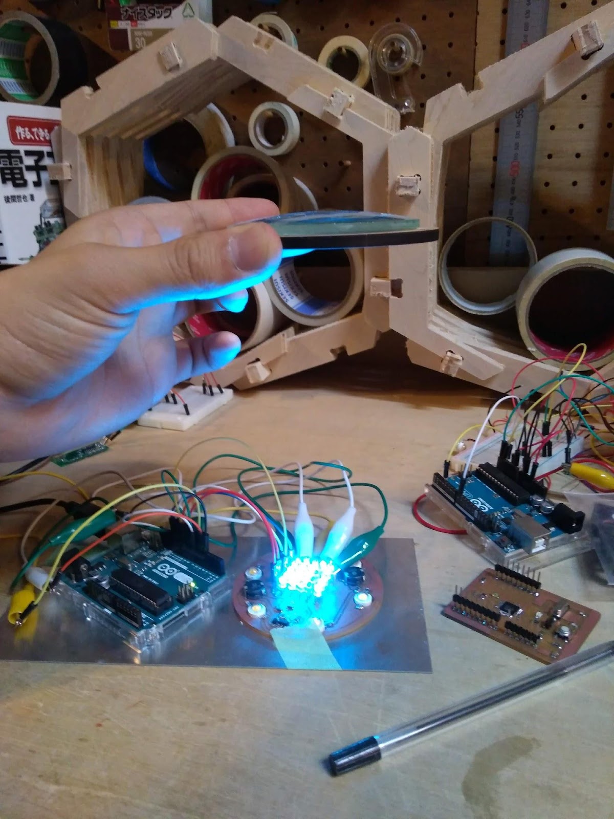
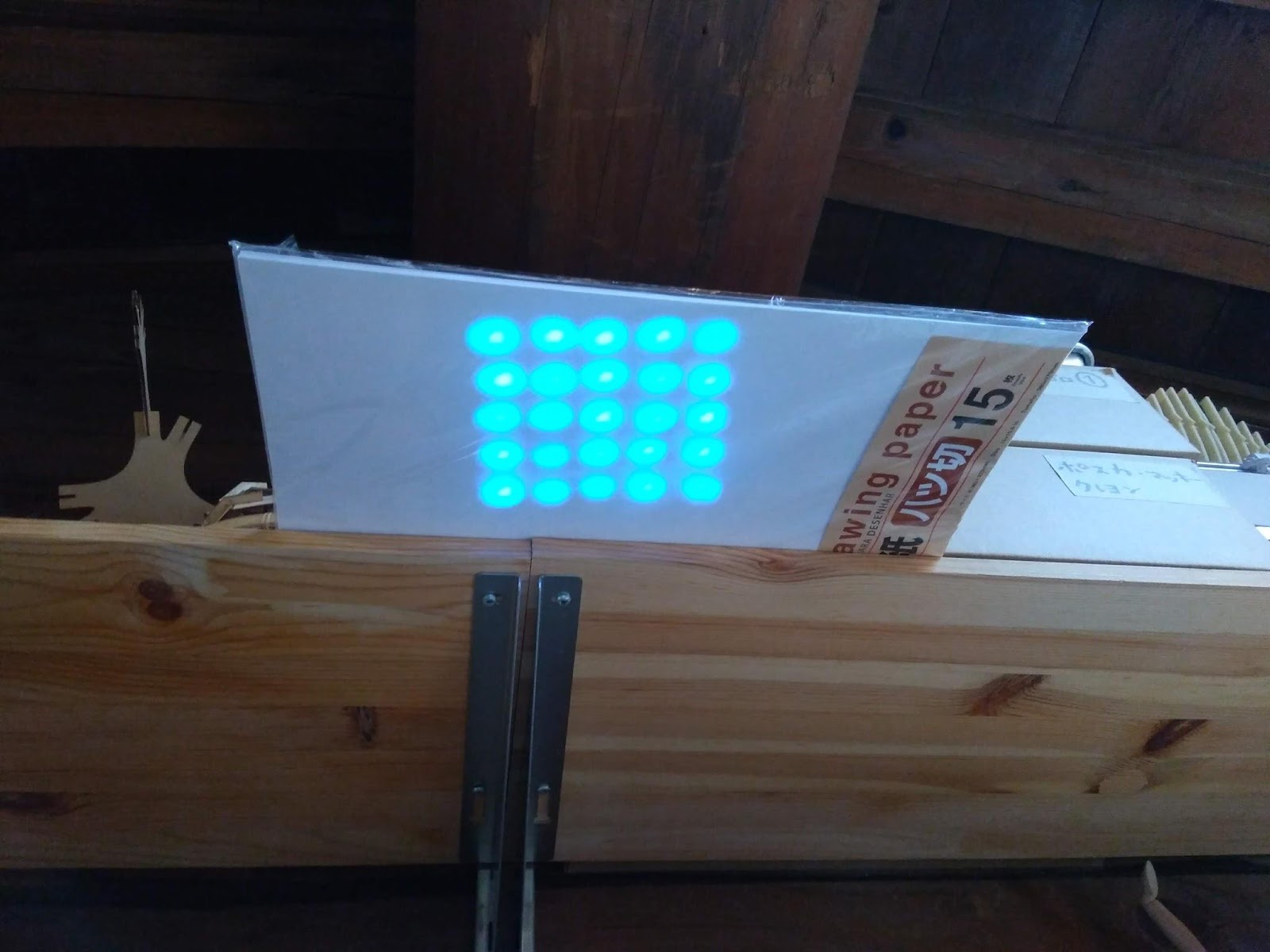
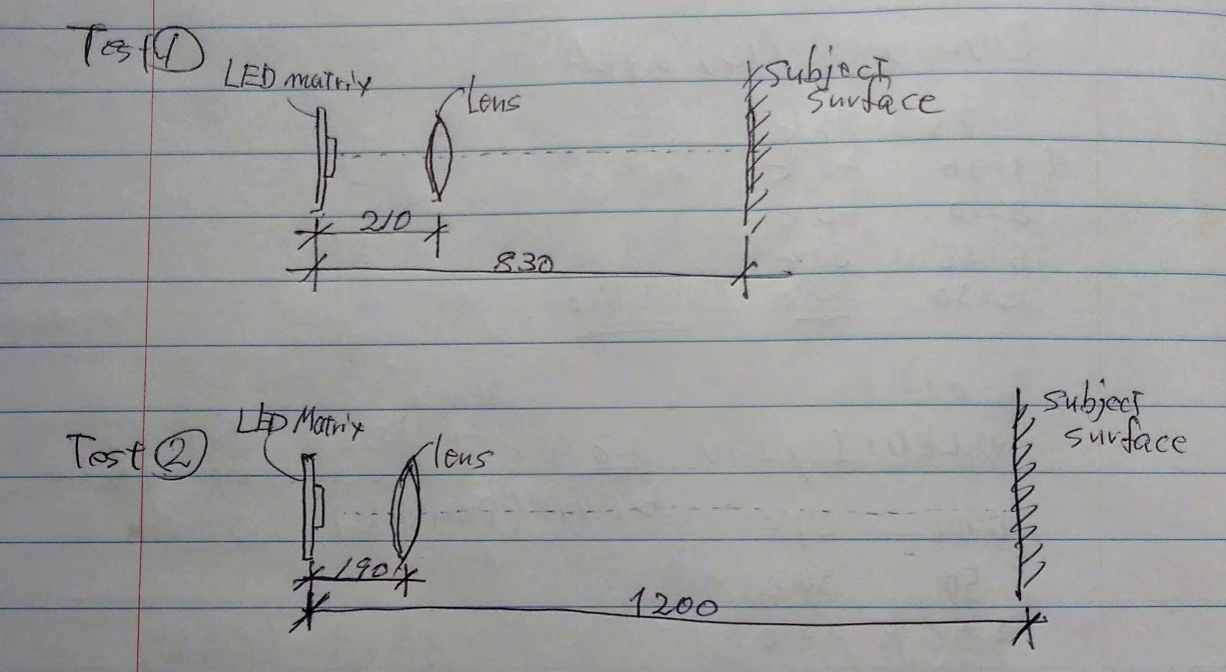
Result
It turned out that I will need 190mm to 210mm(220mm include margin) in usage at around 800mm to 1200mm range.
Issue
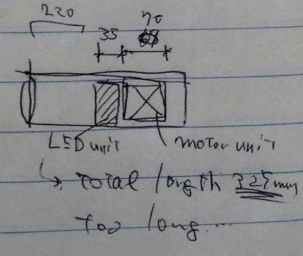
In the design I had at that moment motor unit was taking 70mm length which meant, leaving 220mm in front of the LED board, total length of the light will be 325mm. It took too much space.
Later I fixed the design (current design on June 6th) to fit motor unit to15mm and succeeded to keep total length within 250mm while ensuring moving parts (LED unit and motor unit) to back off satisfying distant from the lens.
Final result
In the final version of Protolight, rack and pinion failed. As servo rotates, LED unit slants, eventually pulleys and gears get stuck.
I am assuming that this is caused by too narrow space between front and back pulley that could not keep back slanting LED unit, also I could have used two pinions at the top and the bottom connected directly to servo so that pinions equally push the unit forward.
Anyway, I kept rack and pinion and used it as a fixation mean of LED unit while adjusting the focal length manually with hand.
References
Making closed loop on rack and pinion mechanism
http://fabacademy.org/archives/2014/students/heren.jeanbaptiste/index.html?week=14
Inkscape plugin for rack and pinion
http://archive.fabacademy.org/2017/fablabkitakagaya/students/200/assignment09.html
3Dprint
Duct rail drawings