Week11 : Input Devices
Group Work
Group assignmet is here
Temperature sensor
Design
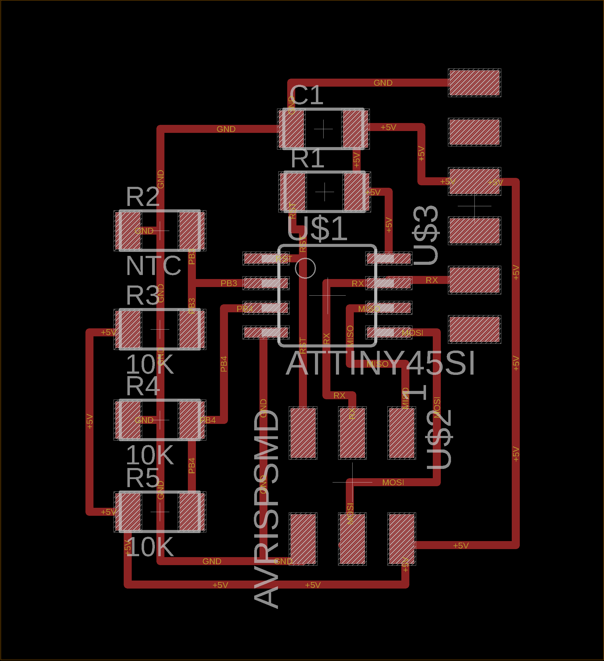
I designed temperature sensor board refering to the Neil's example, at first.

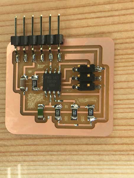
I download example (c file and makefile and python file) and wrote the programe to the made bord.
Following pictures are the temperature sensor that I used(NHQ103B375T10) and its datasheet.
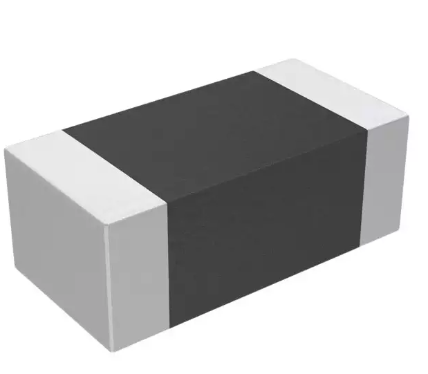
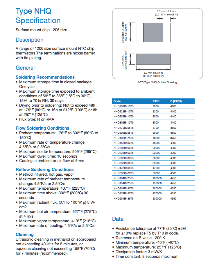
That temperature sensor is called NTC thermistor. The NTC thermistor is an electronic component whose resistance value varies with temperature change, when the temperature rises, the resistance decreases.


I download example (c file and makefile and python file) and wrote the programe to the made bord.
Following pictures are the temperature sensor that I used(NHQ103B375T10) and its datasheet.


That temperature sensor is called NTC thermistor. The NTC thermistor is an electronic component whose resistance value varies with temperature change, when the temperature rises, the resistance decreases.
Needed parts
- ATTiny 45 microcontroller (1 piece)
- Capacitor 1uF (1 piece)
- Resistor 10K ohm (4 piece)
- Resistor 1K ohm (1 piece)
- 6 pin header (1 piece)
- 6 pin header for FTDI (1 piece)
- temperature sensor 235-1109-1-ND (1 piece)
Check with Example Program
Programing
Next, I tried to wrote programe with Arduino IDE.
When attiny45 used, Serial could not be used. So if we want to use serial communication, we have to include SoftwareSerial library.
I used PB2 pin for output and PB3 pin for input from temperature sensor, these pins correspond to pin 2,3 in Arduino pins.


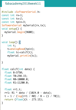
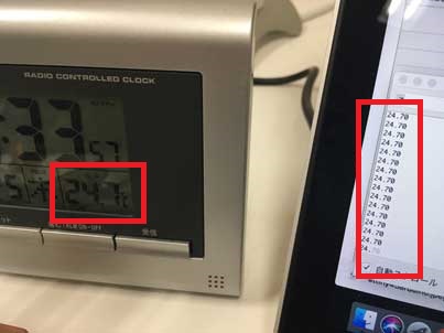
It worked well. When the varialble R1 is changed as above, the sensor measured actual temperature.
But it use 98% flash memry of ATtiny45.

When I addedd delay command, with just this command, it exceeded the capacity of the flash memory. The ROM size of ATtiny45 is only 4K byte.
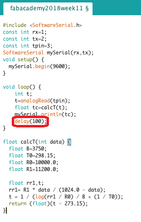

I understood that the program that written in microchip should have minimum function.
When attiny45 used, Serial could not be used. So if we want to use serial communication, we have to include SoftwareSerial library.
I used PB2 pin for output and PB3 pin for input from temperature sensor, these pins correspond to pin 2,3 in Arduino pins.


It worked well. When the varialble R1 is changed as above, the sensor measured actual temperature.

But it use 98% flash memry of ATtiny45.

When I addedd delay command, with just this command, it exceeded the capacity of the flash memory. The ROM size of ATtiny45 is only 4K byte.


I understood that the program that written in microchip should have minimum function.
Files
Files can be downloaded from here
Temperature sensor for final project
Thermocouple (Temperature Sensor)
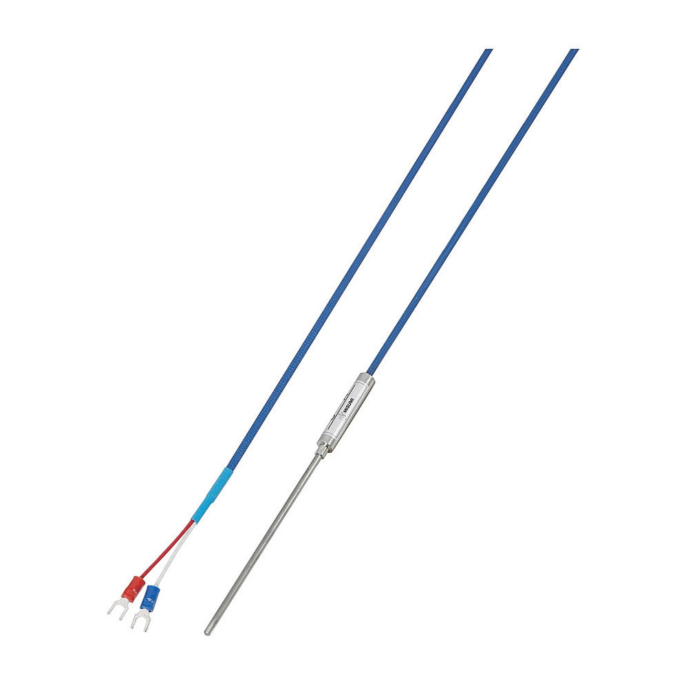
In my final projeect, temperature sensor that can sensing 350℃ will be needed. Thermocouple meets that condition. I selected the thermocouple that can measure 0-650℃ by reading several thermocouple datasheet.
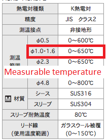
So, I tried to make thermocouple sensor board.
Amplifier chip for Thermocouple
Since the output of the thermocouple is very small, it needs to be amplified by the amplifier before AD conversion processing. I used MAX31855 for amplifier.
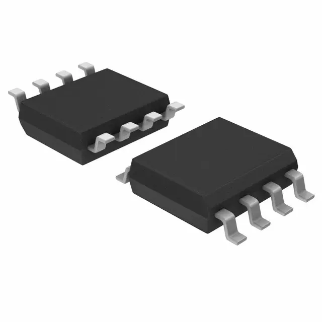
But there was a problem that MAX31855's Power-Supply Voltage was 3.3V. So, it was necessary to lower the voltage from 5V to 3.3V. Following table is Max31855 recommended operating conditions described in the datasheet.

This circuit diagram was very difficult for me. So, Fablab Staff Mr. Yamamoto hepled me. At first, we decided to divide the sensor board and master board to limit the scope of the problem.

But there was a problem that MAX31855's Power-Supply Voltage was 3.3V. So, it was necessary to lower the voltage from 5V to 3.3V. Following table is Max31855 recommended operating conditions described in the datasheet.

This circuit diagram was very difficult for me. So, Fablab Staff Mr. Yamamoto hepled me. At first, we decided to divide the sensor board and master board to limit the scope of the problem.
Test for using thermocouple
Following pictures are schematic & board of master board.
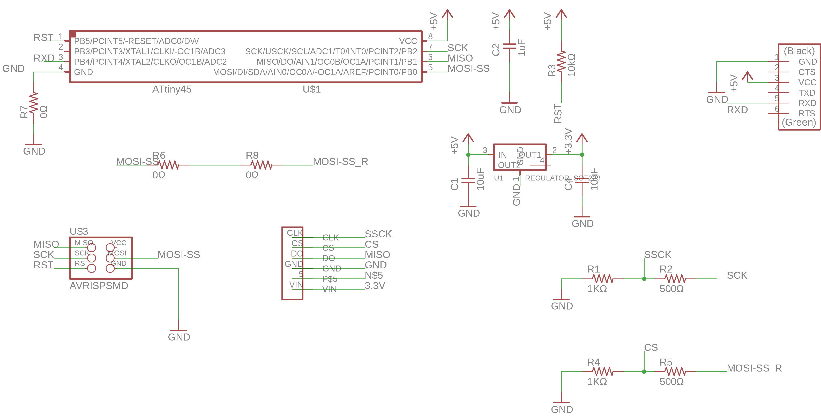
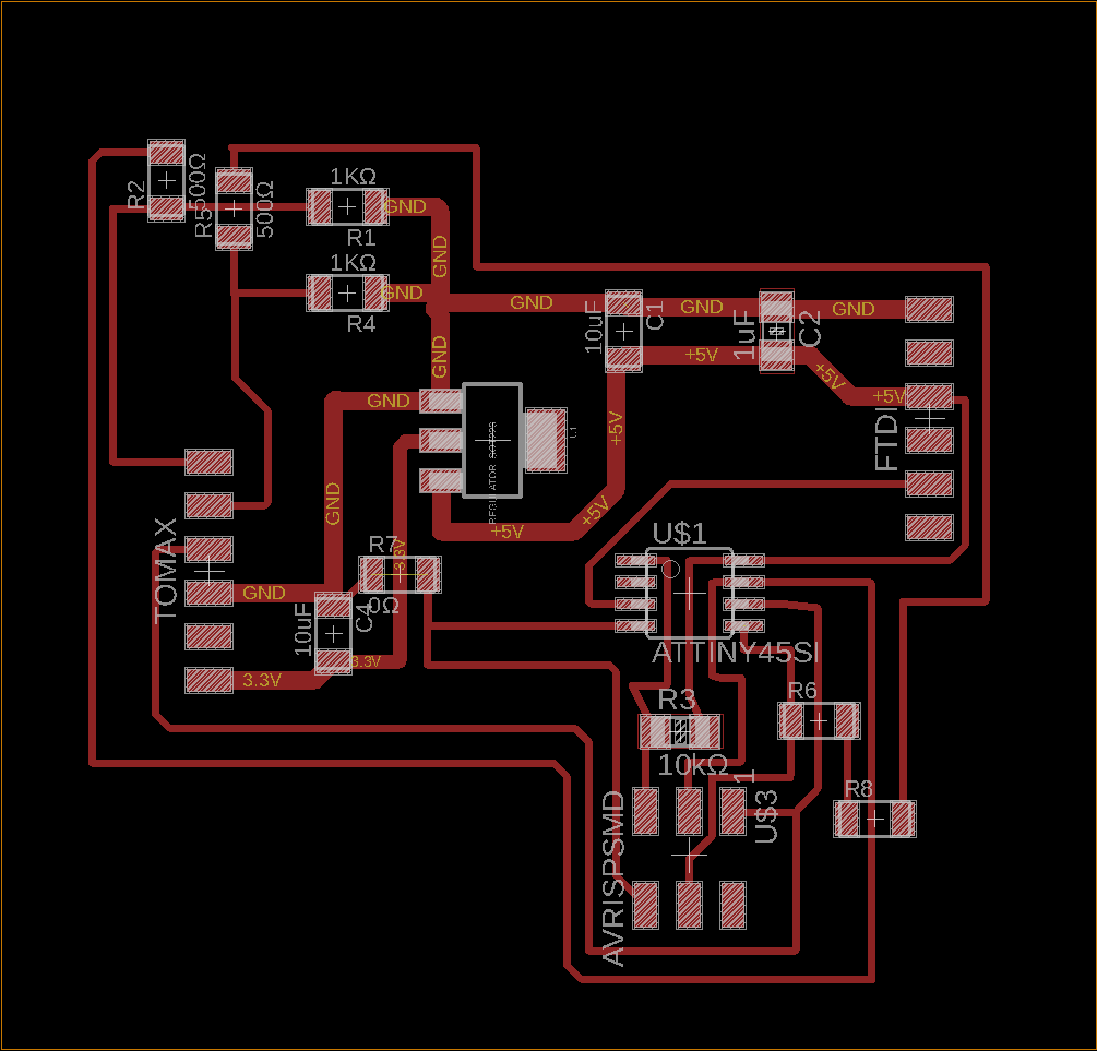
Following pictures are schematic & board of sensor board.
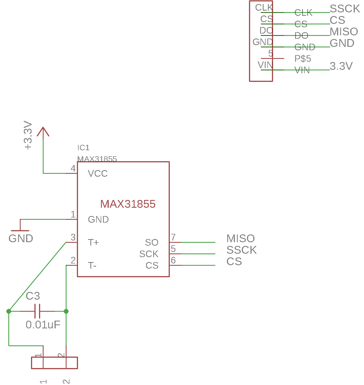
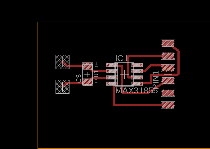
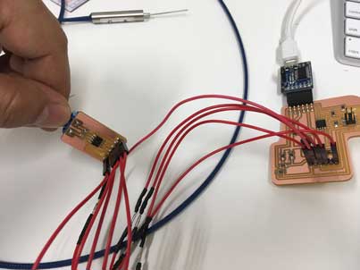


Following pictures are schematic & board of sensor board.


Change library for controll MAX31855
There is the max31855 library for Arduino. But it uses SPI lirbrary. That SPI library doesn't work with ATtiny45. I found tinySPI library and modify the max31855 library with tinySPI library.
High Temperature
I measured the temperature of soldering iron. This sensor can sense high temperature !
On Board
Finally I combined sensor board and master board.
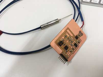
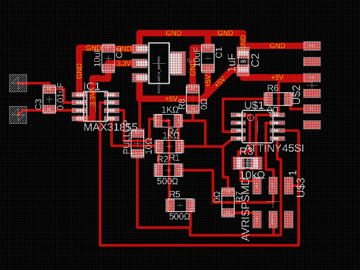
Pull up register is needed only for write the program to microchip at first time, in order to avoid disturbing program writing by communication with the max31855.


Pull up register is needed only for write the program to microchip at first time, in order to avoid disturbing program writing by communication with the max31855.
Needed parts
- ATTiny 45 microcontroller (1 piece)
- Capacitor 1uF (1 piece)
- Capacitor 10uF (2 piece)
- Resistor 10K ohm (4 piece)
- Resistor 1K ohm (2 piece)
- Resistor 500 ohm (2 piece)
- Resistor 0 ohm (3 piece)
- 6 pin header (1 piece)
- 6 pin header for FTDI (1 piece)
- Regulator 3.3V(1 piece)
- Amplifier Max31855(1 piece)
- Thermocouple Type K(1 piece)
Files
Files can be downloaded from here
