Week6 : 3D Scanning and Printing
Test the design rules for your 3D printer(group)
Our lab's 3D printer is AFENIA H480
We leaned how to use AFENIA H480 and tested its design rules.
The accuracy of the cylinder was -0.05 to -0.25 mm
Comparing holes and cylinders designed with the same size, the cylinder tended to print smaller.
As a result of the experiment, it was expected to combine the holes and the cylinder even if they were made with the same size. I tried it, it was quite tight(It could't move), but it could to be combined.
I understand that it is good to design with a difference of about 0.5 mm when making movable parts to be assembled from the results of experiments.
Group assignment(including another test) is discribed group page.
We leaned how to use AFENIA H480 and tested its design rules.
- How to use AFENIA slicer.
- Experiment: How accurately our 3D printer could print. First we make test board, it's have 3 holes(3mm, 5mm, 7mm) and 3 cylinder(3mm, 5mm, 7mm). The pourpose of this board is that I wanted to know how much leeway should be given to the combination part in order to make things in a state of combining two parts with a 3D printer.
- 3mm hole ->2.95mm
- 5mm hole ->4.9mm
- 7mm hole ->6.8mm
- 3mm cylinder ->2.95mm
- 5mm cylinder ->4.75mm
- 7mm cylinder ->6.75mm
Result is follows
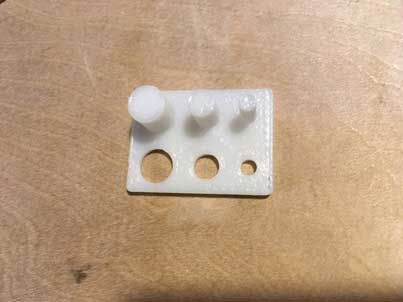
The accuracy of the cylinder was -0.05 to -0.25 mm
Comparing holes and cylinders designed with the same size, the cylinder tended to print smaller.
As a result of the experiment, it was expected to combine the holes and the cylinder even if they were made with the same size. I tried it, it was quite tight(It could't move), but it could to be combined.
I understand that it is good to design with a difference of about 0.5 mm when making movable parts to be assembled from the results of experiments.
Group assignment(including another test) is discribed group page.
Design and 3D print an object (small, few cm)that could not be made subtractively (individual)
3D design with Fusion360
I decided to make a tool to water the flowers with plastic bottles. I used Fusion360 for 3D modeling.
After removing the support, I checked if it move.
Step7: Use
■ Why it could not be made subtractively
This parts consists of 2 parts, and it was printed assembled state. These two parts can be made with subtractively each athor, but it could not made assembled sate with subtractively.
■Download
Designed file is here
-
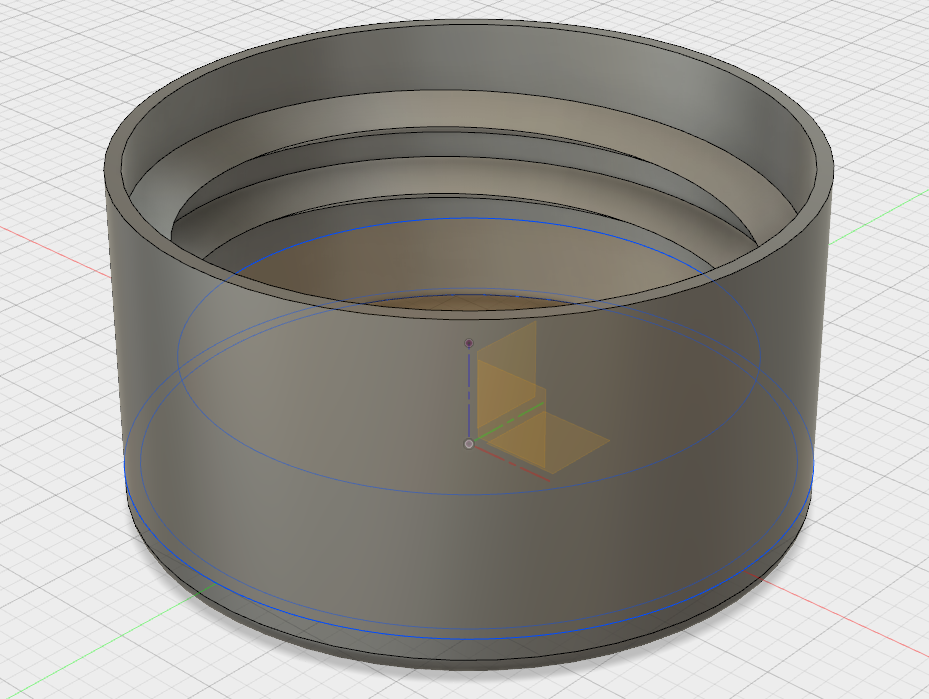
Step1: Design plastic bottle cap.Screw part:diameter 24.9 mm, pitch 3.4mm -

Step1-1: Using Coil funstion for making thread.Coil function can be used
[Create]->[Coil] -

Thead vs Coil
Thread function([Create]->[Thread] ) is useful for making thread that follows the standard.
But in the case of plastic bottle cap, there are no standard for it. So I used Coil function to make the plastic bottle cap thread.
-
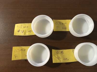
Step2: Test print.Layer thickness, Quality. -

Step3: Assembly checkLayer thickness:0.15 & Quality:Fine seemed good, but Layer thickness 0.3 & Quality:Normal also can be worked.
So, Layer thickness 0.3 & Quality:Normal is enough.
-

Step4-1: Design water function -
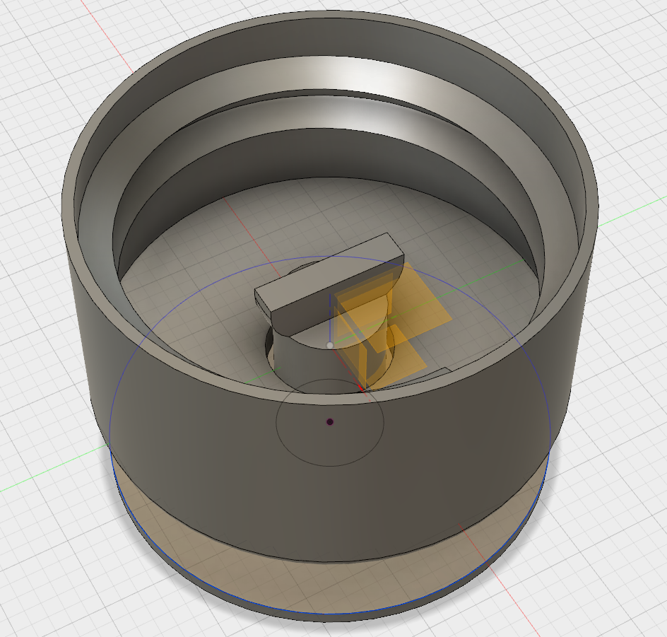
Step4-2: Another view of water function. -
Step4-3:Margin
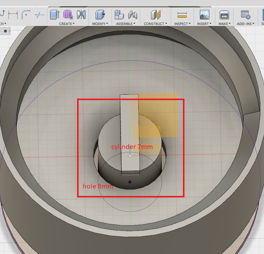
Accoding to design test, 0.5mm margin is enough. But in this case, it need to margin through water passing.So, I designed cylinder 7mm, hole 8mm.
-
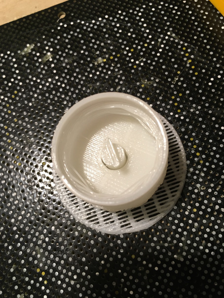
Step5-1: 3D print. -

Step5-2:Support
In this case, because there is a floating part, support was printed. -

Step6: Remove support.
After removing the support, I checked if it move.
Step7: Use
■ Why it could not be made subtractively
This parts consists of 2 parts, and it was printed assembled state. These two parts can be made with subtractively each athor, but it could not made assembled sate with subtractively.
■Download
Designed file is here
3D Scan
3D design
Since I have used Sense 3D scanner, I wanted to use other one. I scanned with i-phone app
Trnio.

After open Trnio app, you shoul tap camera icon if you scan with iphone camera.

Tap the screen to start scanning.
Move the iphone slowly, the photos are took automaticaly.


After taking the picture, tap the menu icon and the Queue. You can see the list of you have scanned.


If you tap the picture that you want to edit, you can see that screen. In that screen, you can trim and publish to Sketchfab.
The 3D scanner of the application was easier to use than expected.
【Problem】 If the surroundings is not bright ennough, it will not be able to scan well.The following is the result of scanning with bright one side because only light was applied from one direction. As you can see, only one side had been scanned. Therefore, the mouse scan shown above was done in a bright place.
【Sense 3D scanner】
I noticed that using Tnrio can not be a stl file. So, I scanned with Sense 3D scanner.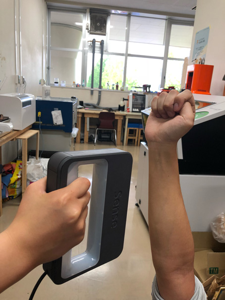
Next, scanned data was cut in half with meshmixer.
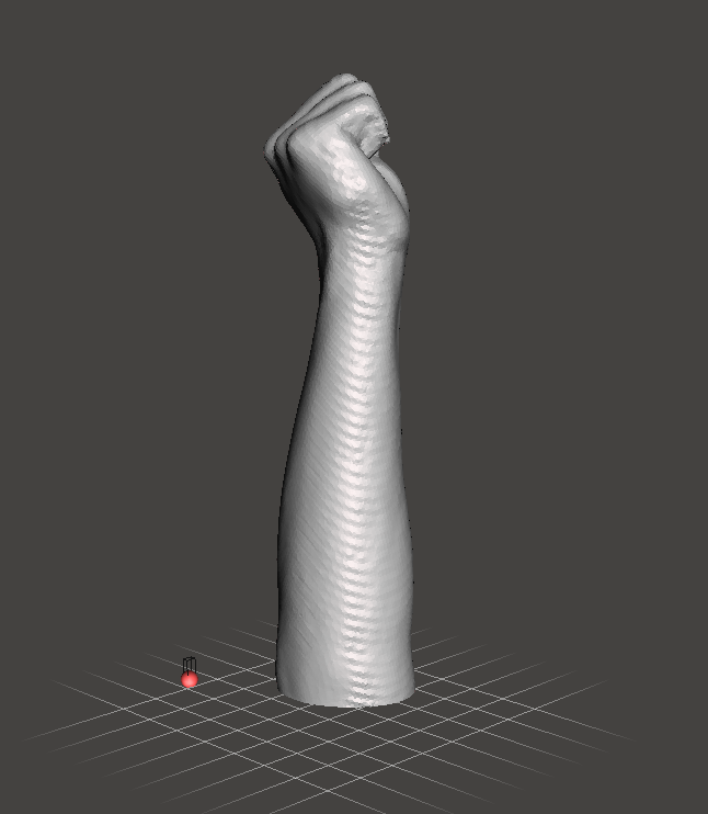

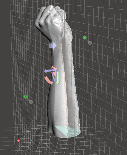
Export to stl file.


Following picture is the mold that made with 3D printer.


After open Trnio app, you shoul tap camera icon if you scan with iphone camera.

Tap the screen to start scanning.
Move the iphone slowly, the photos are took automaticaly.


After taking the picture, tap the menu icon and the Queue. You can see the list of you have scanned.


If you tap the picture that you want to edit, you can see that screen. In that screen, you can trim and publish to Sketchfab.

The 3D scanner of the application was easier to use than expected.
【Problem】 If the surroundings is not bright ennough, it will not be able to scan well.The following is the result of scanning with bright one side because only light was applied from one direction. As you can see, only one side had been scanned. Therefore, the mouse scan shown above was done in a bright place.
【Sense 3D scanner】
I noticed that using Tnrio can not be a stl file. So, I scanned with Sense 3D scanner.

Next, scanned data was cut in half with meshmixer.


Export to stl file.


Following picture is the mold that made with 3D printer.

Files (all file-->zip)
All files can be downloaded form here
