Week5 : Electronics Production
PCB production process(group)
I learned PCB production process in the group work.
- How to use milling machie(Roland DG SRM-20).
- How to flatten the surface of the sacrificial borad.
- How do aftertreatment with our equipment.
- Experiment: How much width can be processed by 1/64 end mill (Our lab don't have 1/1000 end mill)
- 0.02mm(1/1000 inch) was the minimum line thickness
- 0.4mm(16/1000 inch) was the minimum for the gap between lines.
ISP (individual)
What is AVR
AVR is a generic term for the 8bit micro controller product family manufactured by Atmel.(Atmel is American company.)
AVR has 2 series, ATtiny and ATmega. ATtiny has 8~20pin and small and cheap. ATmega has more than 20pins, and it is high performance but expensive.Even if it is expensive, it costs about a few dollars.
Following table shows spec of some type of ATtiny products.
RAM:Random Access Memory
ROM:Read Only Memory
AVR has 2 series, ATtiny and ATmega. ATtiny has 8~20pin and small and cheap. ATmega has more than 20pins, and it is high performance but expensive.Even if it is expensive, it costs about a few dollars.
Following table shows spec of some type of ATtiny products.
| name | PIN | RAM | ROM | analog in | digital in-put | internal clock | PWM | timer |
| ATTiny13A | 8 | 64byte | 1Kbyte | 4 | 6 | 9.6MHz | 2 | 1(8bit) |
| ATTiny44A | 14 | 256byte | 4Kbyte | 8 | 12 | 8MHz | 4 | 2(8bit×1 + 16bit×1) |
| ATTINY45 | 8 | 256bytes | 4Kbyte | 4 in | 6 | 16.5MHz | 4 | 2(8bit) |
| ATTiny85 | 8 | 512byte | 8Kbyte | 4 in | 6 | 16.5MHz | 4 | 2(8bit) |
ROM:Read Only Memory
What is ISP
In System Program
ISP(In System Program) is to write a program to a micro controller after mounting it on an electronic circuit board. The advantage of this method is that there is no need to separately provide a writing step before assemble.
AVR is ISP micro controller.
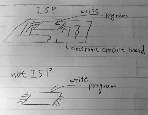
AVR is ISP micro controller.

In System Programmer or ISP programmer or AVR witer or AVR programmer
ISP(In System Programmer) means AVR writer that write programe to ISP micro controller like AVR. There are resemble word like ISP programmer or AVR witer or AVR programmer in web pages, these word has same meaning. I confused at first.
Parts
I decided to make "hello.ISP.44.res".
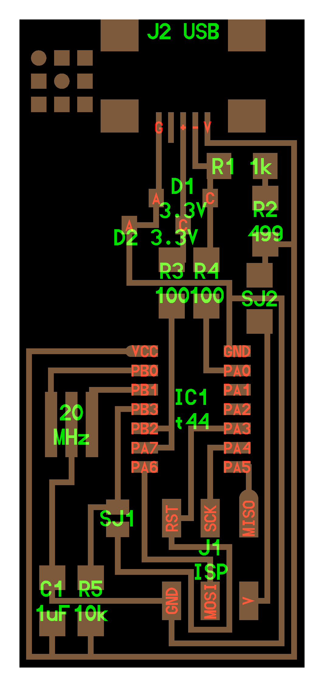
Needed parts is follows.

Needed parts is follows.
- ATTiny 44 microcontroller (1 piece)
- Capacitor 1uF (1 piece)
- Resistor 100 ohm (2 piece)
- Resistor 499 ohm (1 piece)
- Resistor 1K ohm (1 piece)
- Resistor 10K (1 piece)
- 6 pin header (1 piece)
- USB connector (1 piece)
- jumpers - 0 ohm resistors (1 piece)
- Zener Diode 3.3 V (2 piece)
- Resonator 20MHZ(1 piece)
- usb mini cable (1 piece)
- ribbon cable (1 piece)
- 6 pin connectors (attached to ribbon cable)(2 piece)
■Zener Diode Function
Normal diode works to prevent backflow of current.
But, Zener diode is the element that used for obtaining a constant voltage. This is the function that utilize the property that reverse current flows when apllying a certain voltage to zener diode.So, zener diode is mounted in the opposite direction to the ordinary diode.
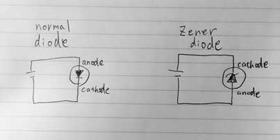
But, Zener diode is the element that used for obtaining a constant voltage. This is the function that utilize the property that reverse current flows when apllying a certain voltage to zener diode.So, zener diode is mounted in the opposite direction to the ordinary diode.

■Capacitor Function
The capacitor has the function of stabilizing voltage and removing noise.
■Registor Function
The resistor resist the flow of electricity and has the role of adjusting to the current corresponding to the circuit.
We must pay attention to the description of the chip resistance code.
【In the case of normal number】
Last digit means multipulier of powe of ten. To put it simply, last digit means how many zeros to add.
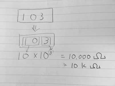
113 -> 11×103 =11kΩ
112 -> 11×102 =1.1kΩ
【In the case of including ”L” code】
Replace L with mΩ
11L =11mΩ
1L1 =1.1mΩ (If L is in the middle digit, Replace L to decimal point and mΩ)
10L5=10.5mΩ
【In the case of including ”R” code】
Replace R with decimal point
1R5 =1.5Ω
2R15=2.15Ω
We must pay attention to the description of the chip resistance code.
【In the case of normal number】
Last digit means multipulier of powe of ten. To put it simply, last digit means how many zeros to add.

113 -> 11×103 =11kΩ
112 -> 11×102 =1.1kΩ
【In the case of including ”L” code】
Replace L with mΩ
11L =11mΩ
1L1 =1.1mΩ (If L is in the middle digit, Replace L to decimal point and mΩ)
10L5=10.5mΩ
【In the case of including ”R” code】
Replace R with decimal point
1R5 =1.5Ω
2R15=2.15Ω
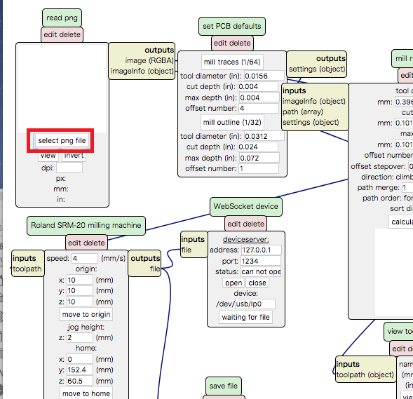
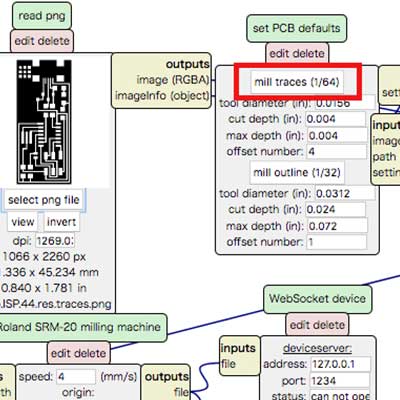
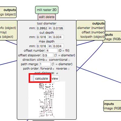
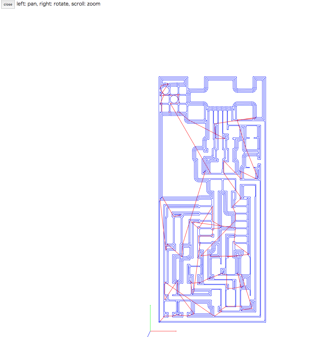
■How to use mods
Circuit data for RolandDG SRM-20(rml format file)
Using this png file.
-
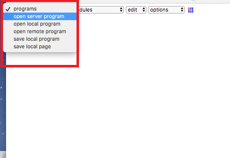
Step1: [programns] -> [open server program] -
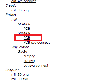
Step2: select [Roland]->[SRM-20]->[PCB] -
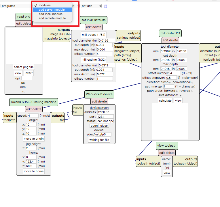
Step3: [modules] -> [add server module]
-

Step4: select [file]->[save] -
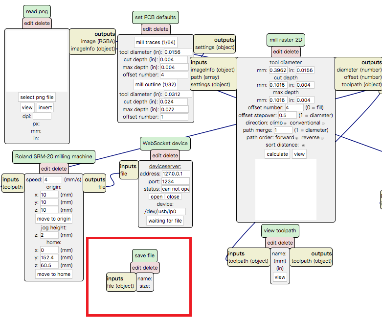
Step5: drag and drop the green part of the [file save module] and place it beside [Roland SRM - 20 milling machine module]. -
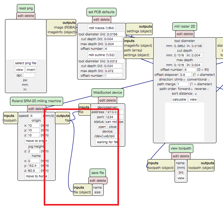
Step6: click on the inputs in the [file save module] and then click on the [Roland SRM - 20 milling machine] 's outputs, two will be connected.
Interior data for RolandDG SRM-20(rml format file)
Using this png file.
Process is almost same except Step8. It should be select [mill outline(1/32)]. Difference is only this!
Process is almost same except Step8. It should be select [mill outline(1/32)]. Difference is only this!
■Milling
-
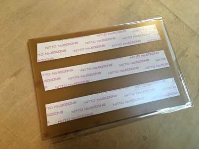
Step1: set FR1 with double side tape. -
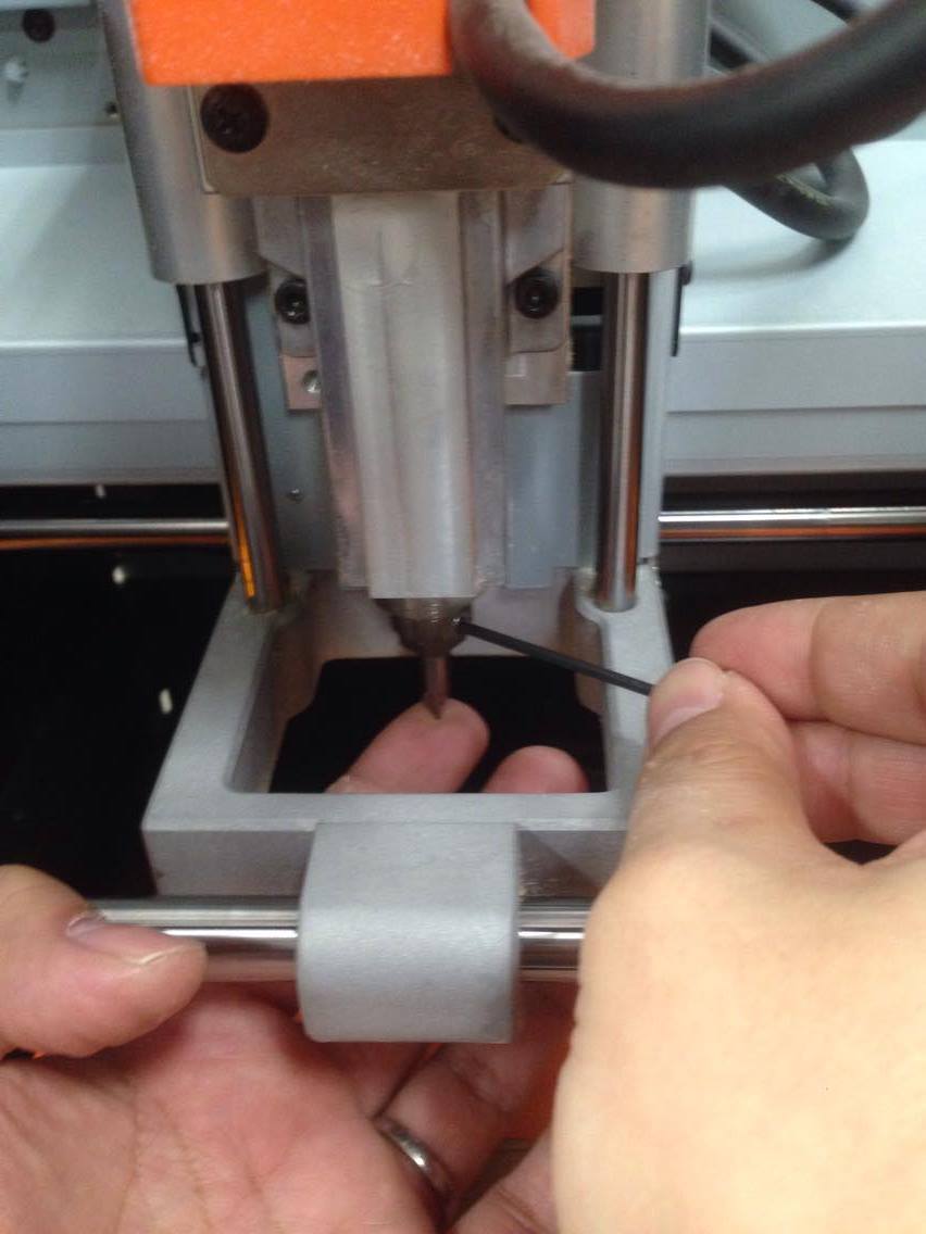
Step2: attaching an endmill -
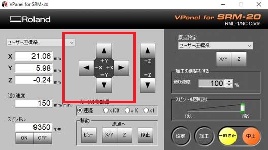
Step3: Activating VPanel.
It moves in XYZ directions with arrow keys.
-
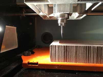
Step4: Adjustment of the origin of XY. -
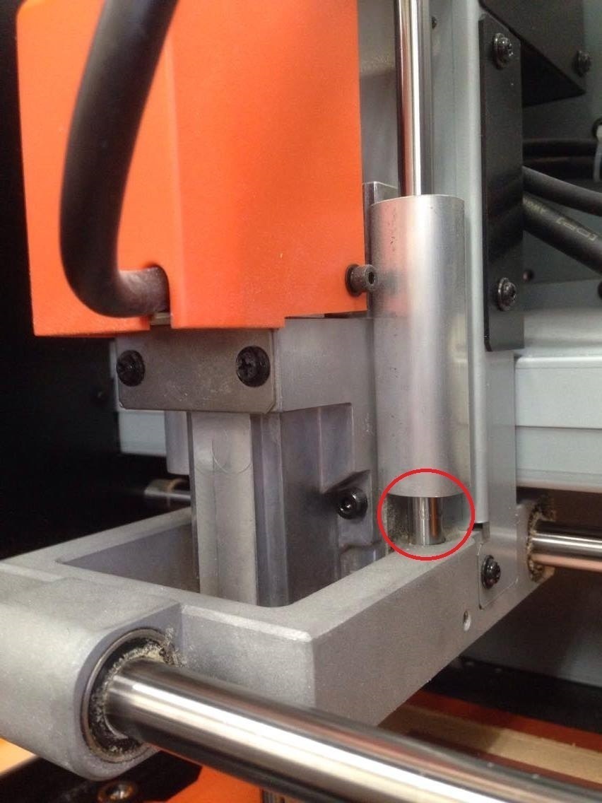
Step5: Adjustment of the origin of Z
Use arrow keys to move endmill close to the substrate. (Be careful that it does not touch the substrate at this point) -
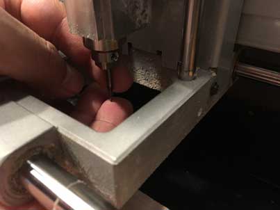
Step6: Use a wrench to loosen the fixation and pull down the endmill manually so that it barely touches the ground.
■Aftertreatment & Soldering
After milling circuit bord with milling machine, aftertreatment is needed as follows.
Solder flux has following effects.
-
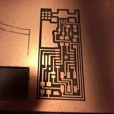
Step1: milling the circuit bord -
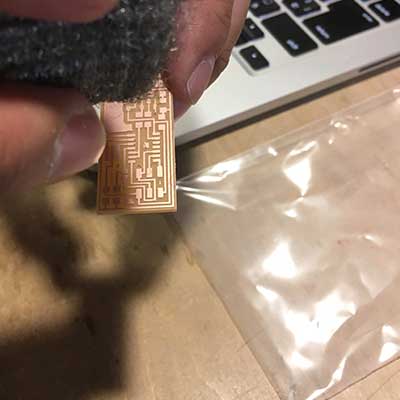
Step2: Deburring with steelwool.If burr is left, there may be unexpected energization. -
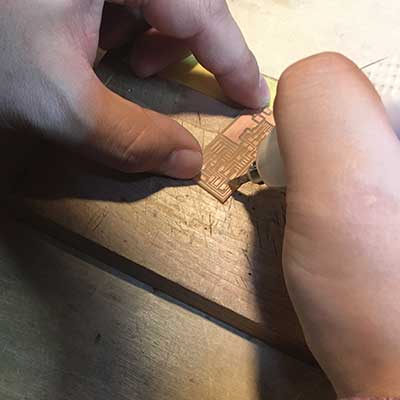
Step3: Remove parts you do not need with a cutter.
-
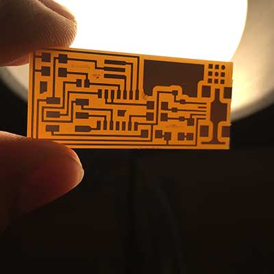
Step4: Check if the unnecessary part is removed. -

Step5: Wash with soap and water. -
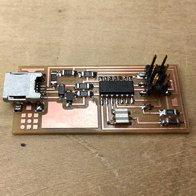
Step6: Soldering the parts
Maybe, it's shiny & smooth !
Solder flux has following effects.
- Remove foreign matter on the surface and oxide film.
- Prevent oxidation of the joint.
■Build
- Install X-code from Mac app store.
- Download crosspack for mac from here and install it. crosspack include avr-gcc, avrdude. avr-gcc is compier, avrdude is writing tool.
- Get FabISP firmware for MacOS10.8.2 from here and move ZIP file to Desktop. (firmware is software for controlling a computer system incorporated in an electronic device)
- Open terminal and the following command is excuted.(For the subsequent procedures, refer to the procedure described here.)
$ cd desktopfollowing files were included.
$ unzip fabISP_mac.0.8.2_firmware.zip
$ cd fabISP_mac.0.8.2_firmware
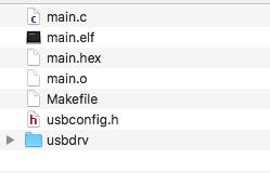
Makefile is a text file that describes rules such as compiling and installing e.t.c.
- Connect ISP and AVR writer and PC
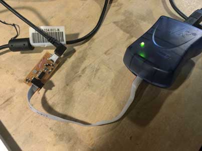
- I used AVR ISP2 programmer, so I didn't need to edit Makefile. But if we use another ISP programmer, we have to edit following part of Makefile with texteditor.
AVRDUDE = avrdude -c avrisp2 -P usb -p $(DEVICE) # edit this line for your programmer
- Input following command. This commandd means execute "clean" target written in Makefile.
$ make cleanIn Makefile, clean target is wrote like follows.

following message was shown, it was success!rm -f main.hex main.lst main.obj main.cof main.list main.map main.eep.hex main.elf *.o usbdrv/*.o main.s usbdrv/oddebug.s usbdrv/usbdrv.s - Input following command. This commandd means execute "hex" target written in Makefile.
$ make hexIn Makefile, hex target is wrote like follows.

following message was shown, it was success!avr-gcc -Wall -Os -DF_CPU=20000000 -Iusbdrv -I. -DDEBUG_LEVEL=0 -mmcu=attiny44 -c usbdrv/usbdrv.c -o usbdrv/usbdrv.o
avr-gcc -Wall -Os -DF_CPU=20000000 -Iusbdrv -I. -DDEBUG_LEVEL=0 -mmcu=attiny44 -x assembler-with-cpp -c usbdrv/usbdrvasm.S -o usbdrv/usbdrvasm.o
avr-gcc -Wall -Os -DF_CPU=20000000 -Iusbdrv -I. -DDEBUG_LEVEL=0 -mmcu=attiny44 -c usbdrv/oddebug.c -o usbdrv/oddebug.o
avr-gcc -Wall -Os -DF_CPU=20000000 -Iusbdrv -I. -DDEBUG_LEVEL=0 -mmcu=attiny44 -c main.c -o main.o
main.c:88:13: warning: always_inline function might not be inlinable [-Wattributes]
static void delay ( void )
^
avr-gcc -Wall -Os -DF_CPU=20000000 -Iusbdrv -I. -DDEBUG_LEVEL=0 -mmcu=attiny44 -o main.elf usbdrv/usbdrv.o usbdrv/usbdrvasm.o usbdrv/oddebug.o main.o
rm -f main.hex main.eep.hex
avr-objcopy -j .text -j .data -O ihex main.elf main.hex
avr-size main.hex
text data bss dec hex filename
0 2002 0 2002 7d2 main.hex
- Input following command. This commandd means execute "fuse" target written in Makefile.
$ make fuseIn Makefile, fuse target is wrote like follows.

fuse is the bits of parameters that sets AVR chip operation.
fuse setting items are as follows, but I do not understand the contents.
following message was shown, it was success!name function RSTDISBL Reset pin prohibited DWEN Debug Wire function permission SPIEN Serial programming permission WDTON Watchdog timer Always active BODLEVEL Low voltage reset voltage level CKDIV8 Outgoing clock divided by 8 CKOUT CPU clock output from CLK0 pin SUT_CKSEL Reset delay time setting ・・・・
・・・・
・・・・
avrdude: verifying ...
avrdude: 1 bytes of lfuse verified
avrdude: safemode: Fuses OK (H:FF, E:DF, L:FF)
avrdude done. Thank you.
- Input following command. This commandd means execute "program" target written in Makefile.
$ make programfollowing message was shown, it was success!
・・・・
・・・・
・・・・
avrdude: verifying ...
avrdude: 1 bytes of lfuse verified
avrdude: safemode: Fuses OK (H:FF, E:DF, L:FF)
avrdude done. Thank you.
- Verifing my ISP programmer is working
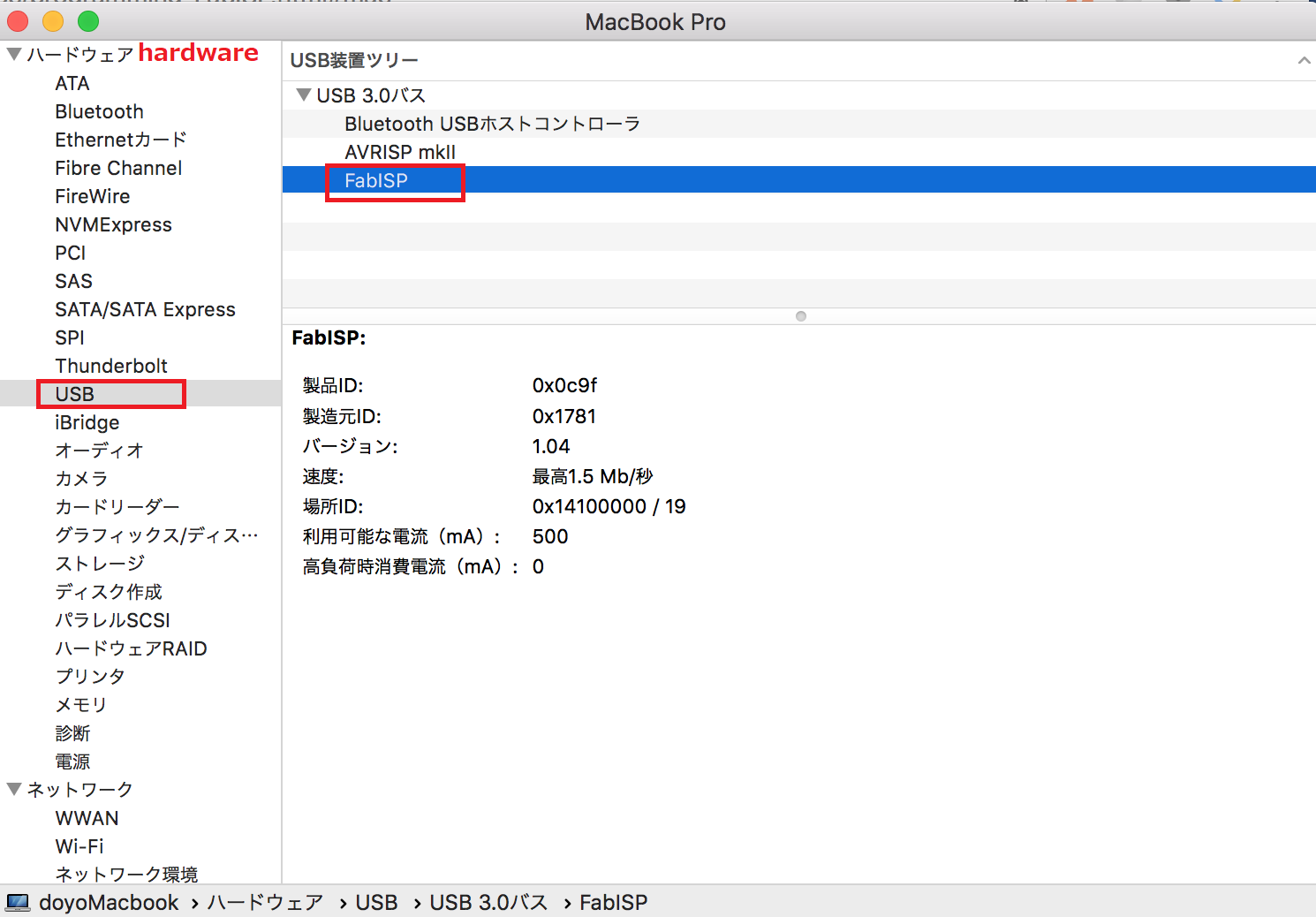
- Remove the jumpers
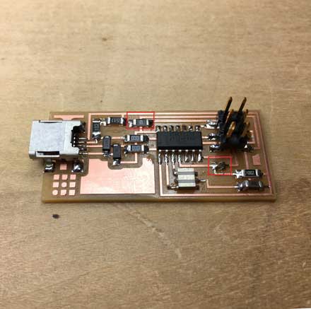
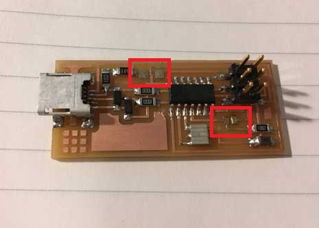
After remove jumpers this board should be used for ISP programmer.
Files
rml format files can be downloaded from here.

