Our laser cutter is Trotec Speedy 100 30W(CO2 laser cutter). It's exhaust system(Atomos) removes dust and gas and filters smell through its carbon filters.First we conducted an experiment to understand the proper parameters for press-fit.
First we conducted an experiment to understand the proper parameters for press-fit. Our group work is here.
Design software: Fusion360
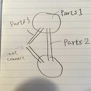
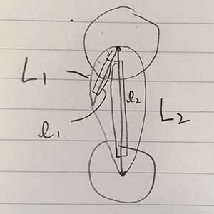
Before design with Fusion360, I thought about what the parts should I make with notebook.Main parts is only three.
big picture
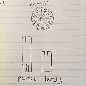
shape of parts
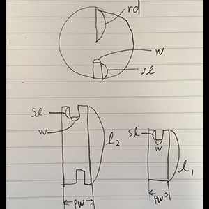
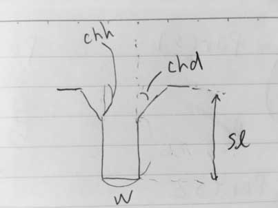
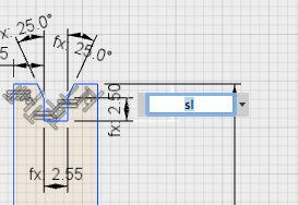
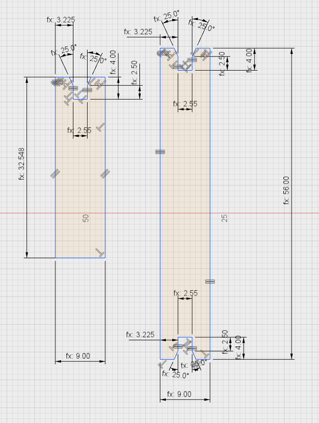
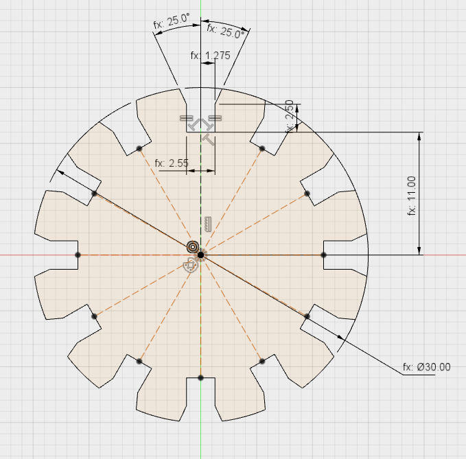
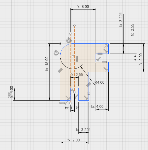
parameter-1
parameter-2
parameter-champer all slot has champer
Thinking with the parametric thinking, 12 parameter is exist in my design, and if 6 parameters is inputted remaining 6 parameter is will be calculated.
※ pw(parts width) is defined as 3 times as t (material thickness) by myself.
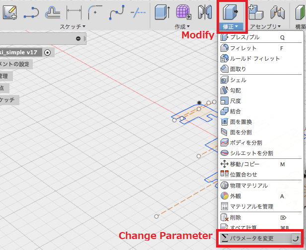
Parametric Design with Fusion360
set parameter
[Modify]->[Change Parameter]
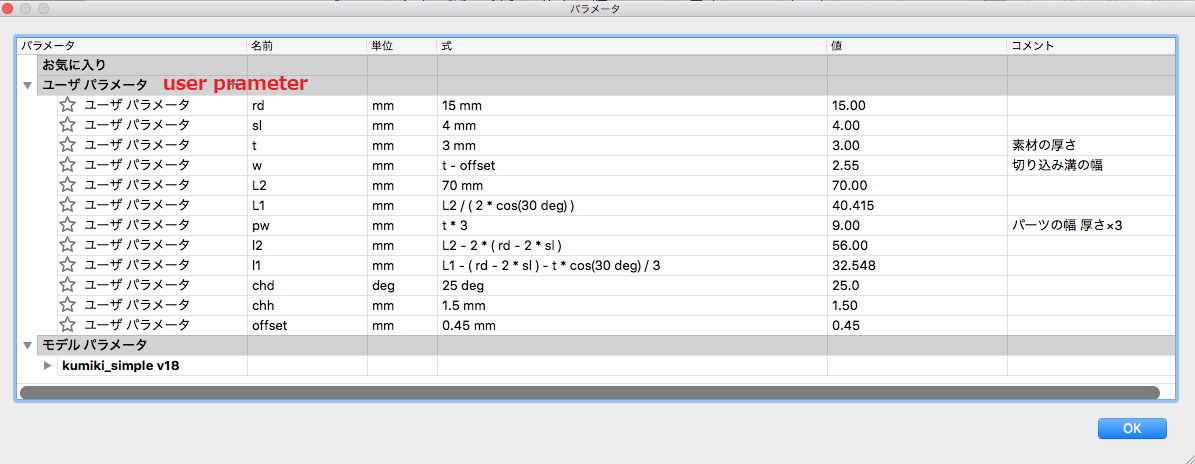
set the parameters as follows. It can be allowed to input formula or value.
input the parameters as follow
If set value is change, other related value, set by formula will be changed. It is very useful and fabulouse !
Additional parts(parts for standing or changing direction)
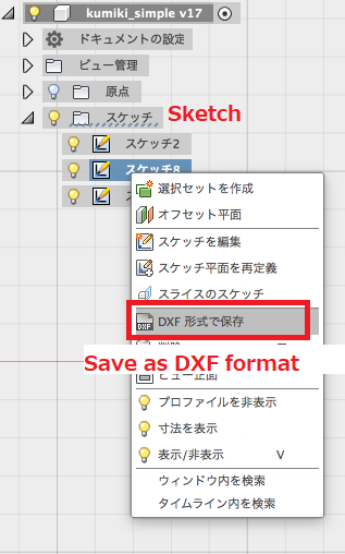
Export to DXF format
[select sketch]->[right clich]->[save as DXF format]
Laser cut
Test Cut
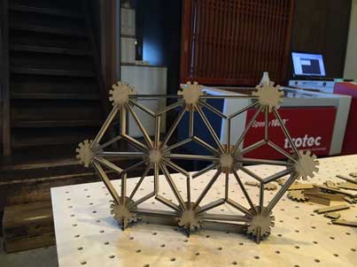
I did test cut with my design. It seemed good.
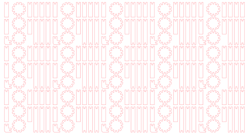
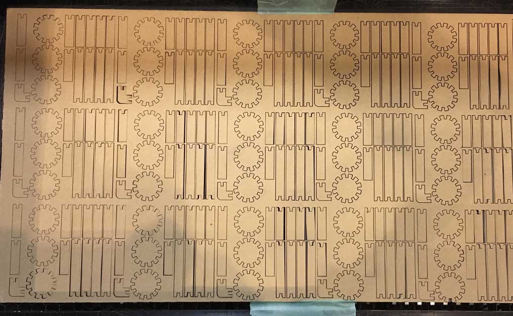
Blueprint for lot fabrication.
The data of each part was arranged as follows for lot fabrication with Illustrator.
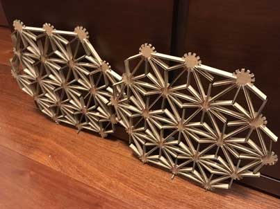
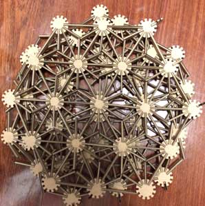
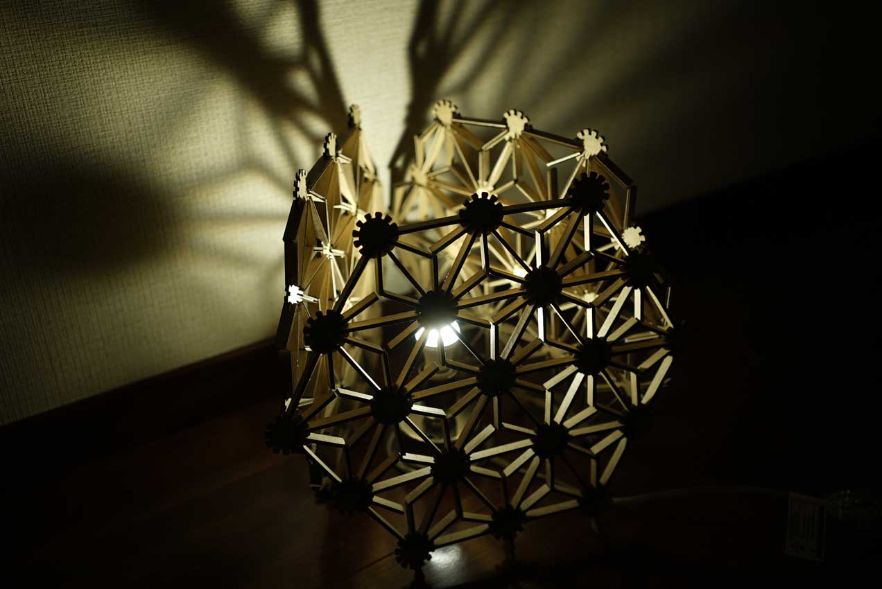
Assembly
I assembled parts in the middle of the night. It took long time...
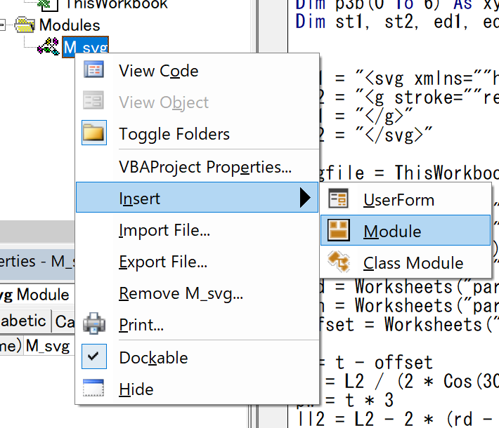
I understood svg file is simple text file last week.So I tried parametric design with programing.(Scad is good but I'm familier with Microsoft Excel VBA, so I tried to create it with VBA.)
VBA (windows)
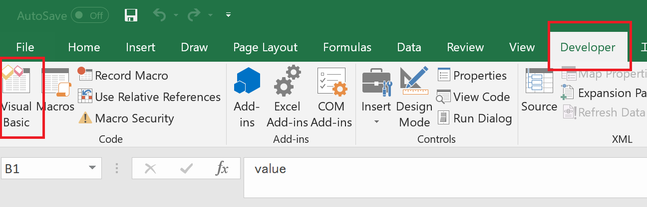
We can program Excel with Visual Basic for Applications(VBA). VBA can be used from visual basic icon in Developer tag
If we click VisualBasic icon we can see the window as below. Then, insert the module [Insert]->[Module]. After making the module.
I wrote the program as below.
Type xy_elements
    x As Double
    y As Double
End Type

Sub pressfit_svg()
Const prt1_pc = 10
Const prt2_pc = 16
Const prt3_pc = 72

Dim rd, sl, t, w, L2, L1, pw, ll2, ll1, chd, chh, offset
Dim p1(0 To prt1_pc) As xy_elements
Dim p2(0 To prt2_pc) As xy_elements
Dim p3(0 To prt3_pc) As xy_elements
Dim p3b(0 To 6) As xy_elements
Dim st1, st2, ed1, ed2


st1 = "<svg xmlns=""http://www.w3.org/2000/svg"" version=""1.1"" width=""100mm"" height=""200mm"" viewBox=""0 0 100 200"">"
st2 = "<g stroke=""red"" stroke-width=""0.5"">"
ed1 = "</g>"
ed2 = "</svg>"

svgfile = ThisWorkbook.Path & "\test.svg"

rd = Worksheets("par").Cells(2, 2)
sl = Worksheets("par").Cells(3, 2)
t = Worksheets("par").Cells(4, 2)
L2 = Worksheets("par").Cells(5, 2)
chd = Worksheets("par").Cells(6, 2)
chh = Worksheets("par").Cells(7, 2)
offset = Worksheets("par").Cells(8, 2)

w = t - offset
L1 = L2 / (2 * Cos(30 * Application.WorksheetFunction.Pi / 180))
pw = t * 3
ll2 = L2 - 2 * (rd - 2 * sl)
ll1 = L1 - (rd - 2 * sl) - t * Cos(30 * Application.WorksheetFunction.Pi / 180) / 3

'parts1---------------------------------------------------------------------------------------
sx = 1
sy = 1

p1(0).x = sx + pw / 2
p1(1).x = sx + (pw - w) / 2
p1(1).y = sl
p1(2).x = sx + (pw - w) / 2
p1(2).y = chh
p1(3).x = sx + (pw - w) / 2 - chh * Tan(chd * Application.WorksheetFunction.Pi / 180)
p1(3).y = sy
p1(4).x = sx
p1(4).y = sy
p1(5).x = sx
p1(5).y = sy + ll1
hf = prt1_pc / 2
For i = 1 To hf
    p1(i + hf).x = p1(0).x - p1(hf - i + 1).x + p1(0).x
    p1(i + hf).y = p1(hf - i + 1).y
Next i
'----------------------------------------------------------------------------------------------
'parts2---------------------------------------------------------------------------------------
sx = sx + pw + 3
sy = 1

p2(0).x = sx + pw / 2
p2(1).x = sx + (pw - w) / 2
p2(1).y = sl
p2(2).x = sx + (pw - w) / 2
p2(2).y = chh
p2(3).x = sx + (pw - w) / 2 - chh * Tan(chd * Application.WorksheetFunction.Pi / 180)
p2(3).y = sy
p2(4).x = sx
p2(4).y = sy
p2(5).x = sx
p2(5).y = sy + ll2
p2(6).x = sx + (pw - w) / 2 - chh * Tan(chd * Application.WorksheetFunction.Pi / 180)
p2(6).y = sy + ll2
p2(7).x = sx + (pw - w) / 2
p2(7).y = sy + ll2 - chh
p2(8).x = sx + (pw - w) / 2
p2(8).y = sy + ll2 - sl
hf = prt2_pc / 2
For i = 1 To hf
    p2(i + hf).x = p2(0).x - p2(hf - i + 1).x + p2(0).x
    p2(i + hf).y = p2(hf - i + 1).y
Next i
'----------------------------------------------------------------------------------------------
'parts3---------------------------------------------------------------------------------------
cx = sx + pw + 3 + rd
cy = rd + 3


p3b(1).x = rd
p3b(1).y = -w / 2
p3b(2).x = rd - (sl - chh)
p3b(2).y = -w / 2

p3b(1) = Rotation(p3b(2), p3b(1), chd)

p3b(3).x = rd - sl
p3b(3).y = -w / 2


For i = 1 To 3
    p3b(3 + i).x = p3b(3 - i + 1).x
    p3b(3 + i).y = -1 * p3b(3 - i + 1).y
Next i

For t = 0 To 11
    d = 30 * t * Application.WorksheetFunction.Pi / 180

    For i = 1 To 6
        p3(t * 6 + i).x = cx + Cos(d) * p3b(i).x - Sin(d) * p3b(i).y
        p3(t * 6 + i).y = cy + Sin(d) * p3b(i).x + Cos(d) * p3b(i).y
    Next i
Next t

'----------------------------------------------------------------------------------------------

Open svgfile For Output As #1
Print #1, st1
Print #1, st2
cnt = prt1_pc
For i = 1 To cnt
    If i <> cnt Then
        buf = "<line  x1=""" & p1(i).x & """ y1=""" & p1(i).y & """ x2=""" & p1(i + 1).x & """ y2=""" & p1(i + 1).y & """/>"
    Else
         buf = "<line  x1=""" & p1(cnt).x & """ y1=""" & p1(cnt).y & """ x2=""" & p1(1).x & """ y2=""" & p1(1).y & """/>"
    End If
    Print #1, buf
Next i
cnt = prt2_pc
For i = 1 To cnt
    If i <> cnt Then
        buf = "<line  x1=""" & p2(i).x & """ y1=""" & p2(i).y & """ x2=""" & p2(i + 1).x & """ y2=""" & p2(i + 1).y & """/>"
    Else
         buf = "<line  x1=""" & p2(cnt).x & """ y1=""" & p2(cnt).y & """ x2=""" & p2(1).x & """ y2=""" & p2(1).y & """/>"
    End If
    Print #1, buf
Next i

cnt = prt3_pc
For i = 1 To prt3_pc
    If i <> cnt Then
        buf = "<line  x1=""" & p3(i).x & """ y1=""" & p3(i).y & """ x2=""" & p3(i + 1).x & """ y2=""" & p3(i + 1).y & """/>"
    Else
         buf = "<line  x1=""" & p3(cnt).x & """ y1=""" & p3(cnt).y & """ x2=""" & p3(1).x & """ y2=""" & p3(1).y & """/>"
    End If
    Print #1, buf
Next i
Print #1, ed1
Print #1, ed2
Close #1

Shell "EXPLORER.EXE " & svgfile
End Sub


Function Rotation(cp As xy_elements, p As xy_elements, d) As xy_elements
        x = p.x - cp.x
        y = p.y - cp.y

        Rotation.x = cp.x + Cos(d) * x - Sin(d) * y
        Rotation.y = cp.y + Sin(d) * x + Cos(d) * y
End Function
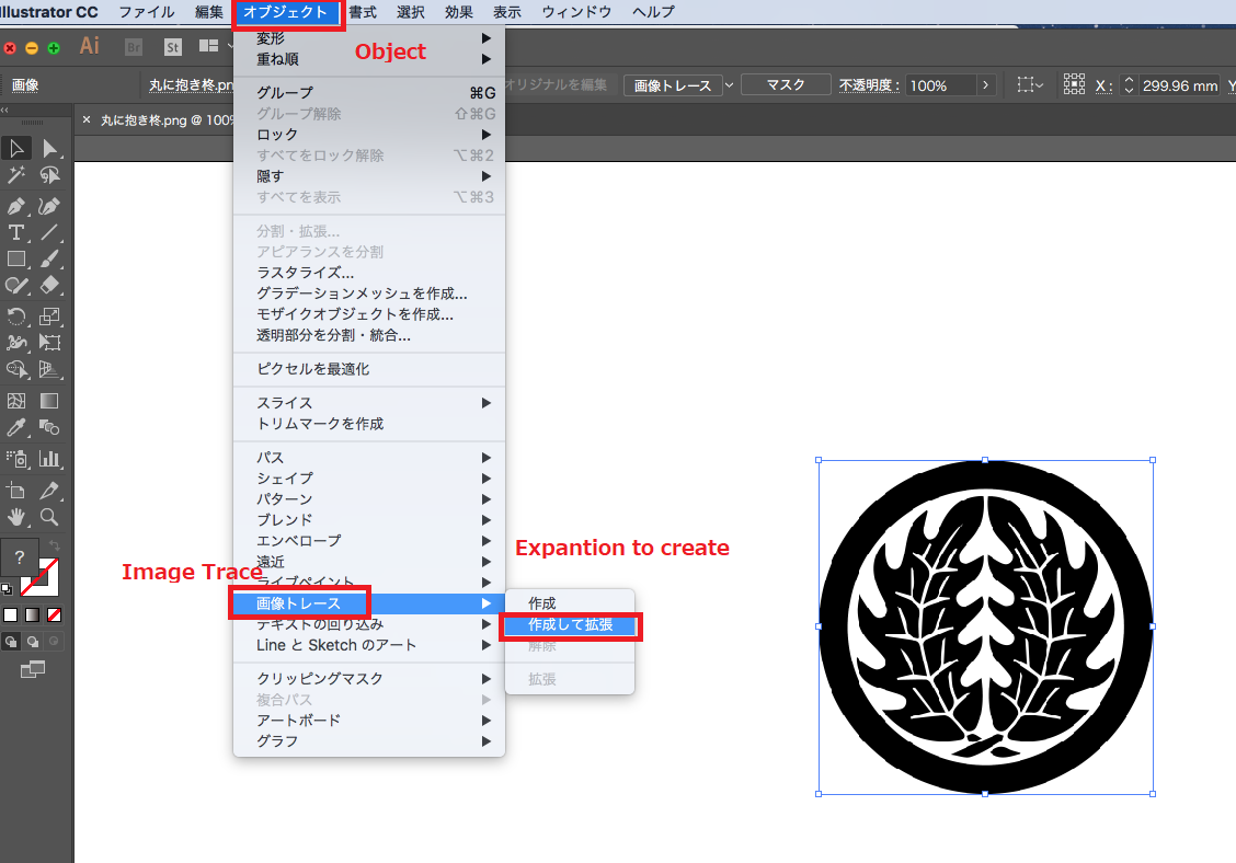
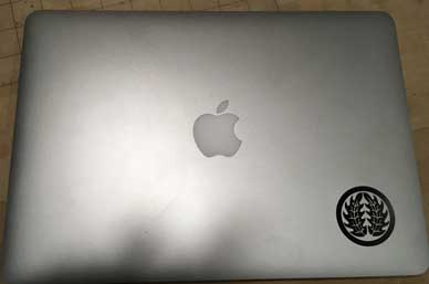
I decide to make sticker of my family crest.Family crest is a crest transmitted from its ancestry to its family.To put it easy, it is like a logo of that family. Family crest is printed to Japnanese taraditional formal wear and engraved to tomb.
My family crest is called "Maru-Ni-Daki-Hiiragi" with motif of a holly tree as follow.
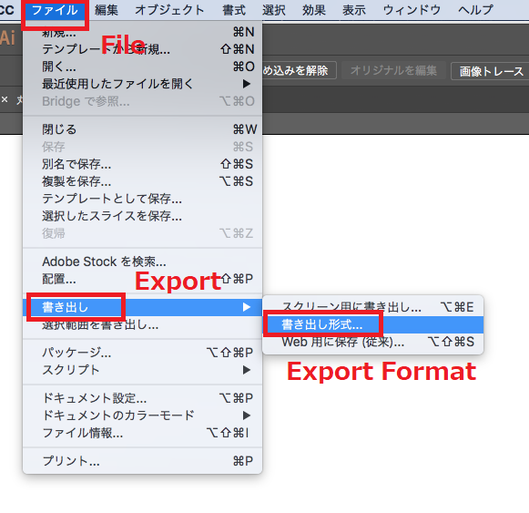
Trace with Illustrator
import png file & trace data
exprort to DXF file
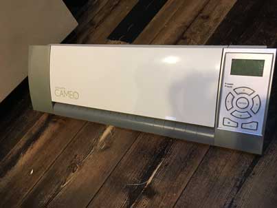
Vinylcutter
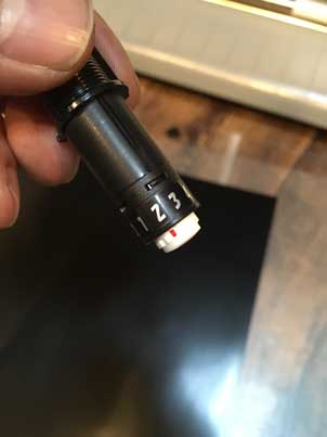
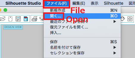
Our vinylcutter is CAMEO.Control software is Silhouette Studio
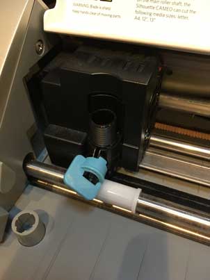
Set the cutter length & set cutter to CAMEO
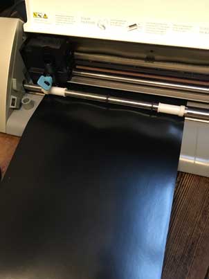
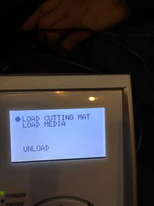
Set sheet & load media
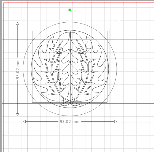
Open DXF file
Change size
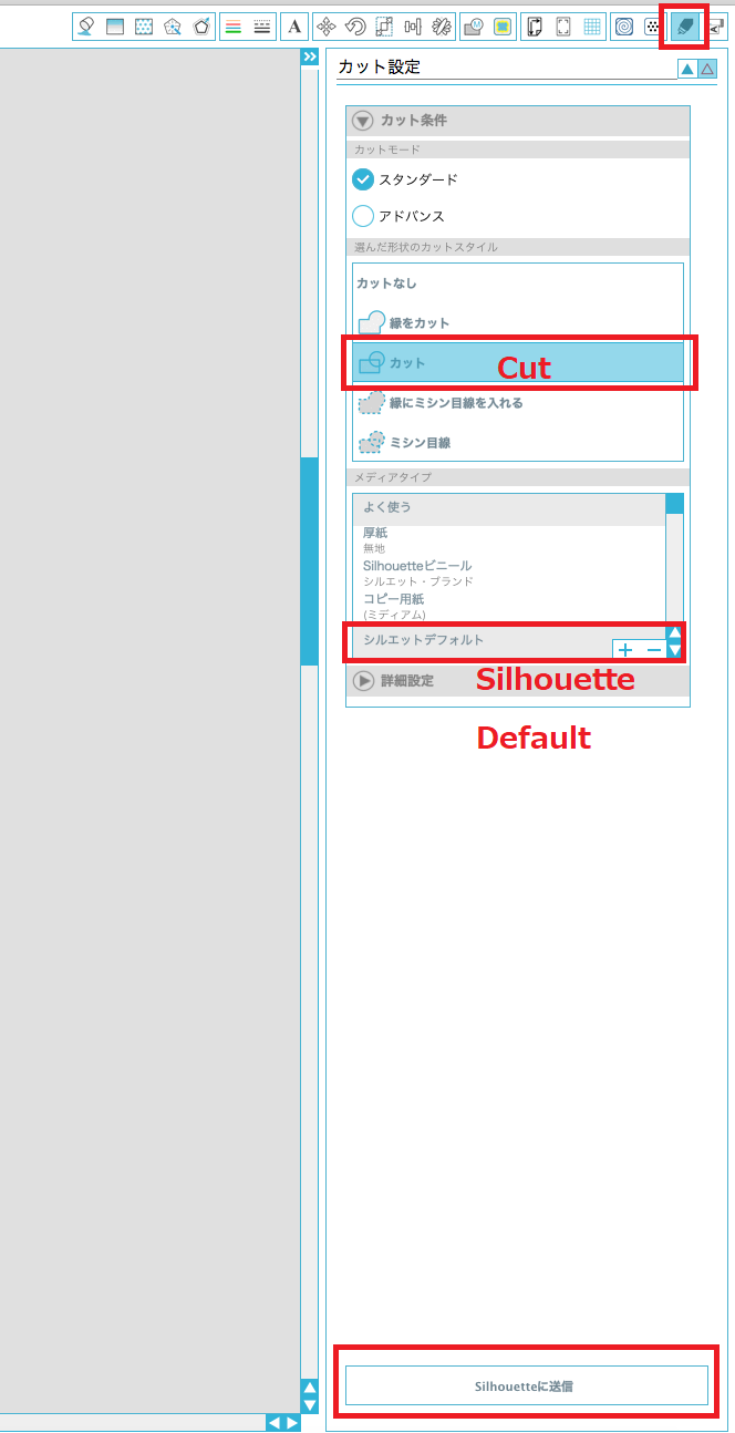
Cut
Macbook pro with family crest