This week assignment is to read a microcontroller data sheet, program the board to do something. Compare the performance
and development work flows for other architectures.
Microcontroller Data Sheet
For the moment there are two relevant data sheets, ATtiny 44
and ATtiny 45. I have going through some of chapter in the ATtiny 44 data sheet.
Eagle and the Hello-44 Board
As in week 7 I use Eagle to redraw the Hello-44 board. I change the board to contain a led and a button. Based on an idea from FabLab in Oulu,
in addition to the button I put in a low pass filter, to kill peak voltages coming from any button operation.
I use the Eagle 8.6.3 premium.
To install the MIT fablab library, click on http://academy.cba.mit.edu/classes/electronics_design/index.html,
circuits fba.lbr.). Right click on the fba.lbr and save link as, save it to he Eagle folder (I use c:/EAGLE 8.6.3/lbr/.
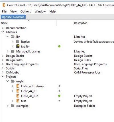
Now we set up the libraries. Please turn all the libraries off (On the main folder right click and select "Use none".
Turn the fab.lbr on (select Use), and in the main (Managed Libraries) turn on the "supply1.lbr" and the "rcl.lbr" libraries (See Figure 1).
Figure 1. Libraries management.
I start to create a project (File->New->Project). The projects are stored locally, C:/Users/jdu/Documents/eagle/.
Schematic
Now we are ready to begin the schematic creation.
Select File -> New -> Project, which creates a new empty project.
Right click on the created project and select New -> Schematic. This opens the schematic view.
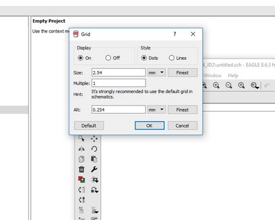
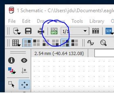
In the schematic you can change the imperial units to standard units from, View -> Grid.
In there you can select mm and show the grid to make view a little bit more clear (See Figure 2).
Clue: Set Display on and Stylt to Dots.
Figure 2. Grid setting in Eagle.
The components are placed on shchematic by choosing Edit -> Add or by choosing Add from the side panel.
Selecting that gives you a list of components which you can choose for your schematics.
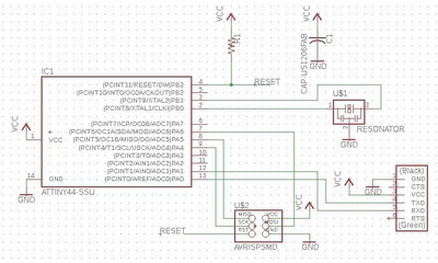
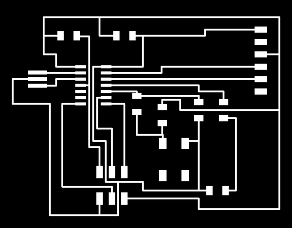
Before we do that we will open the hello-board from the Fabacademy and make the same layout in EAGLE as Neal make the board.
Go to http://fab.academany.org/2018/schedule.html and select "electronics design"
go to assignment and select redraw the echo hello-world board.
Click on the board
Some explanation of the board picture. Green letters indicate what types of device.
Note that XTAL1 stands for crystal but we will use a resonator (the two capacitors are included)
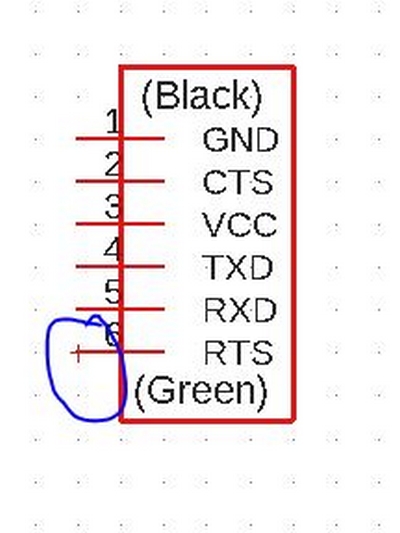
IC1 is integrated circuits. R1 is a resistor, C1 is a capacitor, J1 is the ISP pin header, and J2 is a jumper (from one board to an other board).
The FTDI-cable support the board with power (VCC) and communicate with the computer (Tx and Rx).
Now we can select components from the libraries based on planned component list, double click on the component and
place in on the schematic. If you want to delete a component from the schematic,
mark it with the mouse and push on the delete button.
From the library we will select:
fab library:
ATTINY44-SSU = IC1 t44
RESONATOR = XTAL1
RES-US1206FAB = R1 (FAB gives larger space between the legs
CAP-US1206FAB = C1
AVRISPSMD = j1 ISP
FTDI-SMD-HEADER = j2 FTDE
supply library:
VCC = V
GND = GND
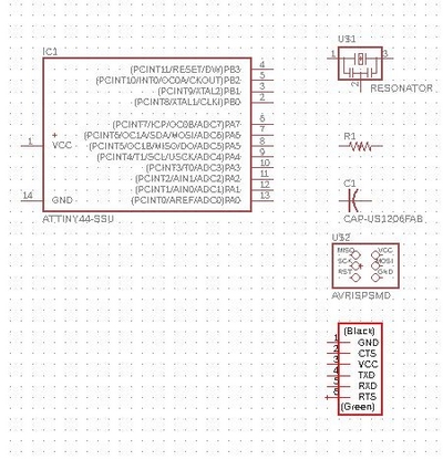
Now the schematic could lock like as shown in Figure 3 (Without VCC and GND)..
Figure 4. How to select a component in the EAGLE schematic.
To move a component on the schematic you need to select and hold the red cross on the component image(see Figure 4).
Figure 4. How to select a component in the EAGLE schematic.
Now you can move the component into a proper position.
From the side menu select line or Net to connect the components. Please follow the line from the board created by Neal.
Place labels: Alternative for line drawing from component to component. Draw a half line out from a component
and put a label on it (give it a unique name). Do the same with the other component you want to connect. Define the name of the line/label.
For the Hello board we will put label on RESET.
Note if you want to connect two lines you have to use a junction.
Hint: VCC points up, GND points down.
The resonator connection is: 1 to XTAL1, 2 to GNS, and 3 to XTAL2 on the ATTINY44.
Connection all the component you board could look like the board on Figure 5.
Figure 5. Hello-44 board.
Save your work.
Make the Board
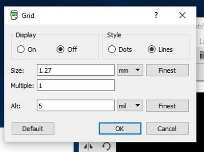
To create a board select "Generate/switch to board" (See Figure 6), and select "Create from schematic".
Figure 6. Switch to board.
Now you have to place the schematic inside the board line.
Hint: IC1 pin 1 upper left corner. Note that pin 1 is not all ways VCC.
Hint: ISP pin 1 upper right corner.
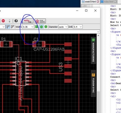
Now to re-arrange the line select "Route". Please change the setting of the lines (See Figure 6 and Figure 7).
Select the grid line to 50 mil (1.27 mm) and then select the width to 0.36.
Figure 7. Setting the route unit. Figure 8. Setting the route size.
Connect the Route from the middle of the pads. To delete the Route select Ripup from the side menu. Note you can use the Autorouter
Design Rules Settings
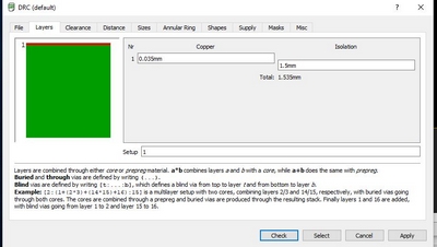
Select from the side meny (at the bottom) DRC (Design rule check)
Layers (Figure 9)
Setup: 1. Remove 16, because we only have cupper layer on the top.
Clearance
Least clearance is the size of the milling bit, 1/64" bit = 0.4 mm.
Wire = 0.45mm. Copy this to all other Different Signals.
Don't change Same Signals.
Size
Minimum Width = 0.3mm.
Minimum Drill =0.9mm (from 1/32=0.8mm)
Distance
Copper/Dimension = 1mil
Figure 9. Design rules settings: Layers.
Hint: To be more precise with the draving change the setting in the grind set alt to 5, and use the alt = ALT button on the key board.
Hint:You can tweed the line a bit using the eye from the meny and change the line coordinates.
Hint: To continue a Route press alt on the key-board.
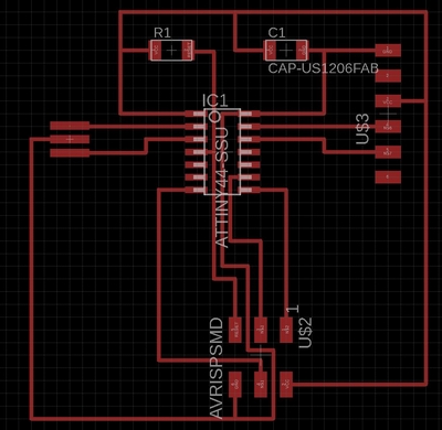
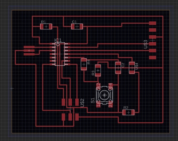
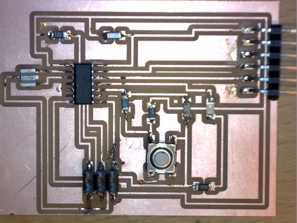
Figure 10 shows the final Hello-44 board. Now we have to put some extra components on it.
Figure 10. My re-drawing af Neal Hello-44 board.
Extra Components
I want to put a led (with a resistor)to the IC1 and a bottom. Based on the idea from Oulu I want to put the button inside a low pas filter to compress any peak signal that will be connected to the operation of the button.
From the library we will select:
fab library:
RES-US1206FAB = R2, R3, and R4
CAP-US1206FAB = C2
6MM_SWITCH6MM_SWITCH = button S1
LEDFAB1206 = led
supply library:
VCC = V
GND = GND
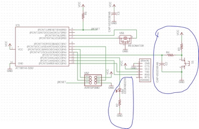
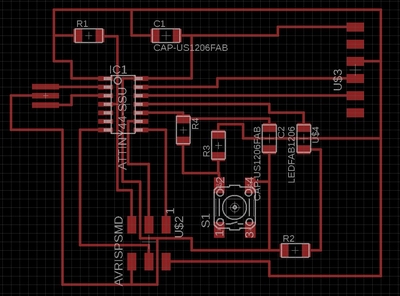
Figure 11 shows how I connects the added components, and Figure 12 shows my version to the final board.
Figure 11. The schemantic of the Hello-44 board with added components. Figure 12. My final Hello-44 board with added components.
The values of the components is:
R1 = 10 kOhm
R2 = 499 Ohm
R3 = 49.9 kOhm
R4 = 49.9 kOhm
C1 = 1 myF
C2 = 10 nF = 10000 pF
Led = red
Production
Fit the boarder line to the circuits board.
How to find the size of the board: Right click on one of the side of the surrounding rectangle and you will see the x and y coordinates in the selected unit.
Layers:
On the side menu, click on "Layers setings..."
Top is copper. t = top, b = bottom. On the bottom there are bmp images layers (e.g. 200)
Select None, Select Top, Pads, and Vias.
Select File->Export->Image. Select Monochrome, set the Resolution high 1500 dpi and save the picture "hello_44_jd2_traces" png (See Figure 13)
Figure 13. My Hello-44 traces image.
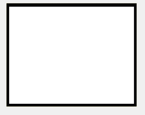
Now we need to add the outline to the board.
Add a rectangle outside the board to layer 200bmp (See Figure 14)
Figure 14. For the trace with outline, add a rectangle around the board.
Turn off the dimension layer and the bmp layer (200 bmp), and export the file as a picture (hello_44_jd2_traces_with_outline. This picture will be a bit larger then the former picture.
Turn of all the layer and put on the dimension layer, and export this third image as e.g hello_44_jd2_outline.
Now we will take this picture into GIMP, and edit the hello_44_jd2_outline file.
In GIMP flood fill the middle area with with color (See Figure 15). Save the file using: File->Overwrite .....png. Close GIMP.
Figure 15. The result of the outline file in GIMP.
Now we can go to mods to cut the board (Follow the link please)
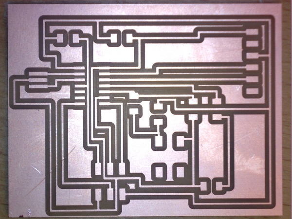
Soldering Result
Figures 16 and 17 show the milling and the soldering result. I think that the milling is OK.
The soldering could be better, unfortunately I burn two traces, I repaired them using copper wire.
Figure 16. Left: The result of the milling. Right: The final Hello-44-JD2 board.
Start Programming the Hello-44 Board
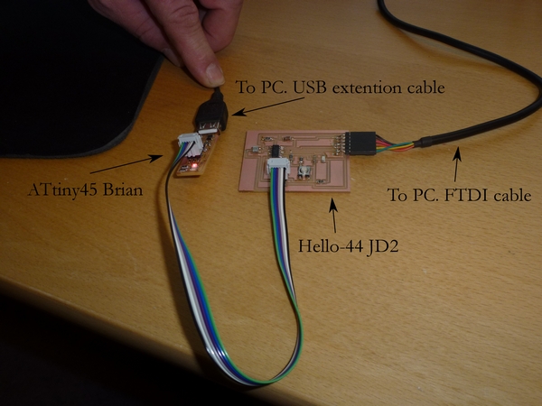
1. Connect the programmer (USBtinyISP or IPS44 board) to the computer using a USB extension cable.
2. In Git Bash write: "avrdude -c usbtiny -p t45". if The answered is : "averdude.exe: initialization failed, rc=-1 ......" then there is a connection from the computer to the FabISP board.
NOTE: I tried the USB port in the dock-station, but I did not get any connection, even though the USBtinySPI shows up under "Bluetooth & other devices" in Windows.
3. Connect the programmer to the Hello-44 board with an ISP cable, make sure that the ground pins are connected to each other.
4. Connect the Hello-44 board with the computer using an USB/FTDI (6 pins 5 Volt)cable. Now a red ligth should turn on on the programmer board. (See Figure 17)
Figure 17. The connection for programming the Hello-44-JD2 board.
5. From http://academy.cba.mit.edu/classes/embedded_programming/ download the code hello.ftdi.44.echo.c
and the make file hello.ftdi.44.echo.c.make , to a local programmer folder.
6. In Git Bash change directory to the local programmer folder. (in my case "cd C:/temp/FabLab/Fabacademy/hello_44_JD2/program")
Now you can follow this recipe, or continue with point 6 below. NOTE in the recipe do not use the sudo command in Git Bash.
Observe that the green led flashes during the following executions.
7. Execute: "make -f hello.ftdi.44.echo.c.make". This will make a hex file for flashing.
8. Execute: "make -f hello.ftdi.44.echo.c.make program-usbtiny-fuses". This will set the fuses.
9. Execute: "make -f hello.ftdi.44.echo.c.make program-usbtiny". This will make the hello world.
Now we will check the connection to the Hello-44-JD2 board.
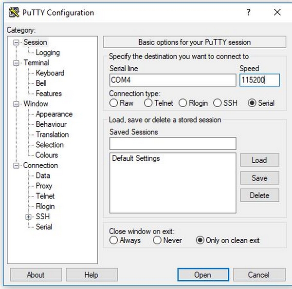
To find out what com port the FDTI is connected to use (Right click on the Windows start icon, select Control Panel -> Device Manager -> Ports. My Device manager shows USB Serial Port (COM4) is used by Manufacturer: FTDI.
Open the program "PuTTy". The settings are: Connection type = Serial, Serial line = COM4 (is for this board), and Speed = 115200 (See Figure 18).
Figure 18. The PuTTy settings for the test of the connection with the Hello-44-JD2 board.
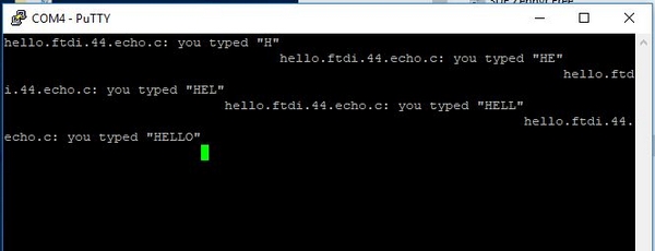
Open the PuTTy with the settings, and start writing (e.g. HELLO). Figure 19 shows the answers.
Figure 19. The PuTTy settings for the test of the connection with the Hello-44-JD2 board.
Now we are ready to continue to program the extra component I put on my Hello-44 board.
But first something about the ATtiny 44 datasheet.
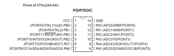
I'l start with an image of the ATtiny pins (See Figure 20).
Figure 20. Pinout of ATtiny 44A.
In my summary, I have looked through the summary of Heidi Hartikainen from Oulu. I have the Atmel studio installed,
and I would like to use it to create a c program similar to what Heidi did,
but I do not that familiar with the c programming yet to be able to follow Heidi. So at first I use the Arduino IDE (See later).
Ports
The ATtiny 44 has 2 ports (Port A and Port B).
Port A/B is a 8/4-bit bi-directional I/O port with internal pull-up resistors.
The Port A/B output buffers have symmetrical drive characteristics with both high sink and source capability, except PB3 which has the RESET capability.
As inputs, Port A/B pins that are externally pulled low will source current if the pull-up resistors are activated.
The Port A/B pins are tri-stated when a reset condition becomes active, even if the clock is not running.
Port A has alternate functions as analog inputs for the ADC, analog comparator, timer/counter, SPI and pin change interrupt.
Configuring the pins
Each port pin consists of three register bits: DDxn, PORTxn, and PINxn. The DDxn bits are accessed at the DDRx I/O address, the PORTxn bits at the PORTx I/O address, and the PINxn bits at the PINx I/O address. The DDxn bit in the DDRx Register selects the direction of this pin.(attiny datasheet, (pp. 53-->))
-If DDxn is written logic one, Pxn is configured as an output pin.
-If DDxn is written logic zero, Pxn is configured as an input pin.
If PORTxn is written logic one when the pin is configured as an input pin, the pull-up resistor is activated.
To switch the pull-up resistor off, PORTxn has to be written logic zero or the pin has to be configured as an output pin.
The port pins are tri-stated when reset condition becomes active, even if no clocks are running.
If PORTxn is written logic one when the pin is configured as an output pin, the port pin is driven high (one).
If PORTxn is written logic zero when the pin is configured as an output pin, the port pin is driven low (zero)."
Chapter 10 gives some programming examples of how to configure the pins.
Final Programming the Hello-44 Board
I'l use the Arduino IDE to create a c-code to my Hello-44-JD2 board.
For installing the USBtinyISP please follow this link.
WARNING: FTDI-HEADER BRAKES EASILY!! The result! Start milling and solderint the third Hello-44 board.
Back on the track. After some re-soldering the Hello board answered HELLO to me (so fare so good).
Arduino IDE settings and Programming the Hello Board
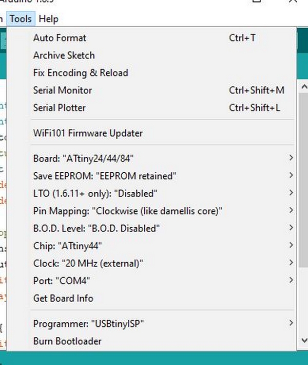
Open the Ardoino software. Set the tools as shown in Figure 21.
Figure 21. Arduino settings for the USBtinyISP board.
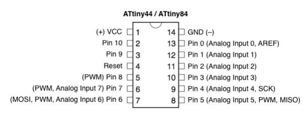
In Arduino the pins numbers are redefined (see Figure 22) check it before starting the c-programming in Arduino.
Figure 22. Arduino pinout for the ATtiny 44.
I program my board so the led will start flashing while the bottom is pushed down, otherwise the led is just turn on.
Here is the Arduino program:
const int ledPin = 2;
const int buttonPin = 3;
int buttonstate = 0;
THE PROGRAM WORKS, jubii.
I tried both programmers (the 44 and the 45), and my Hello-44-JD2 board do as told.
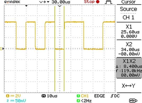
The Oscilloscope
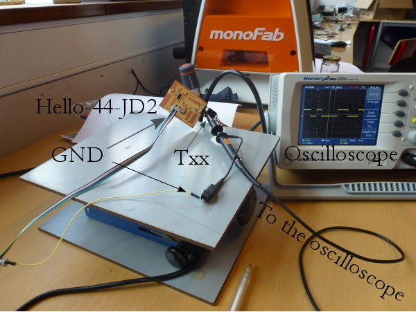
I connect the Oscilloscope ground through the ISP heater ground pin, and I probe the TXX on the FTDI (See Figure 23).
Figure 23. The set up connection for probing the Hello-44-JD2 board using an oscilloscope.
The digital oscilloscopes have a lot more functions than the old analog oscilloscopes.
To catch up a window of a sequence of short digital pulses use the single mode on the oscilloscope. A good start window is 5 Volt vertical and 25 mys horizontal.
Figure 24 shows the sequence of pushing the character: "5". The "unit" pulse has a length of approximately 8.8 mys. HIGH = 4.8 Volt and LOW = -80 mV so the pulse hight is 5 V.
The binary sequence on Figure 24 is 010101100. If the first bit is a starting or control bit, we have the rest of the code gives the number:
1*1+0*2+1*4+0*8+1*16+1*32+0*64+0*128 = 53.
This is the ASCII code for the character "5". Link to ascii code.
Figure 24. Hard copy from the oscilloscope screen, the pulse sequence from the Hello-44-JD2 board of number "5". The sequence is 010101100 this is the binary code for the decimal number 53 which is the ASCII number for the character "5".