This week assignment is to test run out, alignment, speeds, feeds, and tool paths for the machine, and make something big
The Shopbot was installed recently, so I have approached this tool very gently :).
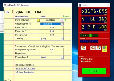
I started to use the VCarve software and cut something out (See Figure 1).
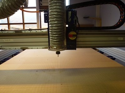
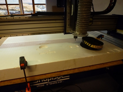
In all my following jobs I always begin with air cutting.
At the very beginning I also use styrofoam (See Figure 1).
For the air cutting I chose the 3D Offset Proportion 1,1,1 and I Put the z-axis so height that by no chance it will reached the material.
By coincident I manage to "cut" with out turning the spindle on; lucky me I was using the styrofoam as cutting material.
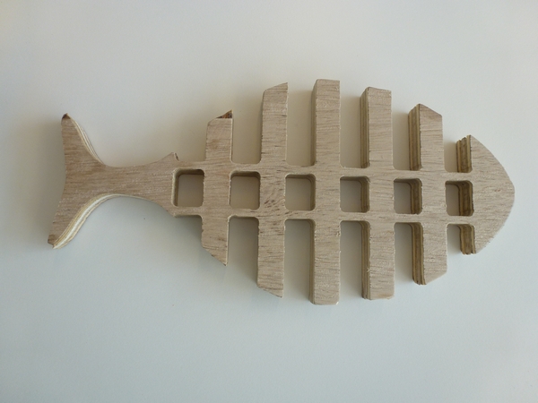
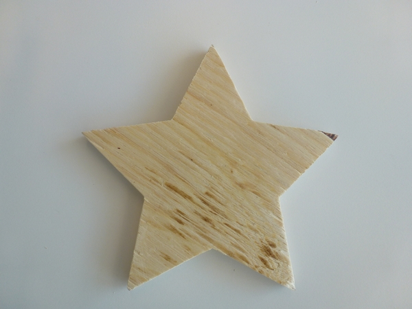
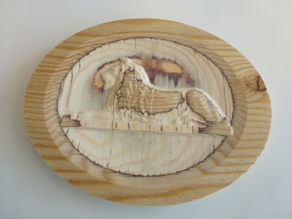
Figure 2 shows the very first cutting examples I did.
Figure 1. My first procedures cutting using the Shopbot. Air cutting (left and middle) and styrofoam cutting (right). Figure 2. My first examples of wood cutting using the Shopbot.
Pocked - Dimension Test
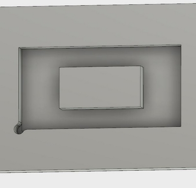
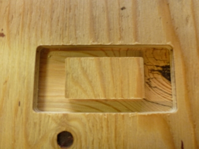
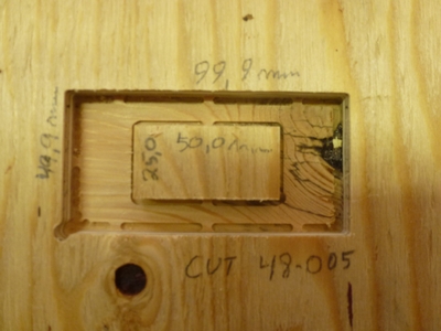
Figure 3. A pocked in playwood birc. Left: Pocked model in Autodesk Fusion 360.
Middle: Cut using 1/4" One flute straight (Onsrud 48-005).
Right: Finish, using 1/8" Two flute up-cut (Onsrud 52-240)
To test the horizontal precision I cut out a pocked (x,y,z) = 50 x 100 x 10 mm in play wood and left a
squared area (25 x 50 mm) in the middle of the pocked (See Figure 3).
The modeled the pocked I use the Autodesk Fusion 360 Model and Cam.
For the cutting I first use a Ø1/4" flat tool for "Adaptive clearing" followed by a
Two flute up-cut doing 2D Contour for the pocked wall and a Dog-bone.
I created this first Dog-bone geometry my self (based on https://www.youtube.com/watch?v=w5Xa7oTPcYM),
but later I used a Dog-bone Add-ins (See later).
Based on inspection of the result I conclude that on the (outer) inside wall of the pocked
the horizontal precision was -0.1 mm compares to the model.
On the outside of the inner wall the cutting precision was 0.0 mm compares with the model.
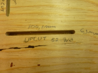
Line - Clean Cut Test
To study how clean a cut could be and to reveal the difference between down- and up-cut at the material surface
I use VCarve to model a cut of two 100 mm lines through 12 mm play wood.
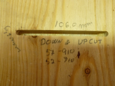
Figure 4 shows the result of the cuttings. The lines becomes approximately 2 tool radii (1/4" = 6,3 mm) too long.
The claim was that if we start to cut with a down-cut tool, the result would be cleaner compare with a up-cut tool.
I could not observe any significant difference between those two cutting methods. (See Figure 4, left and middle).
Figure 4. Clean cut test. Left: A line cut using 1/4" two flute up-cut Onsrud 52-910).
Middle: A combined line cut starting with a down-cut (Onsrud 57-910) followed by the up-cut (52-240).
Right: Up-cut, view from the bottom of the material.
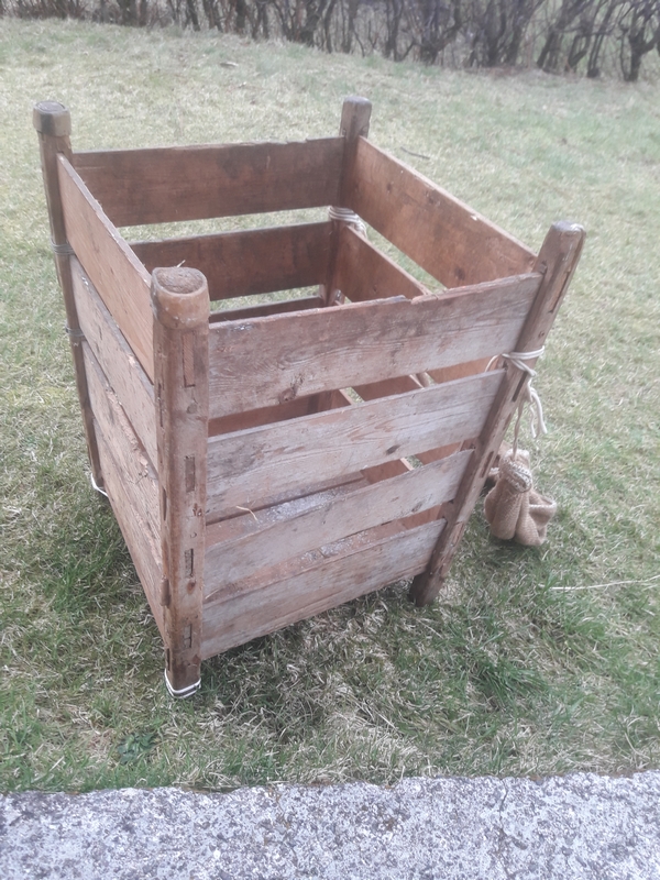
Something Big
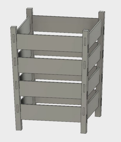
To make something big I planned to do a wooden creel. The model is based on a old creel that my grand father used before the World War II.
My focus will be on the joints.
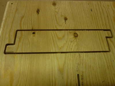
Figure 5. Left: An old wooden creel. Middle: The supports are reinforced with horn. Right: Sheep with horns.Figure 6. Left: Fusion model. Right: The first cut of one of the side boards.
As I worked for a few days drawing the creel, I had to recapitulate. There was too many crooked angles.
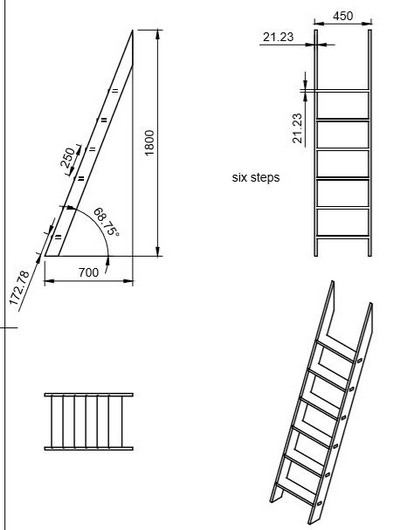
So the recapitulation results in a ladder.
I draw a model of a ladder with 6 stairs in the Fusion 360 Model module, using drawing parameters.
I installed a dog bones Add-ins (See https://www.youtube.com/watch?v=EM13Dz4Mqnc).
To lay all to bodies (component) flat for cutting, I installed and run NESTER (See https://www.youtube.com/watch?v=7SY367qt3YQ).
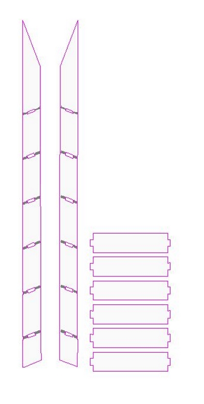
Before the final cutting, I export a STL file of the Fusion ladder model and import it to VCarve. Then I let VCarve to create a vector boundary around the components.
The VCarve digitalizing was bad, and the final result needs a lot of finishing touches by hands. I will not recommend this procedure.
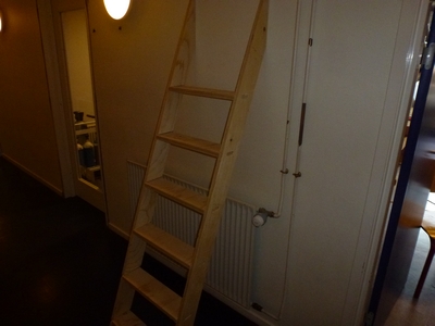
Figure 7 shows the model of the ladder, and Figure 8 shows the result.
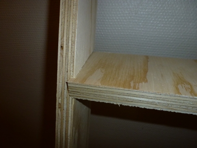
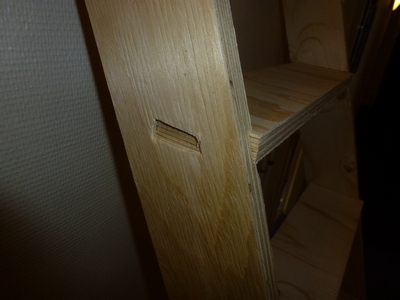
Figure 7. Left: Ladder. Drawing from the Fusion model. Right: Same model imported to VCarve.Figure 8. Left: The result, a ladder. Middle: One of the six stairs. Right: A joint.
Shopbot Settings
Based on the tools I have access to, I made a Excel spreadsheet for the Shopbot settings.
Below is the formulas and an example of the parameters I have tabulated.
Id: Onsrud 48-005
Comment: 1/4" Carbide Tipped One Flute Straight V Flute for Natural Woods, Composite Plastics and Woods, Foam
Diameter: 1/4", 0.25", 6,35 mm
CED: 1/4
CEL: 0.87
SHK: 1/4
OAL: 2.37
Chipload min: 0.005
Chipload max: 0.007
Flute: 1
Max Material thickness = CEL : 0.87", 22.1 mm
Cut depth = Diameter: 1/4", 0.25", 6,35 mm
Stepp over = Diameter/2 = 50%: 1/8", 0.125", 3.175 mm
Spindle speed [RPM] : 14000
Cutting rate = Chipload * Spindle speed * Flute number:
Min = 70.0"/min = 1778 mm/min.
Max = 98.0 "/min = 1.6 "/sec = 2489 mm/min.
Leed Feedrate = Max cutting rate * Lead coeff = 2489 * 0.1 mm/min = 249 mm/min
Ramp = Max cutting rate * Ramp coeff = 2489 * 0.1 mm/min = 249 mm/min
Plunge= Max cutting rate * Plunge coeff = 2489 * 1/3 mm/min = 830 mm/min = 0.5 "/sec
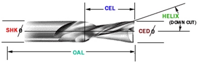
Figure 9. Tool definitions.
CED: CED is abbreviated for cutting edge diameter or the width of the cut the tool should make
through the work piece. CED has a tolerance in thousandths of an inch or .xxx decimal places.
CEL: CEL is abbreviated for cutting edge length and is the maximum thickness of the material it can cut.
CEL has a tolerance in hundredths of an inch or .xx decimal places.
SHK: SHK is abbreviated for shank diameter and is the nominal size of the shank which should match the collet size
of the spindle the tool will be used in.
SHK has tolerance in the ten-thousandths of an inch or .xxxx decimal places.
OAL: OAL is abbreviated for overall length and is the total nominal length of the tool from end to end.
OAL has a tolerance in hundredths of an inch or .xx decimal places.