This week assignment is to use the test equipment in my lab to observe the operation of a microcontroller circuit board, and to redo the echo-hello-world board and add some extra components.
Test Equipment
To test the connection on the circuit board I use an Ohm-meter with sound on. For signal testing I use an digital oscilloscope. The signals are very short, you need to play around with the oscilloscope settings. A good clue was to use the SINGLE mode.
Hello World Board
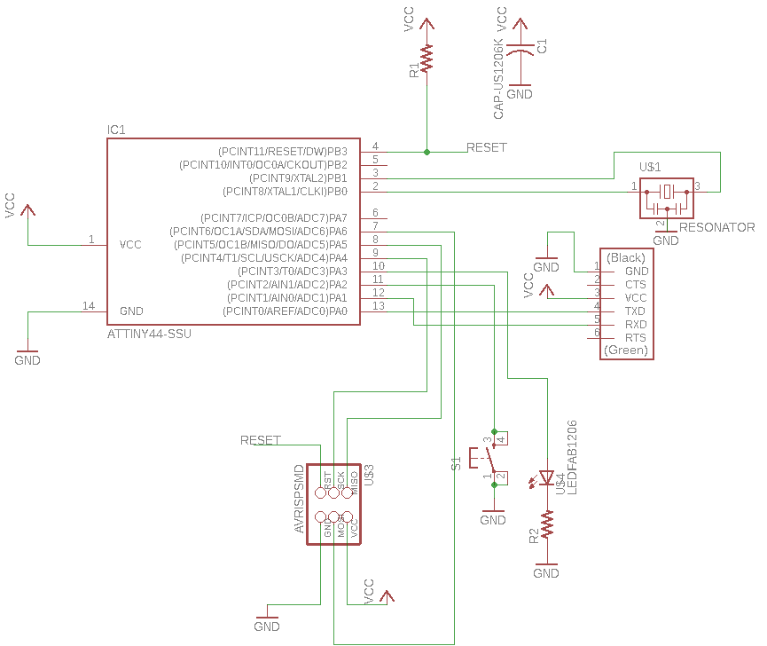
Based on the tutorial of Bas in Reykjavík I create the traces for the hello-world board I use the Eagle 8.6.3 premium version. Using Eagle I draw the schematic and processed the board (See Figure 1).
To the original board I add a button and a led with a resistor in serial. The size of the resistor is 499 Ohm, I did not make any calculations of this size.
The traces was export as a black and white png file. The outlines was re-paint in GIMP and then export as a b/w png file.
I use a SRM-20 Roland to mill out the PCB (See Mill a PCB using mods).
For the traces I use a 1/64" SE 2FL, and for the outline I use a 1/32" SE 2FL drill.
From Useful files (see link at the end of this page) you can open the board file and check the design rules.
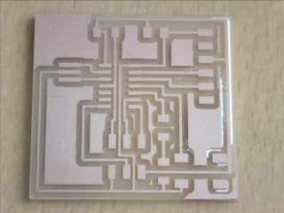
Figure 1. Using the Eagle software to draw the hello-world board. Left: Schematic. Right: Board design.Figure 2. Left: The hello board after the cut. Right: The result of the soldering. (Note the 6 pins headers are missing)
Unfortunately, I have no headings (2x3 pins or 1x6 pins) so I have to wait to program the board.
BREAK and continue.
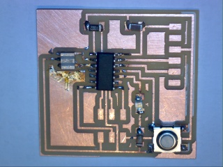
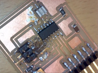
I have finished the board (See Figure 3).
Figure 3. The final(almost) hello board.
I use the ISP 44 and Ubunto. to set the board, but for the final programming I use the Arduino software.
I run the Echo test using python term.py and in addition I used the PuTTy program in Windows, both programs work with success.
I add a led and a button. I was able to program the light as I but the button shows unstable voltage. The header was a bit lose, so I decided to make a re-soldering, and that was the end of that board.
The Arduino code:
const int ledPin=3;
int timediff =100;
void setup() {
pinMode(ledPin, OUTPUT);
}