I use a SRM-20 Roland to mill out the PCB. For the traces I use a 1/64" SE 2FL, and for the outline I use a 1/32" SE 2FL drill.
To transfere the traces to the mille I use http://fabmodules.org/ and run the file using VPanel for SRM-20.
First I did the hello.ISP.44 board using an ATtiny44. The PCB copper plates were covered by some light resistance stuff, so you need to scrub the copper before the soldering
(See under assignment
http://academy.cba.mit.edu/classes/electronics_production/index.html.).
After soldering the ISP.44 board I started to work on the FabTinyISP board based on the Attiny45. Unfortunately, there were no more headings so I have to wait to program the ATiny45 (The programming is now finish, see below).
This week the drawings of the board are already done by fabacademy peoples.
Al the files with some relevance for the board production are included at the end of this page.
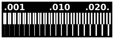
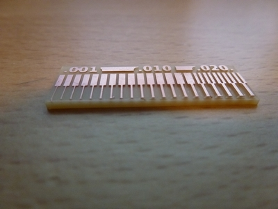
Linetest
I run a Linetest for the SRM-20 Roland using 1/64" SE 2FL. The test shows a good consistency with the "pins"
but the space was limited by the drill size 1/64" (0.4 mm)(See Figure 1 and Figure 2).
Figure 1. Planned line test.Figure 2. Results of the linetest.
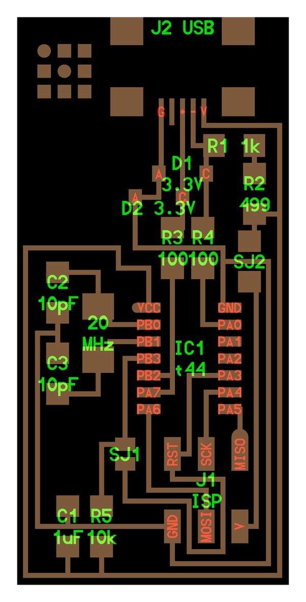
The ISP 44 Board
Figure 3 shows the sketch of Neil's ISP board.
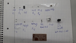
Figure 3. Sketch of the hello.ISP.44 board.Figure 4. Preparing for the soldering of the hello.ISP.44 board.Figure 5. Upper: The second attempt to cut, soldered, and programmed the ISP 44. Under: The First attempt, did not succeeded.
Figure 4 shows the components that is needed for the ISP 44 board stick to a paper, here is a list of the components:
Resistor R1 = 1 kOhm
Resistor R2 = 499 Ohm
Resistor R3, R4 = 100 Ohm
Resistor R5 = 10 kOhm
Capacitor C1 = 1 myF
Capacitor C2, C3 = 10 pF
Zener Diode D1, D2 = 3.3 V
Jumper SJ1, SJ2 (R = 0 Ohm)
J2 Mini USB
J1 ISP 2x3 Header
IC1 ATtiny44
After the soldering of the ISP 44 board, I prepared to program the ISP 44. I spent some time to install a Linux version (Ubuntu) on my Windows desktop.
Unfortunately I could not get the first version of ISP 44 to work, it turned out that the micro controller turned wrong. When I tried to fix the problem,
everything went wrong. But in the second run, I got soldered and programmed ATtiny44. The program was tested and proved to work. For this I got help from Frosti
from Vestmannaeyjar and Jani and Jari from Oulu.
FabTinyISP Board - ATtiny45
I have cut out the FabTinyISP board (Brian version) using an ATtiny45 (Bas shows me an easy way to do this).
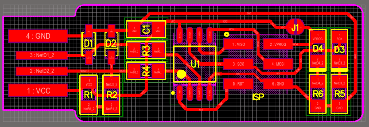
Figure 6. The FabTinyISP sketch.
I have not program this board because I am waiting for the header component (I got some component from Isafjordur, so now I back on the track).
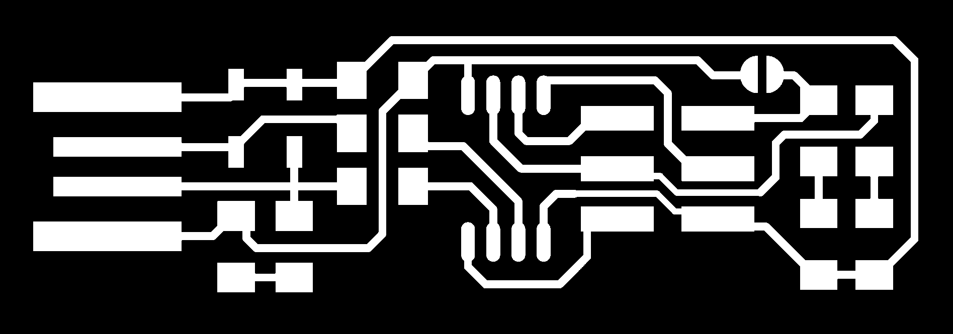
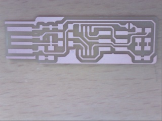
Figure 7. Left: The FabTinyISP board traces. Right: The board outline. Figure 8. The FabTinyISP board printing command to the SRM-20 cutter.
I use a SRM-20 Roland to mill out the PCB (See Mill a PCB using mods). For the traces I use a 1/64" SE 2FL, and for the outline I use a 1/32" SE 2FL drill.
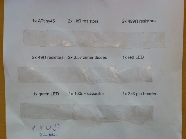
Figure 9. The FabTinyISP board list of components.
The components list for the FabTinyISP (ATtiny45):
1x ATiny45
2x Resistors 1 kOhm
2x Resistors 499 Ohm
2x Resistors 48 Ohm
1x red LED
1x green LED
1x Capacitor 100 nF
1x 2x3 pin header
1x Resistor 0 Ohm (jumper)
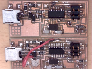
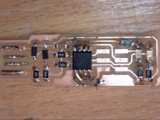
Figure 10. Left: The FabTinyISP board cut result. Right: After soldering (Note the 6 pin header is missing), but a red light is shining.
Recapitulation: I got to 6 pin header, but I could not program the board (using Ubuntu).
I solder a new board (See Figure 11) and program it with success.
Figure 11. The ATtiny45 Brian board. Upper: Nr.1. Lower: Nr. 2.
To solder the board, I followed the link "Building the FabTinyISP".
Using the Attiny44 board I programmed the ATtiny45 board nr. 2 using the Git Bash platform.
How to install all the Windows software (Git Bash,Atmel GNU Toolchain, GNU Make, avrdude and Zadig
please follow this link (
Installing the toolchain on Windows ).
The programming procedure: Using the GNU AVR toolchain on Windows 10
1. Download and unzip the firmware source code".
2. Open your terminal program and cd into the source code directory.
Run make. This will build the hex file that will get programmed onto the ATtiny45.
3. Edit the Makefile
4. Near the top of the file, find the line that says:
PROGRAMMER ?= usbtiny
and change usbtiny to whatever programmer you're using.
5. Run make flash.
6. Run the make fuses command. This will set up all of the fuses except the one that disables the reset pin.
7. run make rstdisbl [This will stop avrdude to talk to this chip again through the ISP header.
If everything is correct I now have a working ISP programmer.


