Group assignment: characterize your lasercutter, making test part(s) that vary cutting settings and dimensions.
Individual assignment: Cut something on the vinylcutter. Design, lasercut, and document a parametric press-fit construction kit,
accounting for the lasercutter kerf, which can be assembled in multiple ways
Vinal Cutting
This week I have supported students that need special education. The students wanted T-shirts with different motifs.
I thought this was a very good example to use for the vinyl cutting.
We have a Roland GS-24 CAMM-1 vinal cutter and a Secabo heat press for T Shirt press.
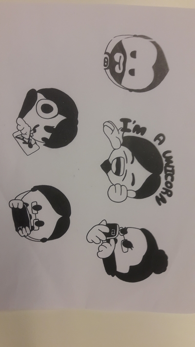
Step 1. One creative student draw one sketch of every student. (See Figure 1 Left.)
Step 2. A photo was taken of every sketch and transfered to Roland - CutStudio.
The digitized the photos in CutStudio we used "Image Outline" followed "Extract Contour Lines".
Note: For textile print you have to use the mirror function for the final results.
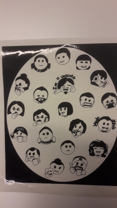
Step 3. The result was presenting to the students using cut Vinyl. (See Figure 1 Center.).
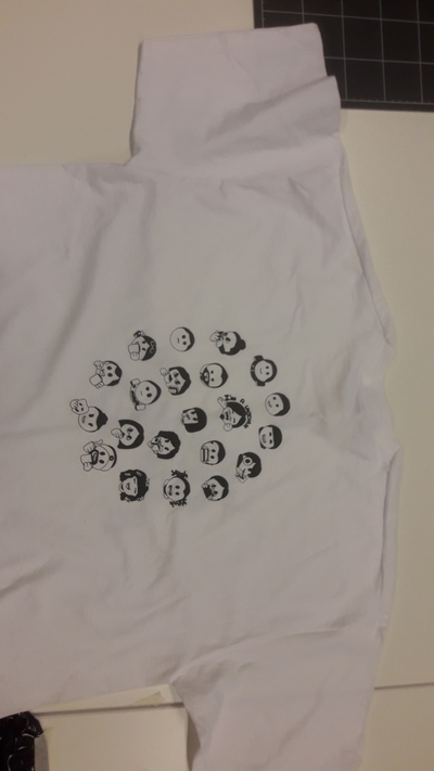
Step 4. The final result, using T-shirst vinyl and the heat press. (See Figure 1 Right.)
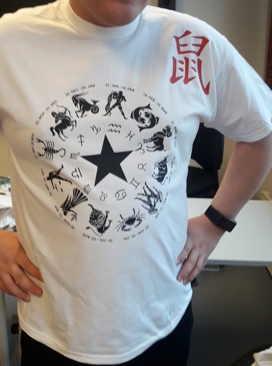
Final remark: Some students had special requests. (See Figure 2).
Figure 1. Left: Face sketch. Center: Raw result from Vinyl cut. Right: Result using T-shirt vinyl and heat press.Figure 2. Student with special interests.
Vinyl cutter my settings for textile vinyl:
Force 70 gf
PEN Force +1
Speed 5 cm/sec
Blade offset 0.25
Heat press procedure:
Set the temperature to 160 degC
Pre-press the T-shirt for 5 seconds
Press the textile vinyl on the T-shirt for 12 seconds
Post-press (using baking paper) for 6 seconds
Laser Cutting
I have do some characterization of the laser-cutter (Epilog-laser mini 40 W, 24x12 inches).
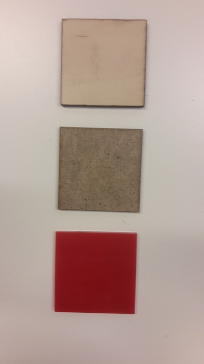
I tested the laser-cutter using a 5x5 cm square cut (See Figure 3).
The cutting method is described in wiki.fablab.is Figure 3. Left: Laser cut test of a 5x5 mm square of birc plywood (3.5 mm), massonit (2.8 mm), and colored plexy (3 mm).
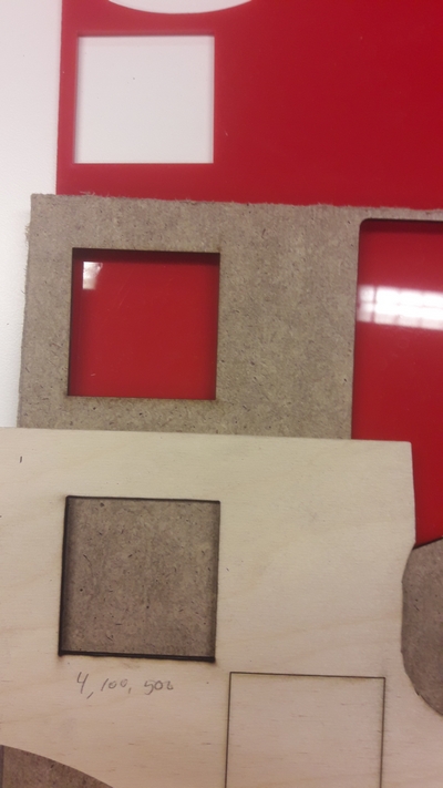
Right: The remains of the square cuttings.
The result for laser cutting a 5x5 mm square:
Conclusion: One notable conclusion is that for birc plywood the dimensions failure up to 0.6 mm for this settings of the laser cutter.
The group planned to do a test of how thick a Playwood Birc the laser could cut; but I have only access to 3.5 mm birc,
so as an alternative I tried to find a relation between the speed and the power to establish the border between the cut-through and the non-cut-through settings for 3.8 Playwood Birc.
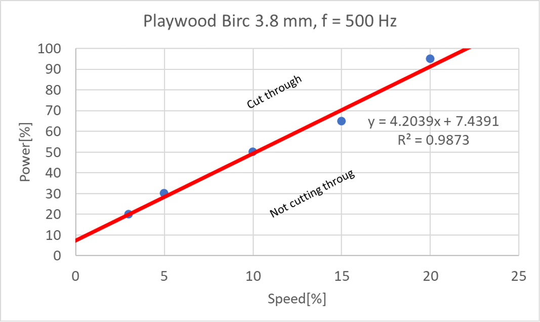
Based on a high number of square cutting bricks I found that the relation between the power (p) and the speed (s) for just cutting through the birc is: p = 4.2*s + 7.4. (See the plot below).
The cutting frequency was constant (500 Hz), the absolute power of the laser cutter is 40 Watt.
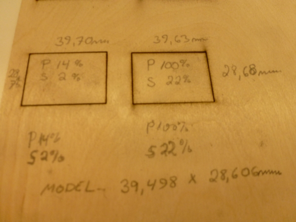
Figure 5. The experimental border between the cut-through and the non-cut-through settings for 3.8 Playwood Birc. Figure 6. The result of two cut-through cuttings, the settings is according to the p-s relation above.
To left: Power 14% and speed 2%. To right: Power 100% and speed 22%. Note lower power and speed result in a relative cleaner cut.
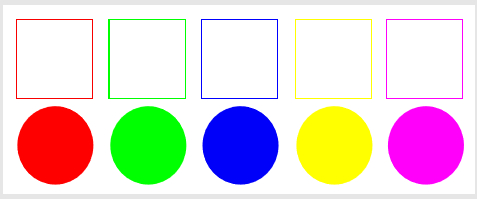
Laser Cutting Color Mapping
Figure 4. The input for the color mapping test.
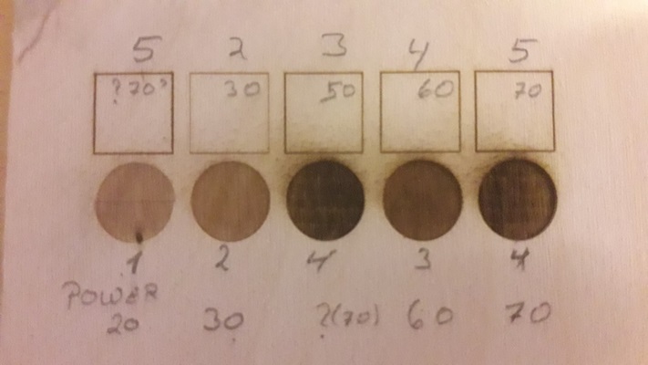
I test out how the color mapping works on the laser cutter. Figure 4 shows the original colors, and the numbers on Figure 5 shows the power as a function of the colors.
I was able to see the effect of the color mapping, but there was some problems to characterize the exact color from the screen.
So there was some inconsistence between the mapping and the result.
Figure 5. Laser cut color Mapping using different raster power. The raster speed held constant at 40%.
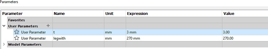
Parametric Drawing
Note in Week 3 I already tried a parametrization of my final project using Autodesk Fusion 360.
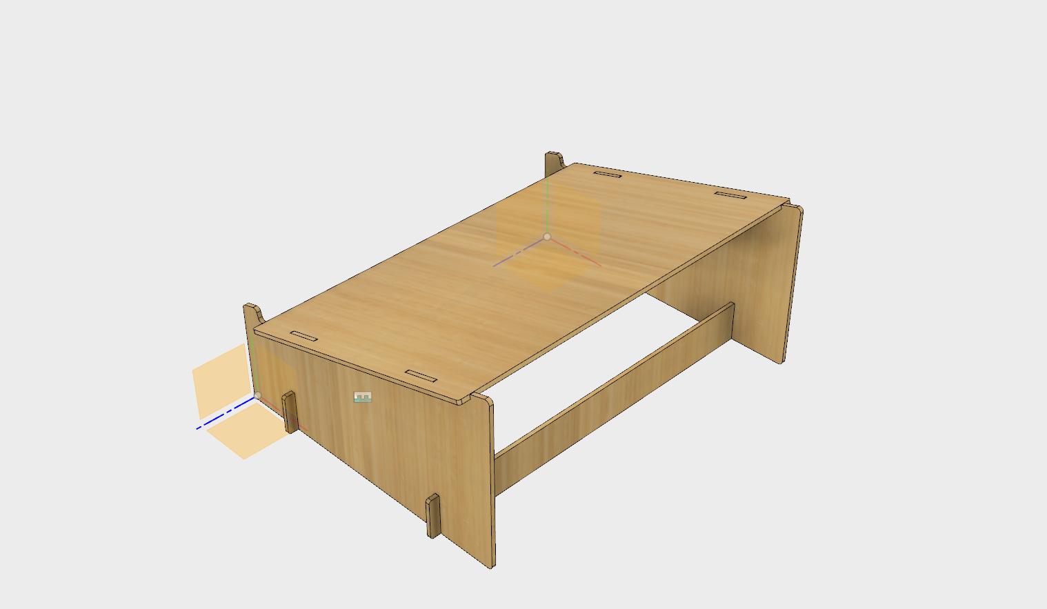
Last week, one of my short-legged colleagues wanted a foot stool. So this week I draw a footstool in Fusion 360, using parameters,
transfered the sketch to Inkscape and use the laser cutter to cut it out in massonit and birc plywood.
I got the idea from an example of Designing a Lasercut Laptop Stand.
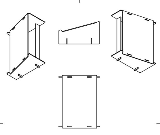
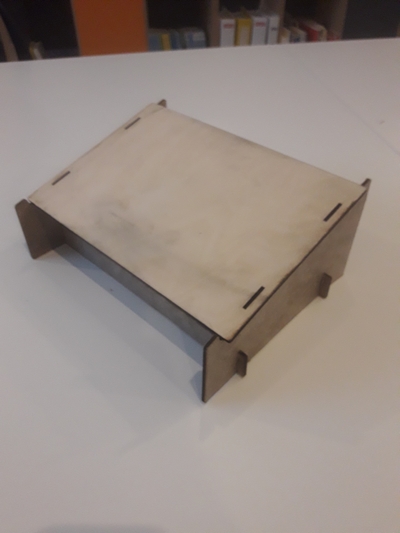
Figure 6 to Figure 9 show my Autodesk Fusion 360 model and the result from the birc plywood cutting.
Figure 6. Autodesk Fusion 360 sketch of a footstool.Figure 7. Projection sketch of the footstool.Figure 8. Autodesk Fusion 360 parametric sheet for the footstool.Figure 9. The resulting footstool.