This week group assignment is to Send a message between two projects.
This week individual assignment is to Design and build a wired &/or wireless network connecting at least two processors.
With lack of a group, I have put focus on the individual assignment.
Introduction
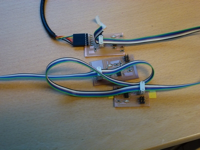
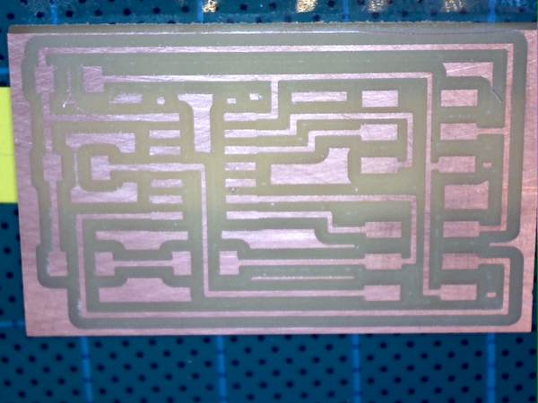
This week I have make three simple boards (the name or node_id is "0","1", and "2") for the networking based on a RS232 serial bus. I connect one of the board to
the COM4 port on the computer using a FTDI cable (See Figure 1). As microprocessor I choose the ATtiny44 over ATtiny45 as in Neil example,
that is because for my final project I think I will use the ATtiny44. So I have change Neil code for the ATtiny45 so the code
can be used for the ATtiny44.
For the serial connection I primary use the CoolTerm software. I also use PuTTY, but somehow I prefers CoolTerm.
Originally I programmed the ATtiny44 to flash a LED when a character was sent to the COM4 port, in addition if the board receive its name (number)
that specific board will flash again.
I order to control one of the boards (node_id 0) to interpret several commands, I make some experiments with the c-code for that board.
Inside the main c-code procedure I use the idea to record a sequence of characters. When a preselected sequence appears from the COM port e.g "1" "a" "b" "CR" board 0
will be flashing three times.
Figure 1. My RS232 network consists of three boards.
Individual Assignment
From the page http://academy.cba.mit.edu/classes/networking_communications/index.html under serial bus asynchronous
I look at the board file hello.bus.45.bridge board.
Note that Neil's board is for a ATtiny45.
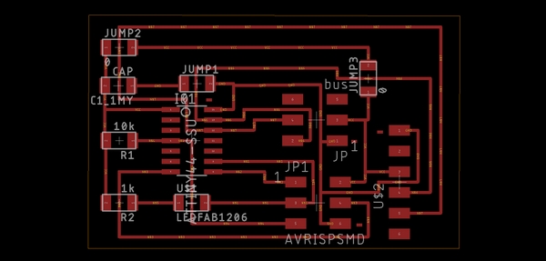
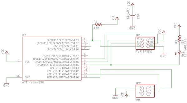
I redraw the bridge board (Board 0) using an ATtiny44 (See Figure 2). I did the same with the node board, but initially I had to use tow jumpers (Board 1, Figure 3);
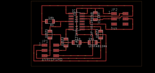
later I make a new node board redraw without the use of jumpers (Board 2, Figure 4).
Figure 2. Board 0 (The bridge board). Left: Eagle schedule. Right: Eagle board. Figure 3. Board 1 (The node board, with jumpers). Left: Eagle schedule. Right: Eagle board. Figure 4. Board 2 (The node board, no jumpers). Left: Eagle schedule. Right: Eagle board. Figure 5. Board 2 milled out.
Images of the Eagle boards was sent thorough the MOD's to a Roland SRM-20 for milling. For this procedure see the
week 9 exercise.
Figure 5 shows the result of milling the board 2.
At the end of this page, there is a list of usefully files, containing Eagle's files and parts.
Programming the boards
1. Start Git Bash and go to the week15 directory where the c and make files are.
Using the files for board 0 as and example.
2. In Git Bash write "make -f hello.bus0.44.c.make". This will make a hex file.
3. Connect the programmer (USBtinyISP or IPS44 board) to the computer using a USB extension cable.
4. Connect board 0 with the computer using an FTDI (6 pins 5 Volt)cable. Now a red light should turn on on the programmer board.
5. Connect board 0 and the USBtinyISP with an ISP cable.
6. Execute: "make -f hello.bus0.44.c.make program-usbtiny". This programs the board. The
7. For serial the communications: Open the program CoolTerm or PuTTy. The settings are:
Connection type = Serial, Serial line = COM4 (is for this board), and Speed = 9600.
To adapt the c-code to the ATtiny44 I need to modify the code.
The led pin is PA4, the serial pin in is PA0, and the serial pin out is PA1.
The modified define part of the c-code is:
For the board 0 the led setting is define in opposite direction as in Neil's bridge board (switch over clear and set for the LED)
I define the node_id as '0', '1' and '2' for the board 0, 1, 2 respectively.
I connect the boards with each other using the ISP cable. The FTDI cable was connected to board 0.
I run the program and the LED's responds perfect.
To test how I can use a sequence of characters to control the micro controller for one specific board.
I planned to use the board 0 as an example. The logic of the sequence of characters is:
"0" to select board 0, followed by "a", "b", and "CR". If board 0 receive this sequence the board 0 LED will flash several times.
The modified part of the c-code is:
static char by1; //Define by1-4 as static char.
....
by1=0; // reset by1, by2, by3,and by4 to 0.
....
get_char(&serial_pins, serial_pin_in, &chr);
by1=by2;
by2=by3;
by3=by4;
by4=chr;
if ((by1 == node_id) & (by2 == a) & (by3 == b) & (by4 == 13)){
led_delay();
flash();.....
}
For the serial connection i started CoolTerm. The serial port is COM4 and the speed is 9600 Baudrate,
8 data bits, none parity, 1 Stop Bits.
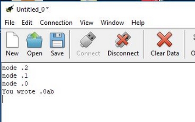
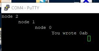
The tested sequence was:
"2","1","0","a","b", and "CR" (carriage return)
In addition to CoolTerm I tried PuTTY for the sequence of characters (See Figure 6)
Figure 6. The sequence of characters. Left: CoolTerm. Right: PuTTY.
Below is a video that shows the LED respond of the selected sequence of characters.
Video of the LED respond of this sequence of characters: "2","1","0","a","b", and "CR".