Measure the analog levels and digital signals in an input device.
Individual Assignment
Measure something: Add a sensor to a microcontroller board that you have designed and read it.
Introduction
This week I will connect an input device and read it. As an example I have use a light censor as an input device.
The board is based on the "light" board from Neal (See "light" on this page. See also Figure 1).
I did some changes to Neal's board. The ATtiny45 PB3 and PB4 pins I connect to a 2X3 header (See "INPUT DEVICES" on Figure 3). Now the input devices circuit is separated from the main board.
The board was drawn and solder as described in Week 9.
For this week assignment, I used a Redboard - breadboard to connect the light censor, the FTDI cable, and a voltmeter.
Below is a picture collage of the processes: Draw, cut, solder, and electrical circuit.
Figure 1. Neal's light board was used as basic.
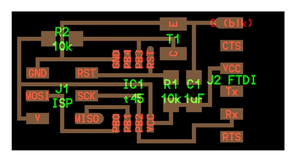
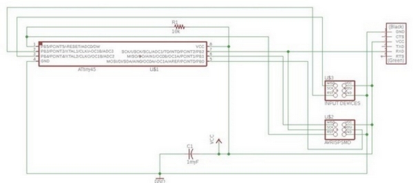
Figure 2. My EAGLE schematic of the light board.
The components list:
1x Attiny 45
1x AVRISPSMD = (j1 ISP)
1x FTDI-SMD-HEADER = j2 FTDE
1x CAP. 1myF
1x RES. 10k Ohm
1x (2X3) Header
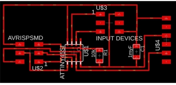
Figure 3. My EAGLE board of the light board.
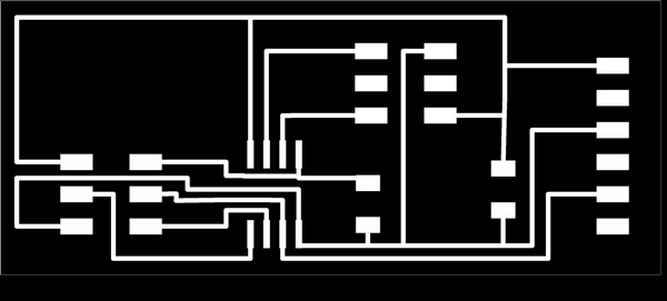
Figure 4. The board traces, to be milled using a Roland SRM-20.
Figure 5. The result of the soldering. Note! Because of lack of 2x3 pin headers, they have to be recycle.
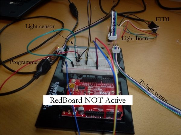
Figure 6. An overview of the setup. The breadboard was used, so different censors could be connected to the main board (pin PB3 and PB4).
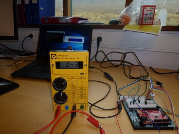
Figure 7. The figure shows the voltmeter (input voltage level). The python script is running on the computer (See the computer screen or Figure 8).
The FTDI cable could be connected directly to the board, but to be able to measure the voltage on the input I used a breadboard for this connection.
I also use the breadboard to connect the components that is missing on my board - compared with Neil's board, the components are a light censor and a 10 k Ohm resistor (See the sketch on Figure 8).
Figure 8. The board connection to the breadboard.
Programming
To produce the hex file: In Git Bash go to the project directory and write the command: make -f hello.light.45.make
I used avrdude (In Git Bash) with the resulting .hex file from Neal to flash the board with my programmer.
The command is: avrdude -p t45 -P usb -c usbtiny -U flash:w:hello.light.45.c.hex (See in "hello.light.45.make" for program-usbtiny)
For several days I tried to use the Arduino IDE for the serial communication, white out any success, so I give up using the Arduino IDE, and I aimed for Python.
I got good support from the homepage made by Jari UUsitalo.
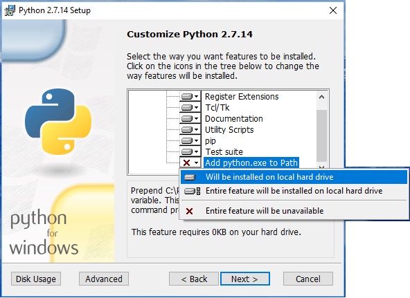
I installed Python 2.7.14 and changed the path setting:
Figure 9. Installing Python.
Then I downloaded Python Serial.
Unpacked the "pyserial-3.4.tar.gz" file: In Git Bash write "tar xvf pyserial-3.4.tar.gz".
or in the command prompt: "gzip -d pyserial-3.4.tar.gz" followed by "tar xvf pyserial-3.4.tar".
and install the serial, from the setup.py location: "python setup.py install".
In addition I download the NumPy package (I selected the file "numpy-1.14.3+mkl-cp27-cp27m-win32.whl"), and installed the package:
pip2.7 install numpy-1.13.3+mkl-cp27-cp27m-win32.whl
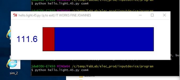
Now I work thorough Neil's hello.ligth.45 Python file and run the code in Git Bash: "python hello.light.45.py com4" (See figures 10 and 11).
The com port number I found from the computer Control Panel.
The Voltmeter and the number from the serial port increases if no light shined on the light censor (You probably can see this behavior on Figure 7).
Figure 10. High light observation.
Figure 11. Low light observation.
Summary
This week I have struggle with the problem to read the com port. I spent long time the use the Arduino IDE, with no success. Then I use Neil's Python script, and every things goes fine.
I did not have enough equipment to make Neil board, so I took some shortcuts using a breadboard for the final connection to the com port.
I think I got a good lesson to understand most of the steps in the process, but the are some lines in the Python script that I not fully understands. So fare so good.


