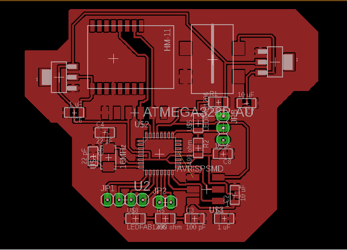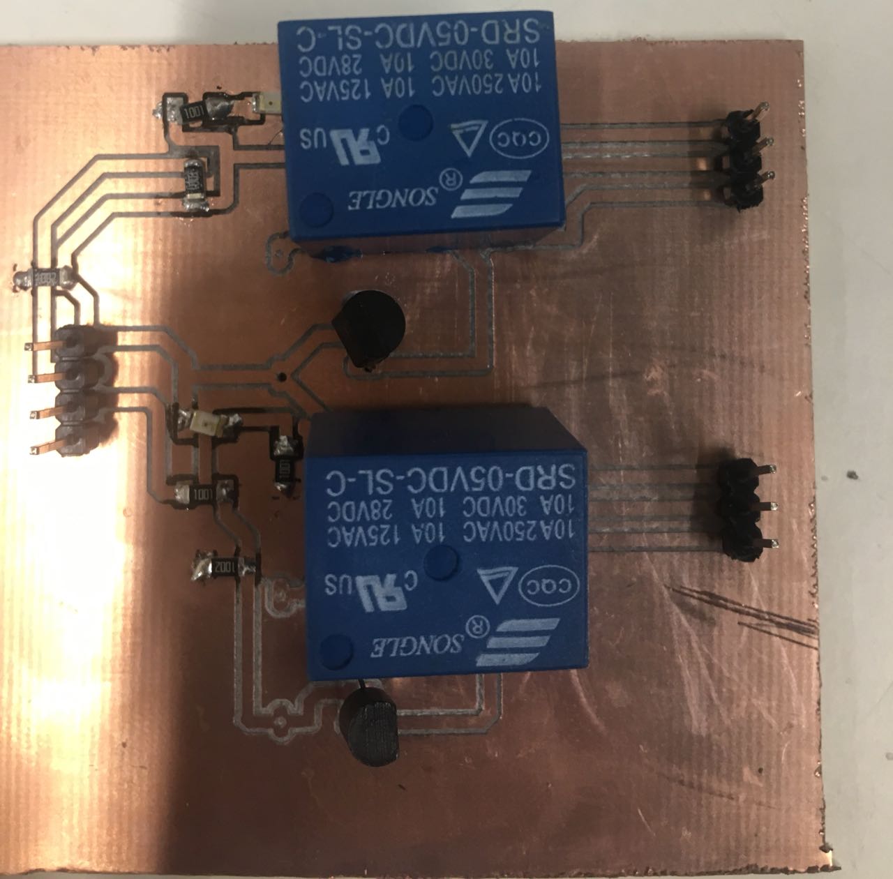
Output Device, Networking and Communications
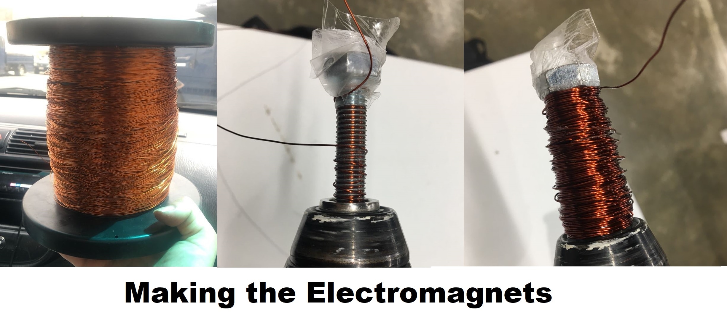
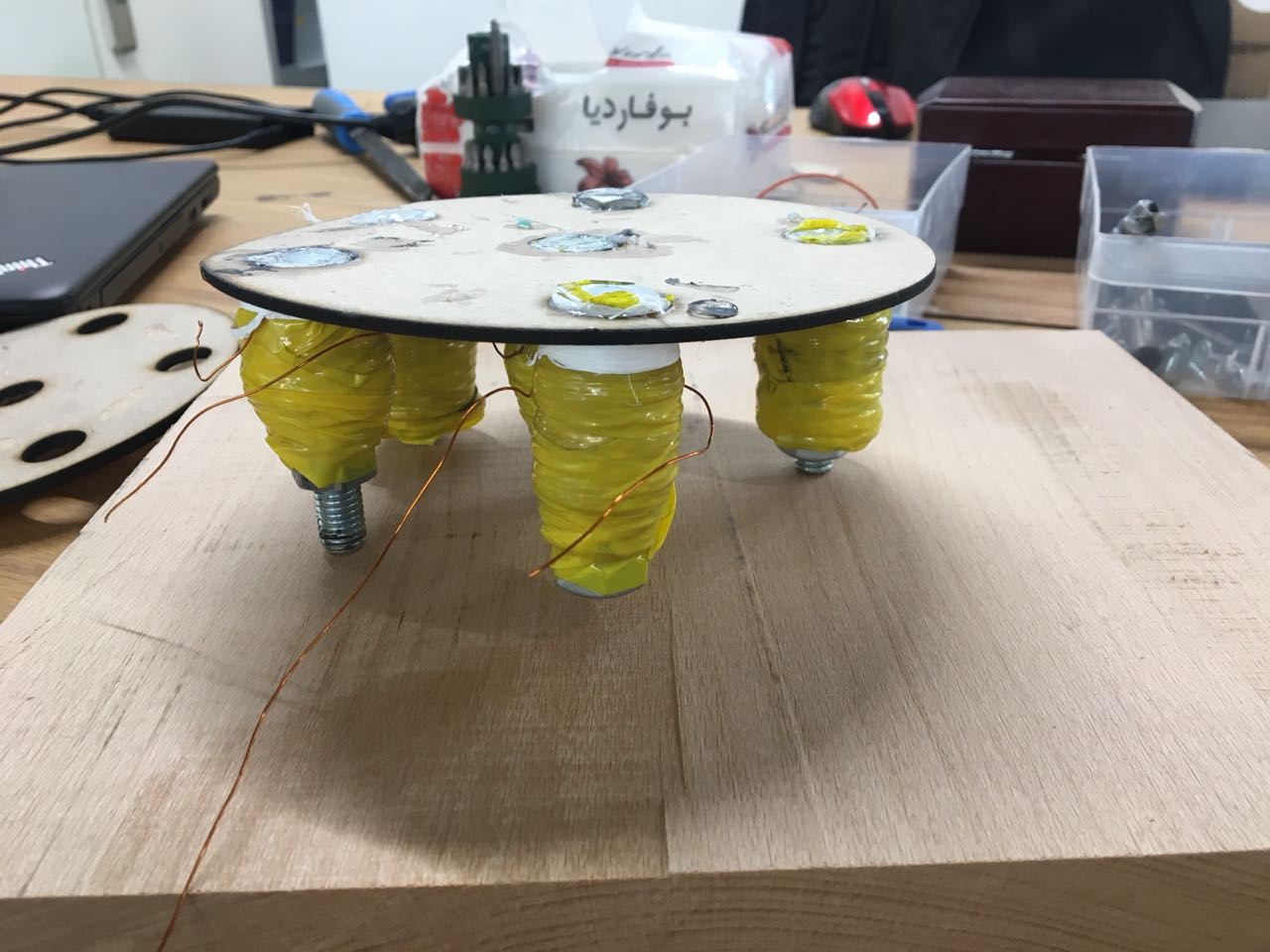
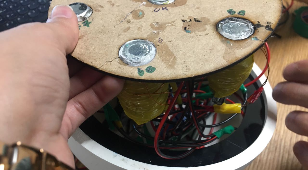
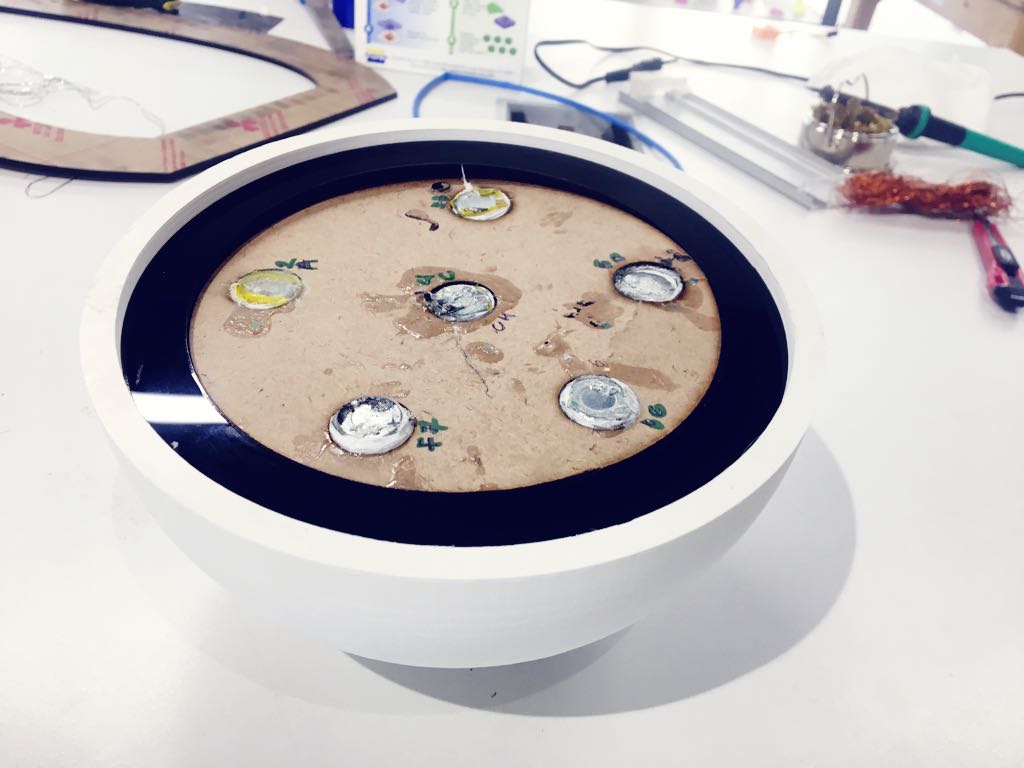
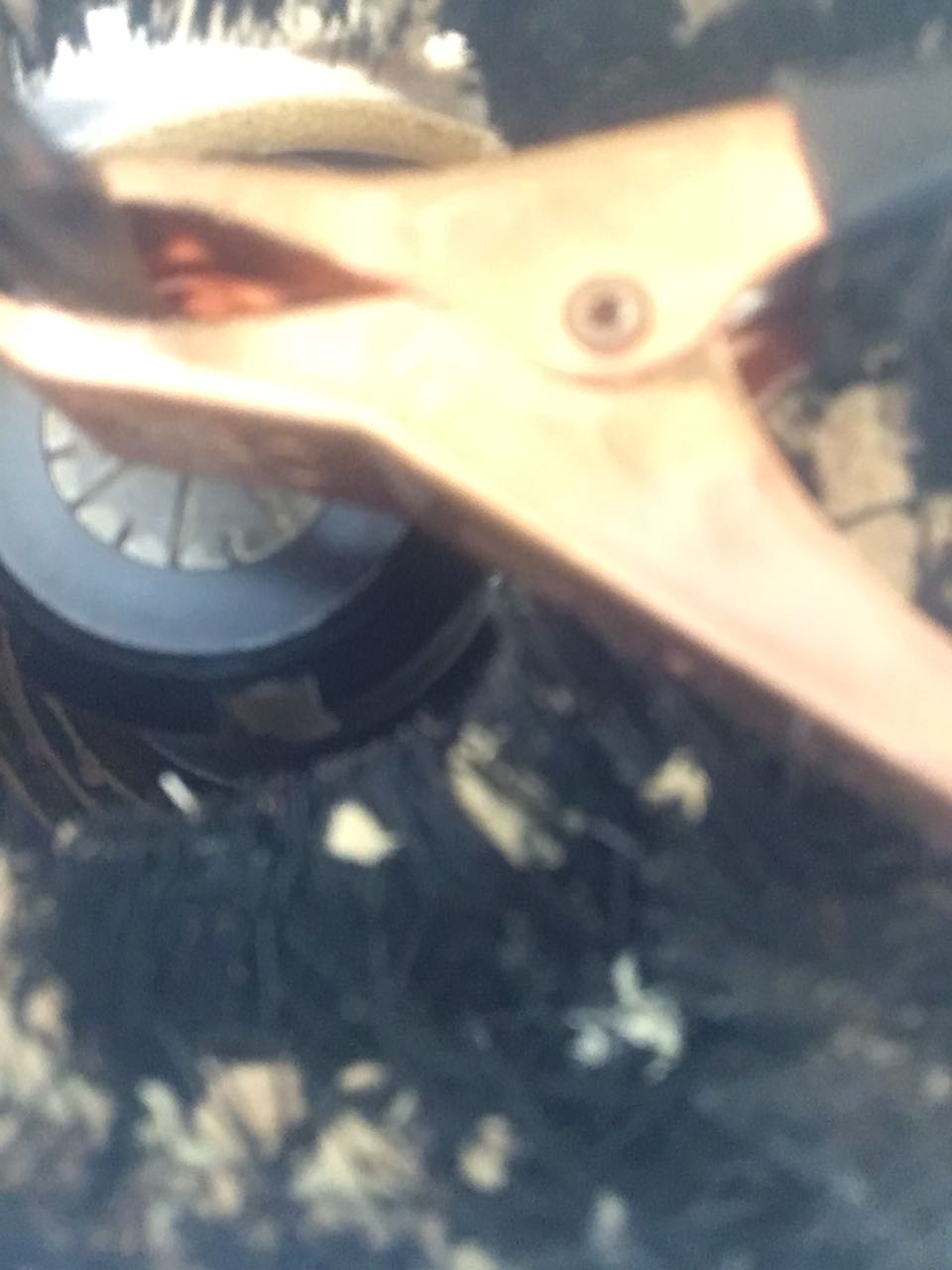
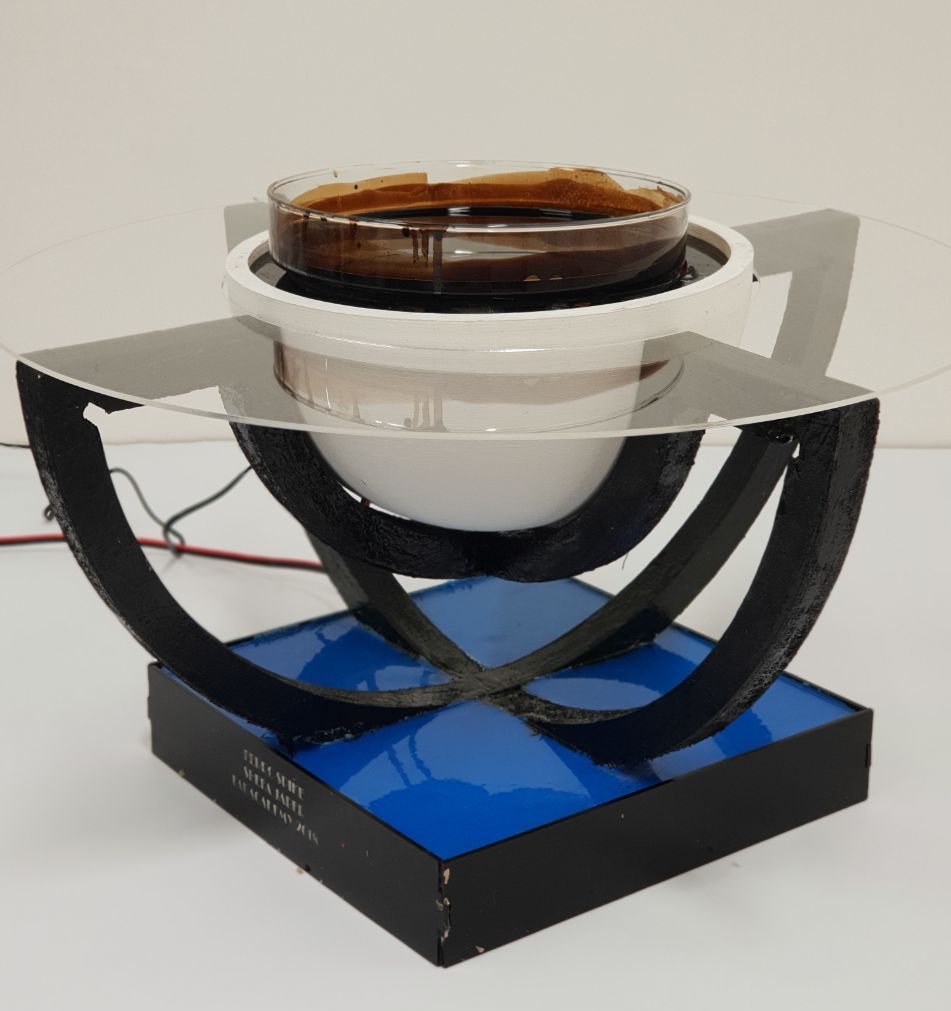
Electromagnet
The main factors that affect the strength of an electromagnet are:
Number of turns on the coil of wire around the core.
Strength of the current applied.
The material of the coil.
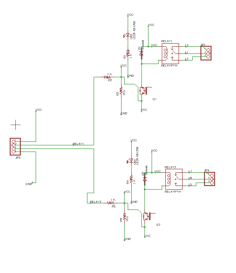
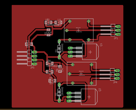
Connect the electromagnet with my board.The code is seen below.
#include <SoftwareSerial.h>

SoftwareSerial mySerial(0,1); // RX, TX
char x;

void setup() {
  // put your setup code here, to run once:
pinMode(10,OUTPUT);
pinMode(9,OUTPUT);
pinMode(8,OUTPUT);
pinMode(7,OUTPUT);

pinMode(6,OUTPUT);
pinMode(5,OUTPUT);
mySerial.begin(9600);
Serial.begin(9600);

}
int d =50;
void loop() {
  // put your main code here, to run repeatedly:
if(mySerial.available())
x = mySerial.read();

if(x == '1')
{

digitalWrite(10,0);
digitalWrite(9,0);
digitalWrite(8,0);
digitalWrite(7,1);
digitalWrite(6,1);
digitalWrite(5,1);
delay(d);
Serial.println("1");
}

if(x == '2')
{
digitalWrite(10,1);
digitalWrite(9,1);
digitalWrite(8,0);
digitalWrite(7,0);
digitalWrite(6,0);
digitalWrite(5,1);
delay(d);
Serial.println("2");
}

if(x == '3')
{
digitalWrite(10,1);
digitalWrite(9,1);
digitalWrite(8,0);
digitalWrite(7,1);
digitalWrite(6,0);
digitalWrite(5,0);

delay(d);
Serial.println("3");
}

if(x == '4')
{
digitalWrite(10,1);
digitalWrite(9,0);
digitalWrite(8,0);
digitalWrite(7,0);
digitalWrite(6,1);
digitalWrite(5,1);
delay(d);
Serial.println("4");
}


if(x == 'A')
{
digitalWrite(10,0);
digitalWrite(9,0);
digitalWrite(8,0);
digitalWrite(7,1);
digitalWrite(6,1);
digitalWrite(5,1);
delay(d);
Serial.println("A");
}

if(x == 'B')
{
digitalWrite(10,1);
digitalWrite(9,1);
digitalWrite(8,0);
digitalWrite(7,0);
digitalWrite(6,0);
digitalWrite(5,1);
delay(d);
Serial.println("B");
}

if(x == 'C')
{
digitalWrite(10,1);
digitalWrite(9,1);
digitalWrite(8,0);
digitalWrite(7,1);
digitalWrite(6,0);
digitalWrite(5,0);

delay(d);
Serial.println("C");
}


if(x == 'D')
{
digitalWrite(10,1);
digitalWrite(9,0);
digitalWrite(8,0);
digitalWrite(7,0);
digitalWrite(6,1);
digitalWrite(5,1);
delay(d);
Serial.println("D");
}

if(x == 'E')
{
digitalWrite(10,1);
digitalWrite(9,0);
digitalWrite(8,1);
digitalWrite(7,1);
digitalWrite(6,0);
digitalWrite(5,1);
delay(d);
Serial.println("E");
}


if(x == 'F')
{
digitalWrite(10,0);
digitalWrite(9,1);
digitalWrite(8,0);
digitalWrite(7,1);
digitalWrite(6,1);
digitalWrite(5,0);
delay(d);
Serial.println("F");
}
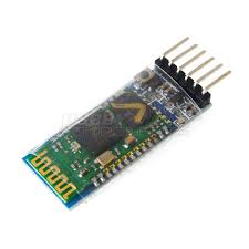
Another error appeared while first using the bluethooth receiver on the device. I uploaded the a script written with AT commands
then ran the Bluetooth receiver.
But then, when I tried sending a character like “A” for example, it wouldn’t respond as expected and it would give an error message.
It turned out, that the receiver being used is not compatible with such characters and commands
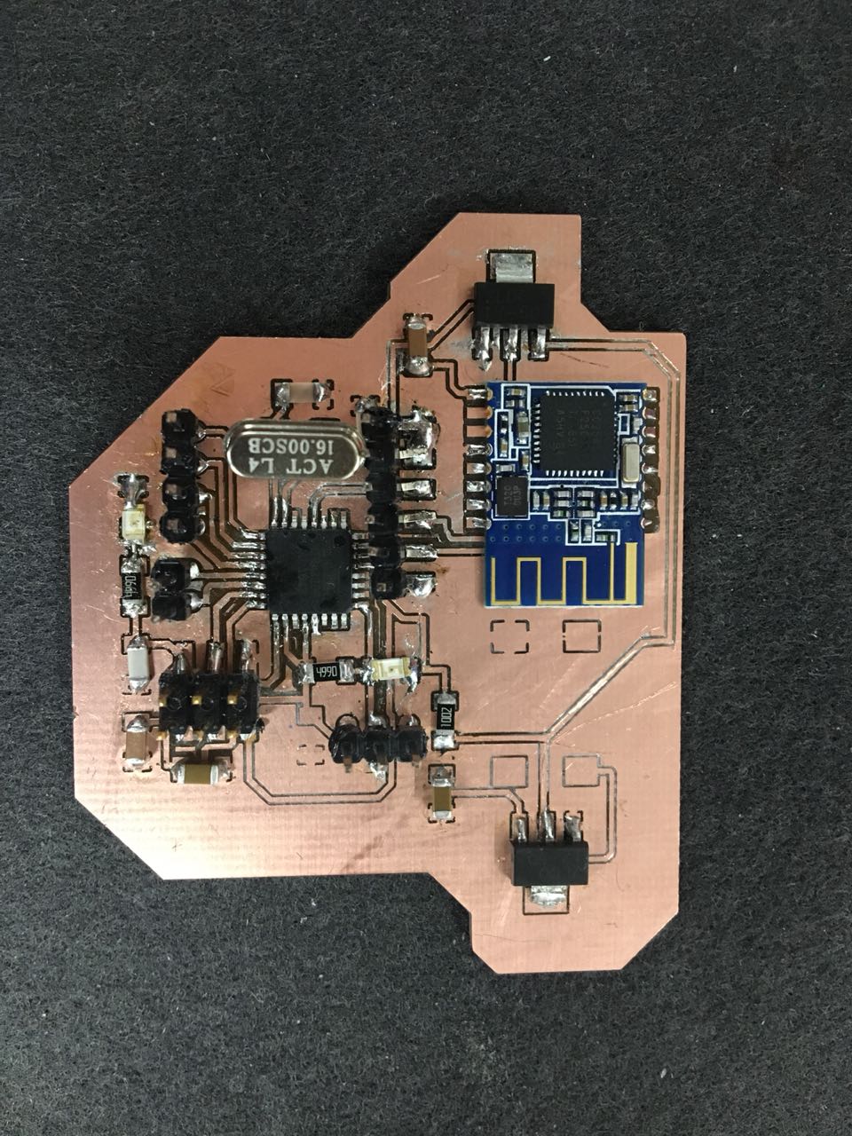
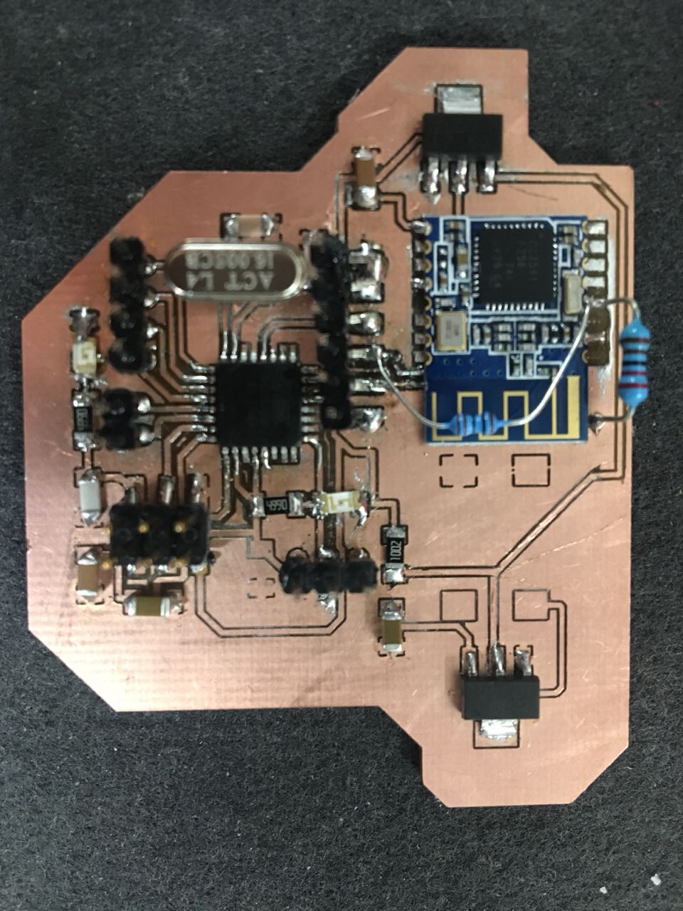
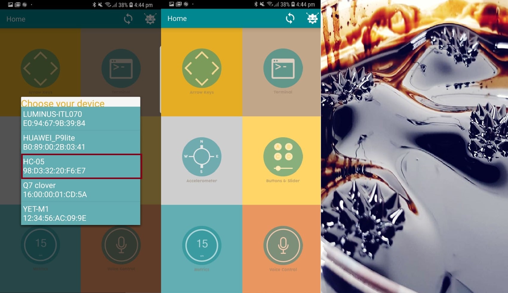
so I switched to using “HC-05”
And it worked!
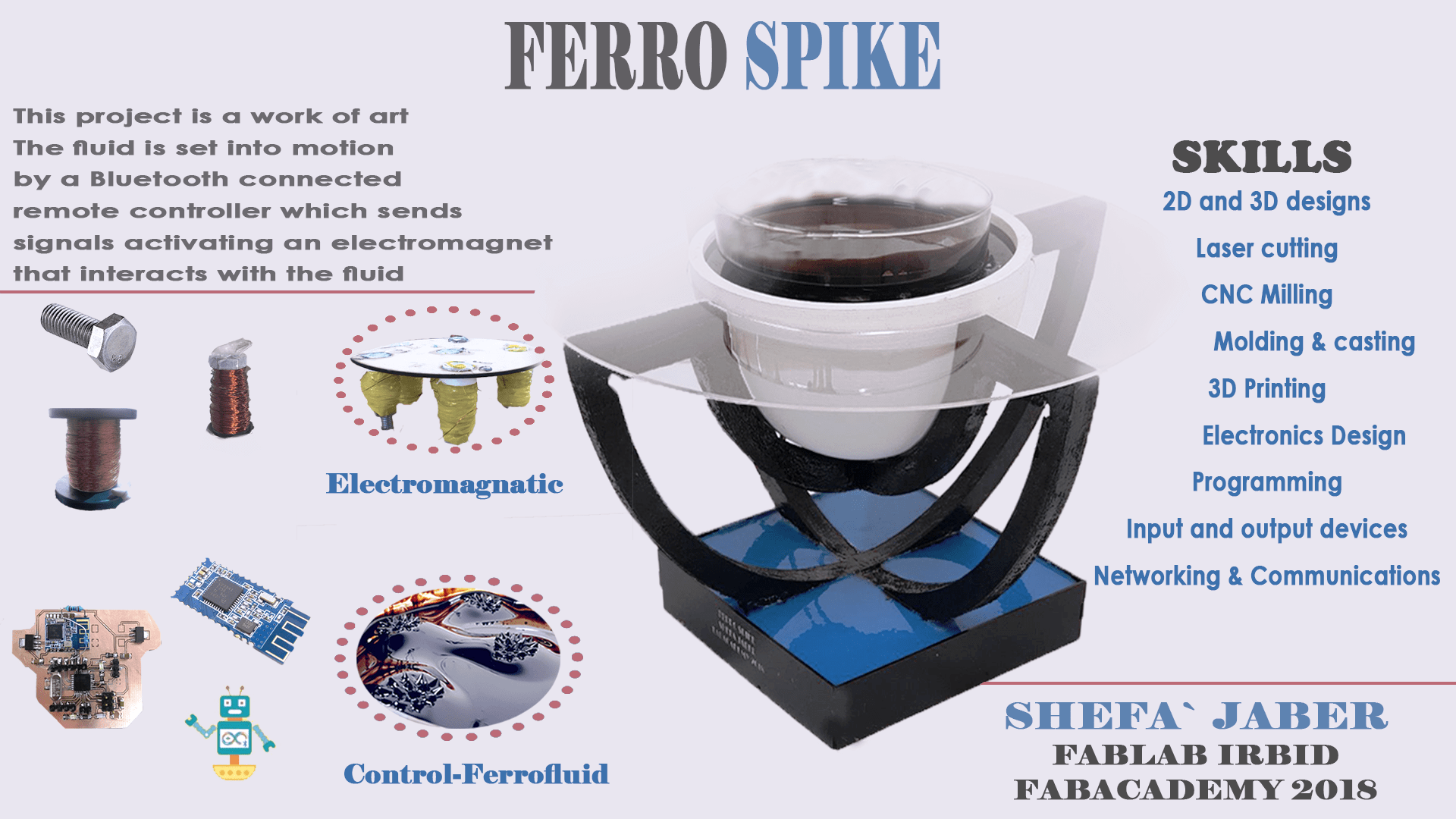
I used an Android Application called
Arduino Bluetooth Control to communicate between the bluetooth and the ferro spikes
Download All Design and Code Files:
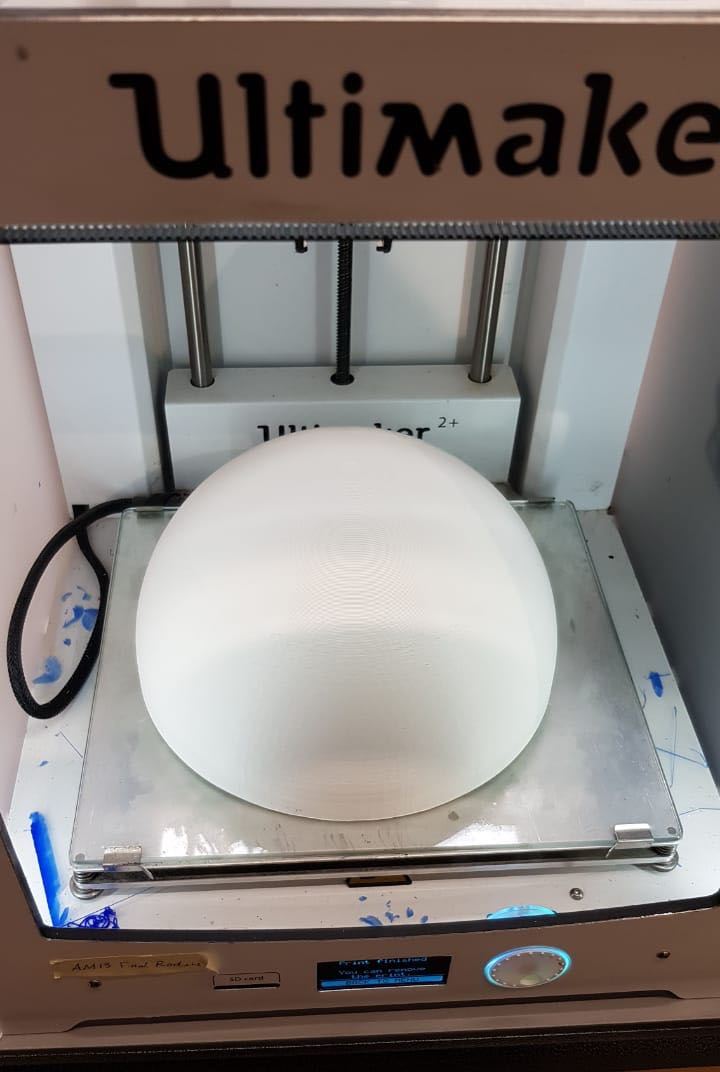
3D Design
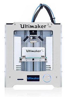
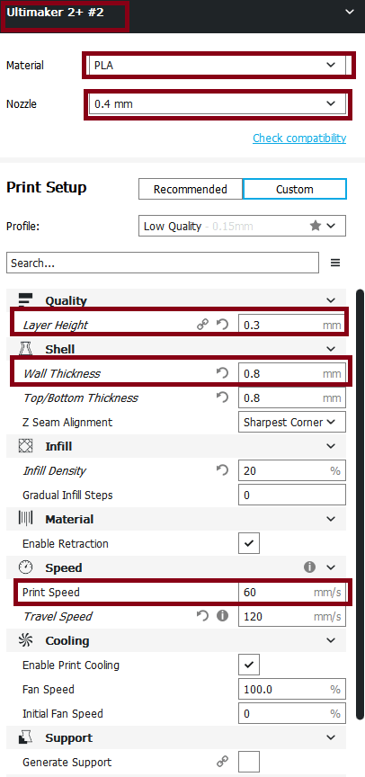
3D Printing file
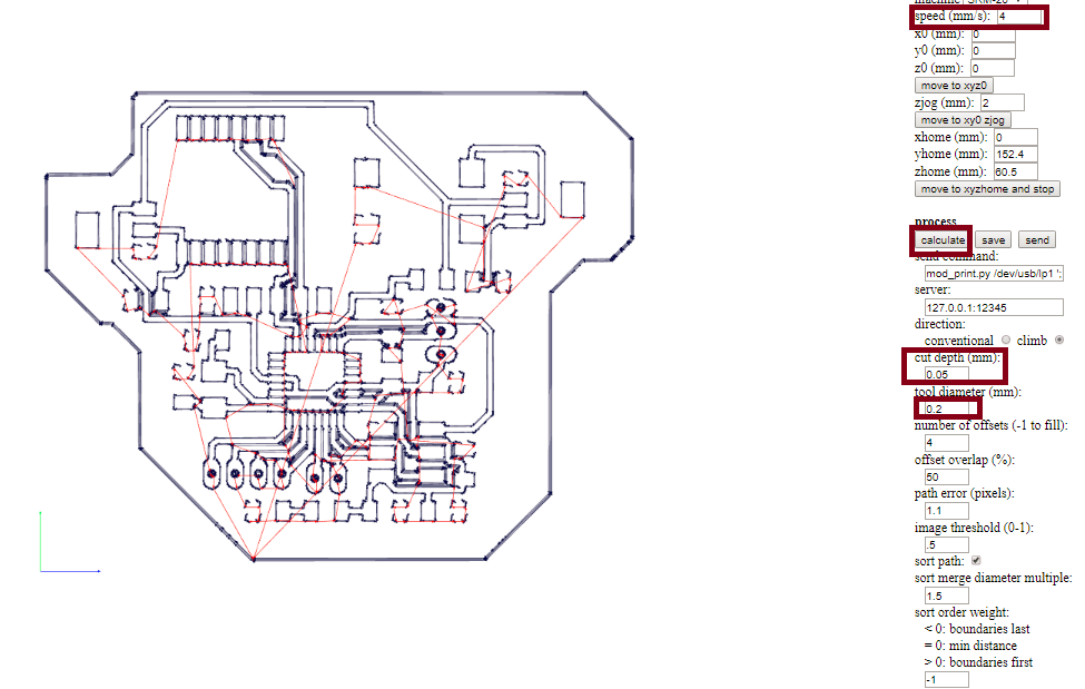
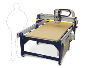
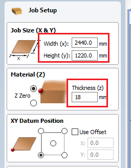
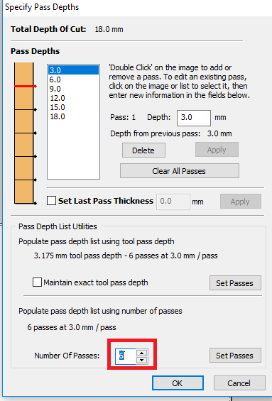
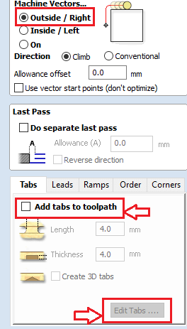
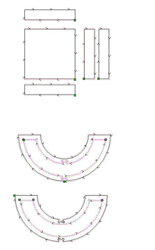
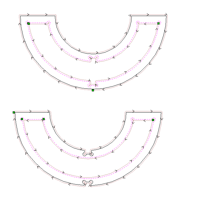
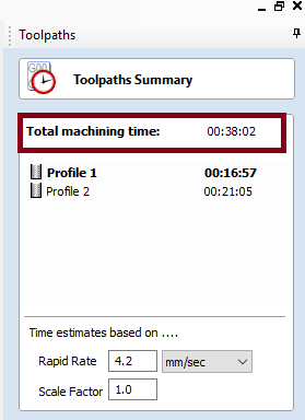
CNC file
Electromagatic
-min.jpg)

-min.png)
-min.png)
-min.png)
-min.png)
-min.png)
-min.png)
-min.PNG)
-min.png)

.png)
-min.png)
-min.png)