Output Devices Week
This week we had to test with different output devices using a board that we built on our own.
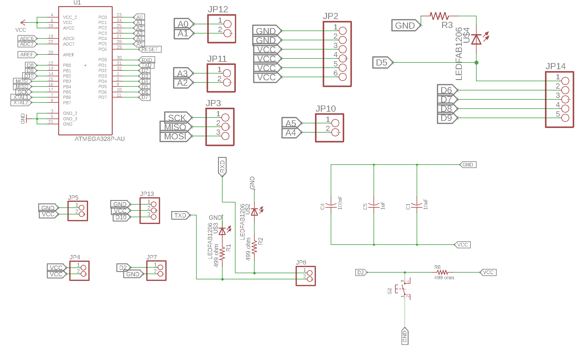
I decided to make a board that has all the needed pins for the output devices I will use near each other so I wouldn't have wires spread all over the baord making it look all ugly.
The schematics of the board is seen below
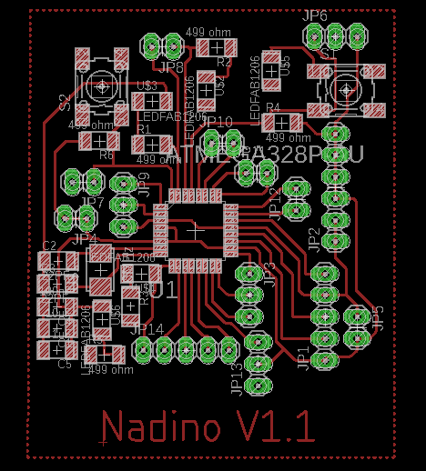
I exported it to get the inner and outer cuts then milled and soldered it.
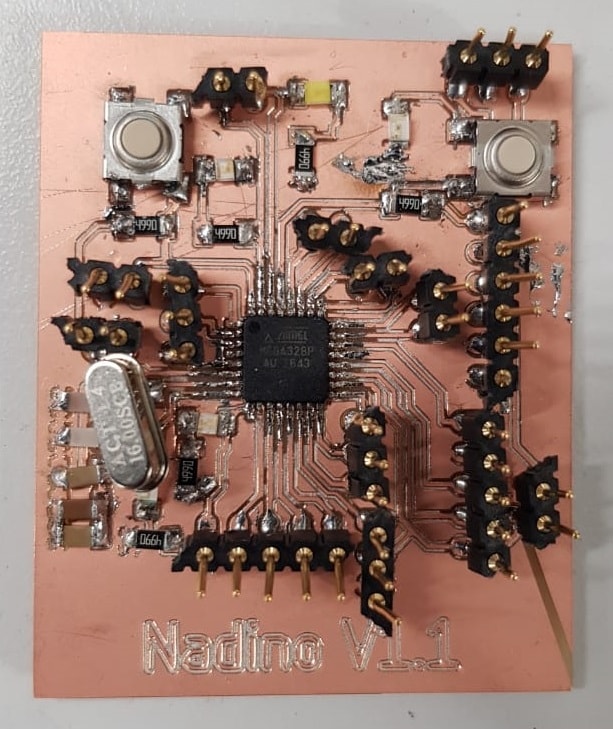
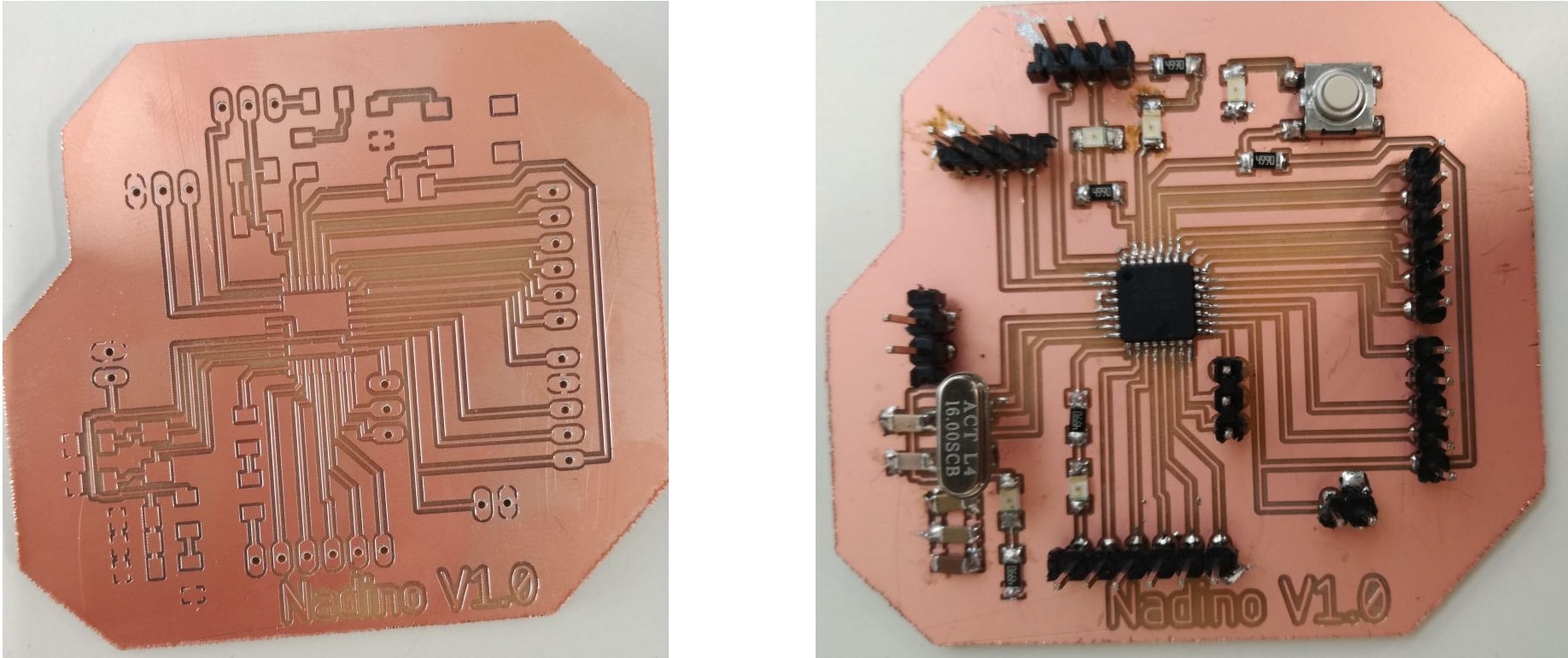
Unfortunately when I tested the traces with the multimeter, I found some short that occured while I was soldering. Also the quality of the PCB is so bad that the epoxy layer burns immediately when I try to solder components, so I decided to use the Nadino Board that I created two weeks ago since it basically operates as an Arduino and it has many pins that I can use as outputs to control output devices.
Output devices are used to control the the environment around us, you can control different devices and have them do a certain action based on an input.
Solenoid Valve
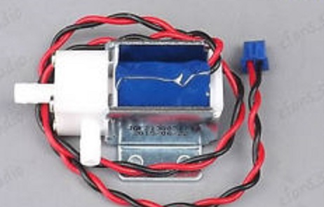
A solenoid valve is an electromechanically operated valve. The valve is controlled by an electric current through a solenoid.
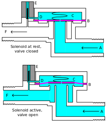
The diagram below shows the design of a basic valve, controlling the flow of water in this example. At the top figure is the valve in its closed state. The water under pressure enters at A. B is an elastic diaphragm and above it is a weak spring pushing it down. The diaphragm has a pinhole through its center which allows a very small amount of water to flow through it. This water fills the cavity C on the other side of the diaphragm so that pressure is equal on both sides of the diaphragm, however the compressed spring supplies a net downward force. The spring is weak and is only able to close the inlet because water pressure is equalized on both sides of the diaphragm. Once the diaphragm closes the valve, the pressure on the outlet side of its bottom is reduced, and the greater pressure above holds it even more firmly closed. Thus, the spring is irrelevant to holding the valve closed. The above all works because the small drain passage D was blocked by a pin which is the armature of the solenoid E and which is pushed down by a spring. If current is passed through the solenoid, the pin is withdrawn via magnetic force, and the water in chamber C drains out the passage D faster than the pinhole can refill it. The pressure in chamber C drops and the incoming pressure lifts the diaphragm, thus opening the main valve. Water now flows directly from A to F. When the solenoid is again deactivated and the passage D is closed again, the spring needs very little force to push the diaphragm down again and the main valve closes. In practice there is often no separate spring; the elastomer diaphragm is molded so that it functions as its own spring, preferring to be in the closed shape.
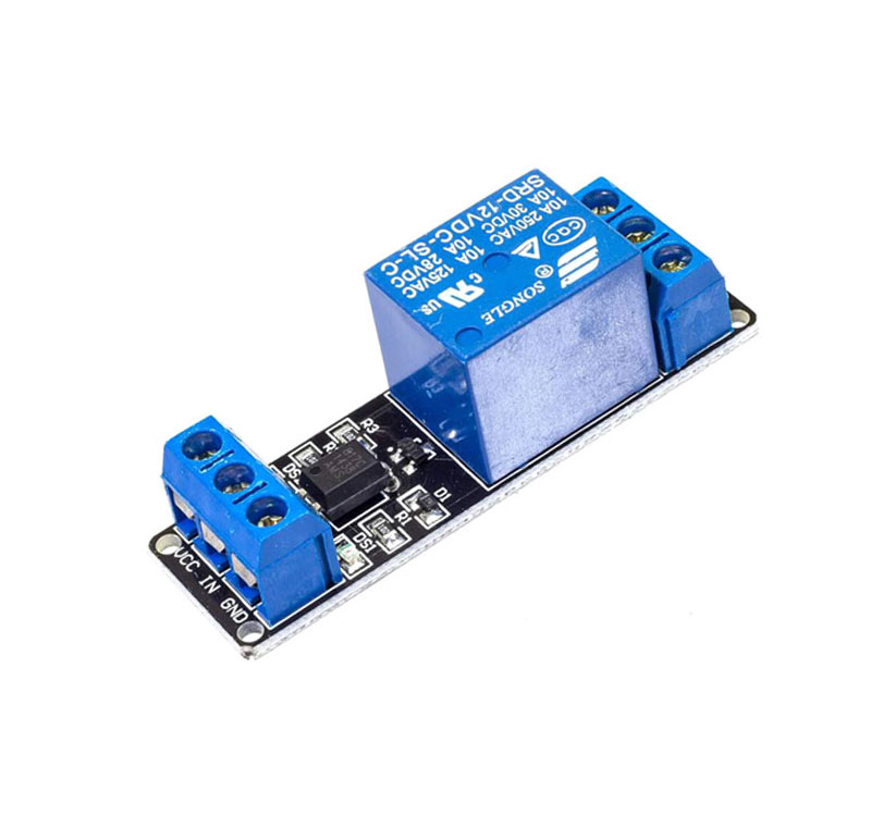
To control the solenoid, I had to connect it to a relay.
A relay is essentially a switch that is operated electrically rather than mechanically. Although there are various relay designs, the ones most commonly found in low voltage auto and marine applications are electro-mechanical relays that work by activating an electromagnet to pull a set of contacts to make or break a circuit.
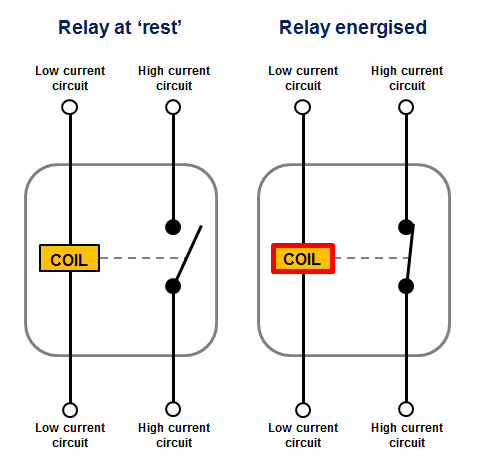
Relays consists of a coil, When the coil is supplied with voltage a magnetic field is generated around it which pulls the hinged armature down onto the contact. This completes the 'high' current circuit between the terminals and the relay is said to be energised. When voltage is removed from the coil terminal the spring pulls the armature back into it's 'at rest' position and breaks the circuit between the terminals. So by applying or removing power to the coil (the low current circuit) we switch the high current circuit on or off.
I connected my relay to my Nadino Board as seen below.
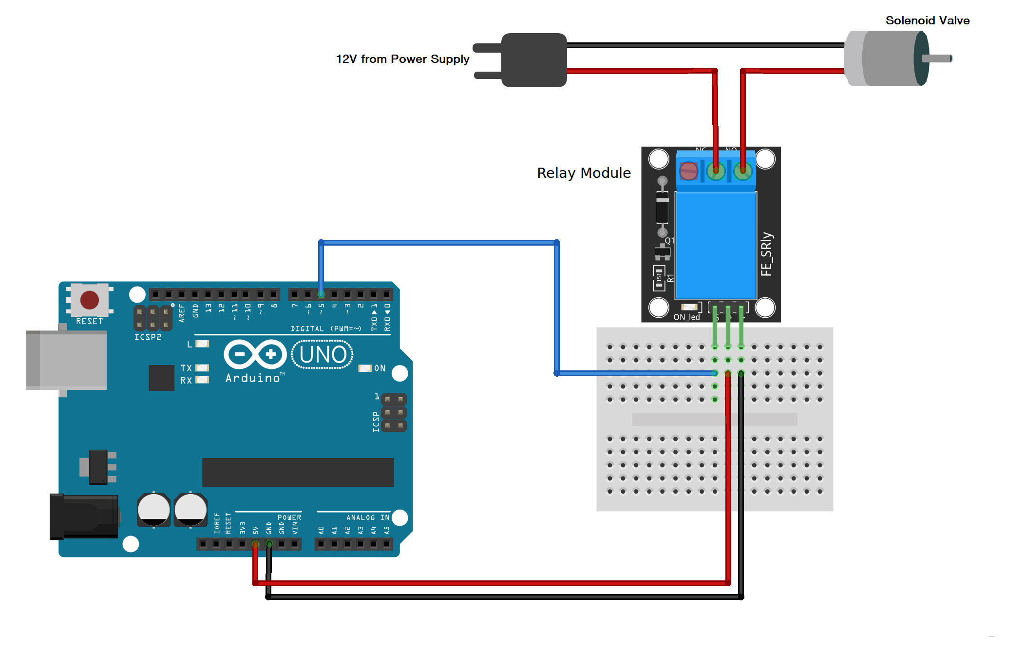
Since I didn't have a pump to connect to the solenoid valve, I wanted to see if everything actually works, so I connected a fan instead of the solenoid and it did work!
The code I wrote is pretty simple and it's seen below:
#define relay 5
void setup() {
      // put your setup code here, to run once:
      pinMode(relay, OUTPUT);
}

void loop() {
      digitalWrite(relay, HIGH);
      delay(5000);
      digitalWrite(relay,LOW);
      delay(5000);
}
Making a 12V Control Board Using MOSFET
Instead of using relays which can slow down the response of my device and greatly increase the cost of manufactuirng, MOSFETs are a better option.
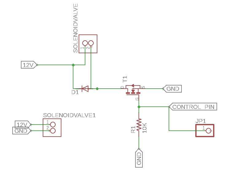
So I designed the smallest board I have made so far that consists of a MOSFET, a diode, pin headers and a single resistor.
The schematics for it is seen below.
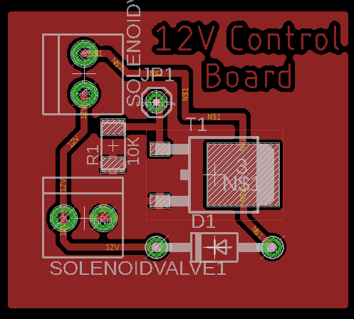
Routing this board was the easiest routing job I've done! Of course it has very few components.
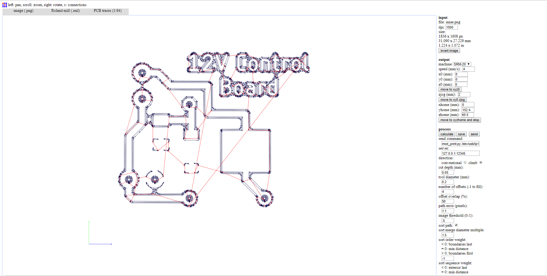
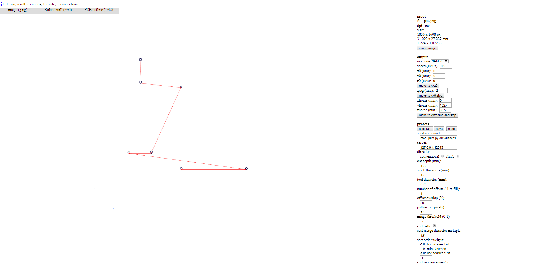
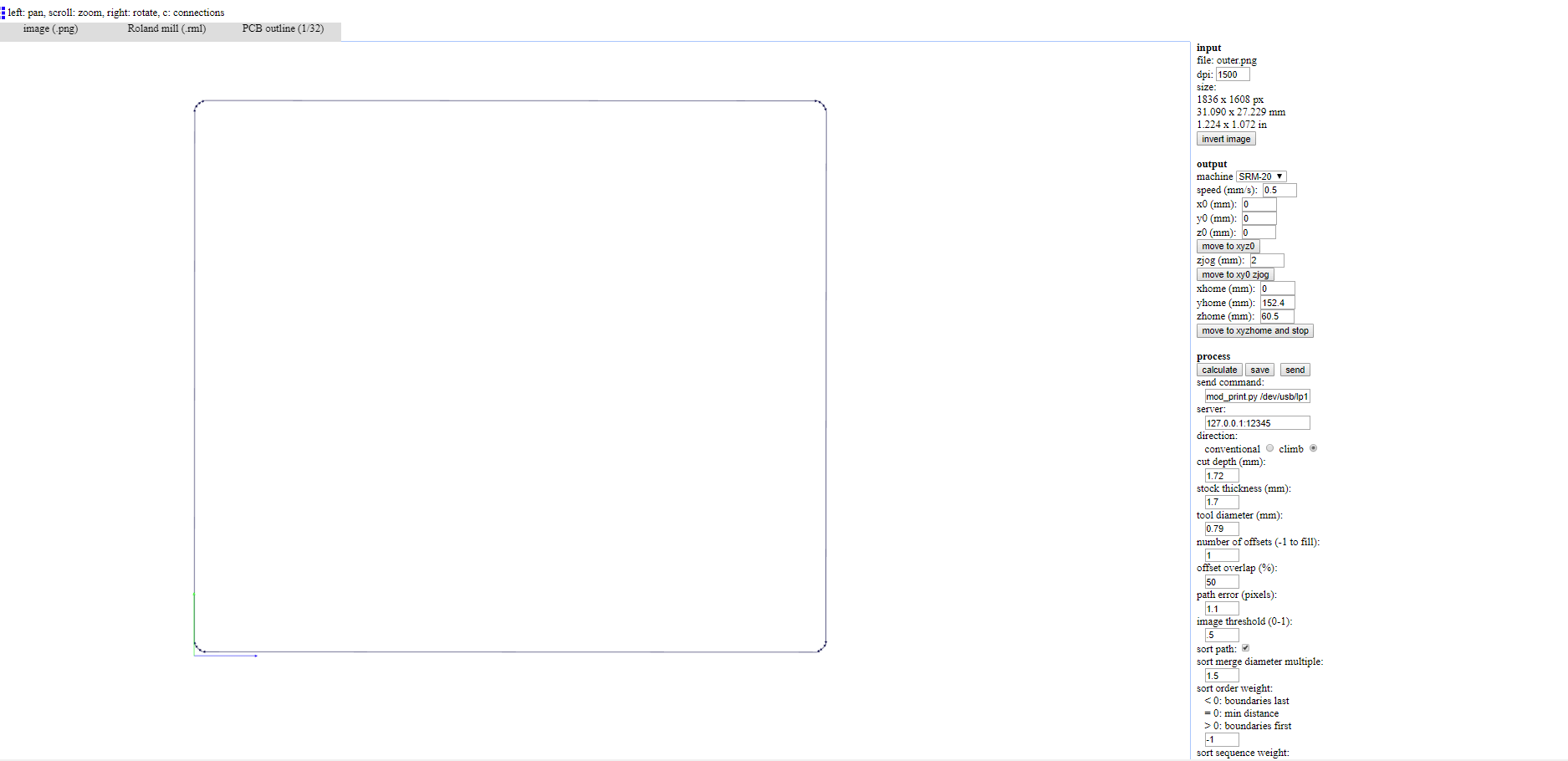
I then exported it into inner traces and pads and set the settings as seen below.
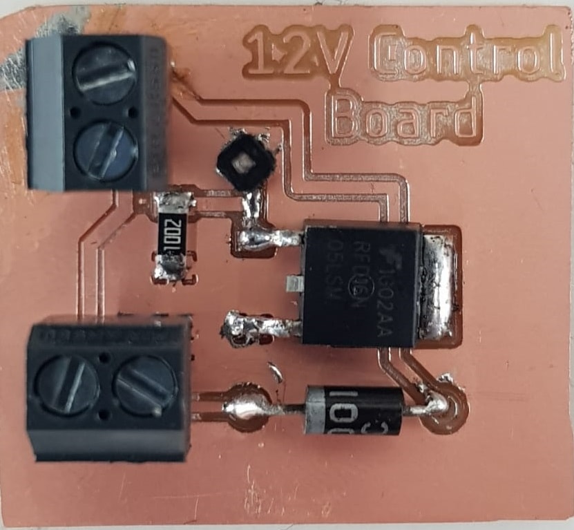
Here's what my board looks like after soldering the few components it has.
I connected it instead of the relay to my Nadino board and used the exact same code as before. The video for how it works is seen below. Pay attention to the LED that lights up when the pin is set to high and turns off when it's set to low as the delay was only 5 seconds and not enough to completely show the fan is off.
I used a fan to prove it works cause a solenoid valve only has a sound that might not be heard in the video.
DC Motor
A DC motor is any of a class of rotary electrical machines that converts direct current electrical energy into mechanical energy.
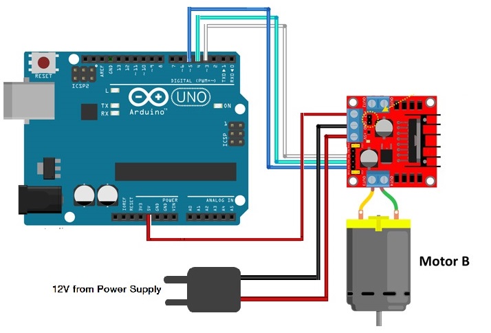
To control a 12V DC motor using an Arduino or in this case a Nadino you need an H-Bridge.
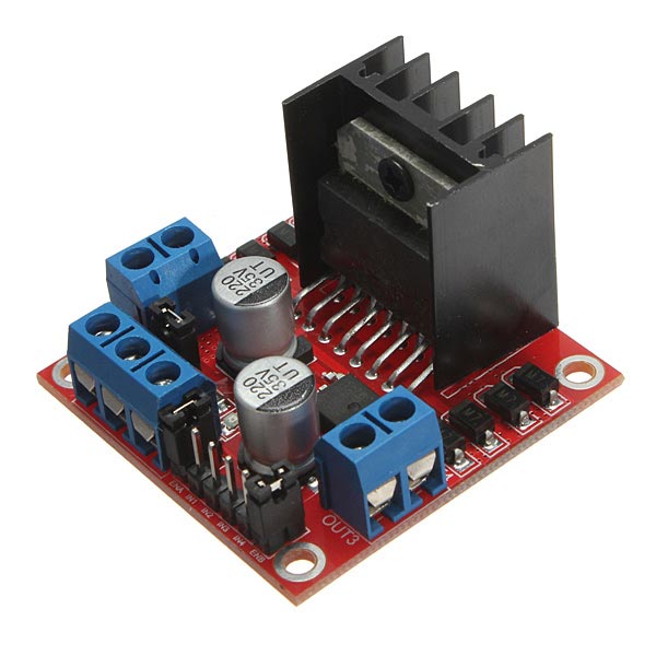
An H bridge is an electronic circuit that enables a voltage to be applied across a load in opposite direction. These circuits are often used in robotics and other applications to allow DC motors to run forwards or backwards.
The H-bridge I used can control 2 motors at the same time, I used it to control only one.
For each motor there are 3 pins to control it, which are:
- Enable: This controls the speed of the motor and it should be connected to a PWM pin on the board.
- Input 1: This is used to control the direction the motor rotates in (CW or CCW). If this is set to 1, Input 2 should be set to zero.
- Input 2: the same as input one, if you set this you'd have to zero input one and it will reverese the direction the motor rotates in.
Since the DC motors I had were 12V DC motors, I also had to use an external power supply of 12V connected to the H-Bridge's VCC amp; GND.
The connections are seen in the below circuit diagram.
I programmed the DC motor to rotate in one direction fast then to stop, slow down and reverse the direction of rotation as seen in the below video.
The code I wrote is seen below:
#define pin2 3
#define pin1 4
#define enable 5

void setup() {
      pinMode(pin1, OUTPUT);
      pinMode(pin2, OUTPUT);
      pinMode(enable, OUTPUT);
      delay(1000);
 }
void loop() {
      //Make motor turn in one direction with a speed of 500
      digitalWrite(pin1,1);
      digitalWrite(pin2,0);
      analogWrite(enable,500);

      delay(1000);

      //Make the DC Motor stop
      digitalWrite(pin1,0);
      digitalWrite(pin2,0);
      analogWrite(enable, 0);
      delay(1000);

      //Reverse the direction of rotation and make the motor go slower
      digitalWrite(pin1,0);
      digitalWrite(pin2,1);
      analogWrite(enable, 50);
      delay(1000);

}
Problems
Other than the rookie mistake I did while soldering the output board I designed for this week, everything went fine. Luckily I created another board that I could use a couple of weeks ago.
You can download my files here.
