Networking & Communications Week
This week we had to work on letting 2 processors communicate with each other. I chose to have the two boards I built in previous weeks communicate with each other.
Communicating with Attiny44
I decided to let the commercial arduino talk to the attiny44 board that I created two weeks ago.
The board I designed had a built in LED and Button so I programmed it to send a message to the Arduino and light the LED when the button is pressed.
The code I wrote for the Attiny is seen below.
Attiny44 doesn't have a hardware serial so I used the library Software Serial.
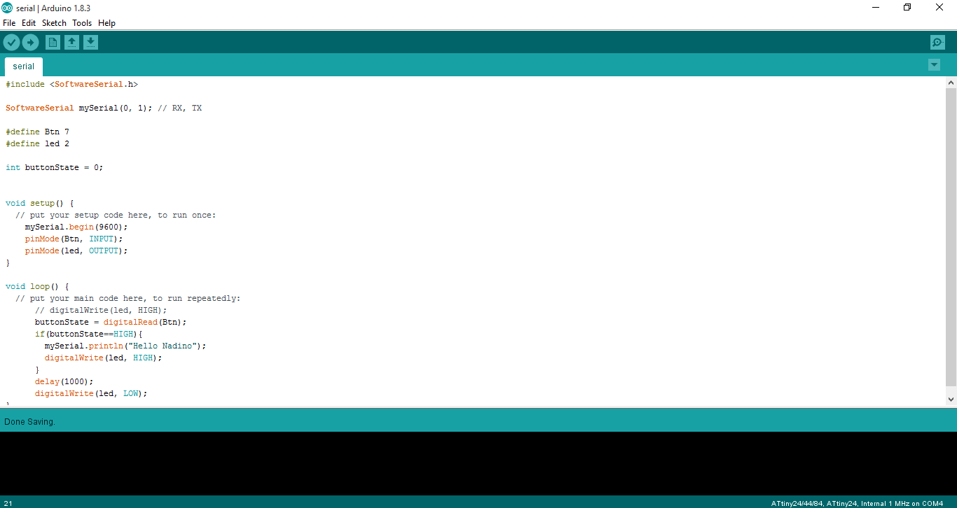
The code for the arduino is quite simple, it just reads the serial port and prints the message on the Serial Monitor.
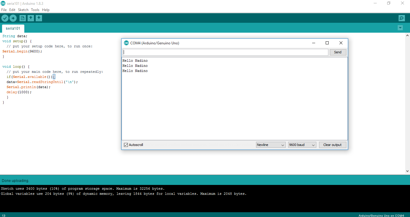
The below video shows that the arduino receives the message when I press the button.
Serial Communication with Nadino
For the Nadino I wanted to have it blink an LED when it receives a certain message, so I programmed also on software serial library becuase the RX & TX of the board is messed up cause I wanted to act smart and add an LED to it but I forgot that LED only let's signals pass only in one direction.
The code for the Nadino Board is seen below.
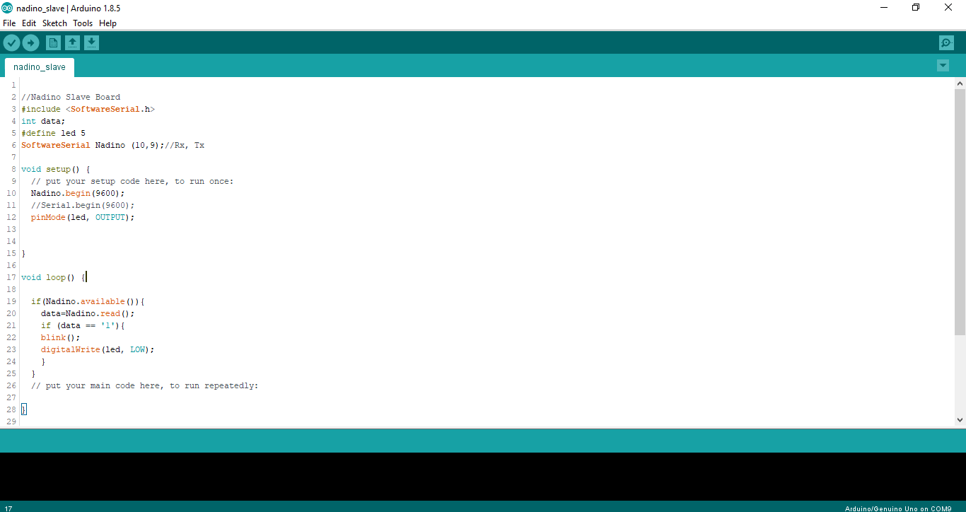
For the Arduino, the code is quite simple it just sends whatever I write on the serial monitor to the Nadino Board.

Here's what happens when the I send a message is sent from the Arduino to the Nadino.
Designing the Wifi
I designed a WiFi board based on the design available on the FabAcademy website, the schematics is seen below.

The Board is seen below.
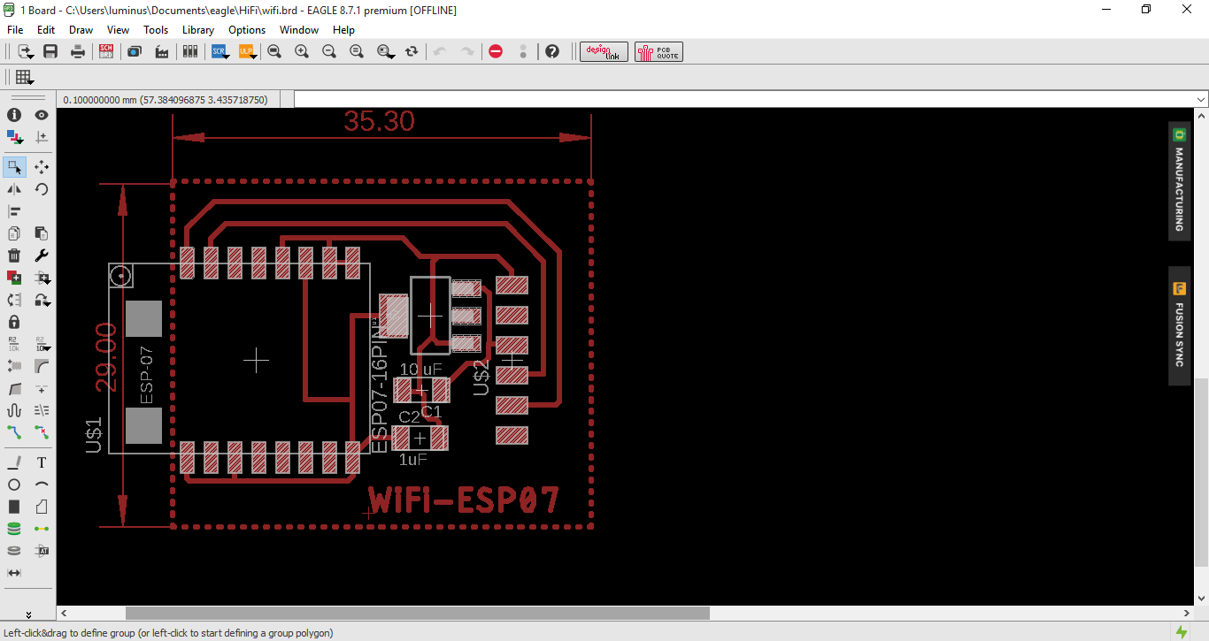
The finished board is seen below.
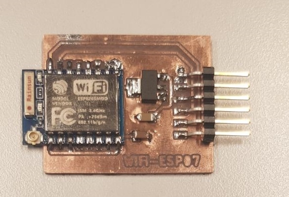
To program the WiFi board, I had to get acquainted with AT Commands. There are several tutorials available on the internet on it. I found this one very useful.
First I used AT to test if my module is responding, if it was, it should respond with OK. After that I used AT+CWLAP to list all available access points to connect to.
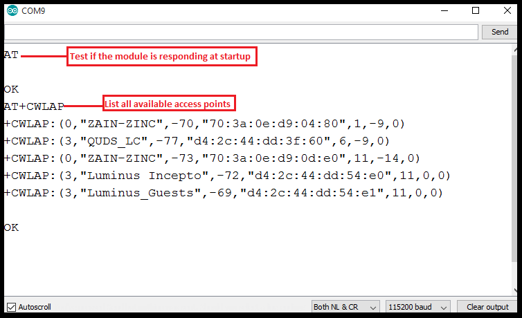
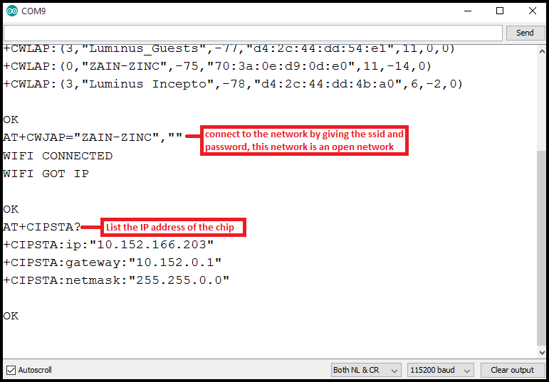
After that I used AT+CWJAP="ssid","password" to connect to a network.
Then I used AT+CIPSTA?to get the IP Address of the chip.
A little background on what an IP Address is:
We as humans can identify each other by our names, computers are not the same. It's not like my computer who's also called Nadine knows the computer of my coworker by name.
The internet uses Internet Protocol Addresses referred to as IP address to send and receive data.
There are two types of IP addressing which are:
- IPv4: which is commonly used. It uses 32 bits that are divided into 4 segment of equal size, 8 bits each. The binary numbers are then converted into decimal and each part is separated by a point.
An example address is: 195.195.92.161.
The IP address is also divided into 2 parts which are the Network ID and the Host ID. The network ID's size depends on the class of the IP address used. There are 5 different classes which are: A, B, C, D and E.
Classes A, B and C are used for allocating IP addresses. Class D is used for multicasting (sending data to groups either one-to-many or many-to-many). Class E is reserved for experimentation.
The difference between Classes A, B and C is the size of the network ID.- Class A: the network ID is 8 bits and starts with a zero as follows: 0NNNNNNN.HHHHHHHH.HHHHHHHH.HHHHHHHH.
- Class B: the network ID is 16 bits abd starts with 10 as follows: 10NNNNNN.NNNNNNNN.HHHHHHHH.HHHHHHHH.
- Class C: the network ID is 24 bits and starts with 110 as follows: 110NNNNN.NNNNNNNN.NNNNNNNN.HHHHHHHH.
- Class A: 255.0.0.0
- Class B: 255.255.0.0
- Class C: 255.255.255.0
How do we distinguish between the network ID and the host ID?!
For that we use Subnet Masks! The subnet mask is basically replacing all the network ID with ones which gives us the following subnet mask for the classes:
Broadcast address which is when you set the host address to ones or (255). And this means you're sending the data to every host on the network.
Network address is when you set the host address to zeros. - IPv6: IP version 6 was actually introduced in the mid 90s but just recently received attention cause IP version 4 is actually running out! WHAAAT?! Yup we've consumed over 4 billion IP addresses that were provided by IPv4.
The main difference is that IPv6 provides waaay more IP addresses (even if each and everyone on the planet gets his/her own IP address will still have some left :) ).
IPv6 is 128 bits long! and is represented in Hexadecimal. It is divided into 8 segemnets and each segment is separated by a colon (:). An example address is 2001:0DB8:85A3:0000:0000:8A2E:0370:7344.
So which IP address do you have?! You probably have something called Private IP Address. What?! Another type!!
Instead of having devices inside a home or business network each use a public IP address, of which there's a limited supply (we ran out of those), private IP addresses provide an entirely separate set of addresses that still allow access on a network but without taking up a public IP address space.
You see, your router has a public IP address since it's capable of Network Address Translation (NAT) but all the other devices connected to the router has a private IP address.
The Internet Assigned Numbers Authority (IANA) reserves the following IP address blocks for use as private IP addresses:
- 10.0.0.0 to 10.255.255.255
- 172.16.0.0 to 172.31.255.255
- 192.168.0.0 to 192.168.255.255
The first set of IP addresses from above allow for over 16 million addresses, the second for over 1 million, and over 65,000 for the last range.
And that's pretty much IP Addressing in a few paragraphs! Can you guess if the chip has a private or public IP address?! You guessed right! It's a private IPv4 IP address :)
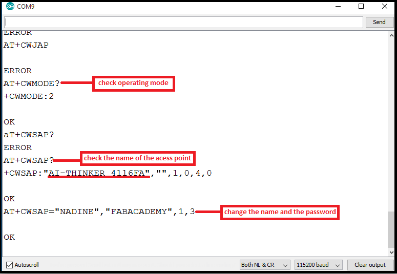
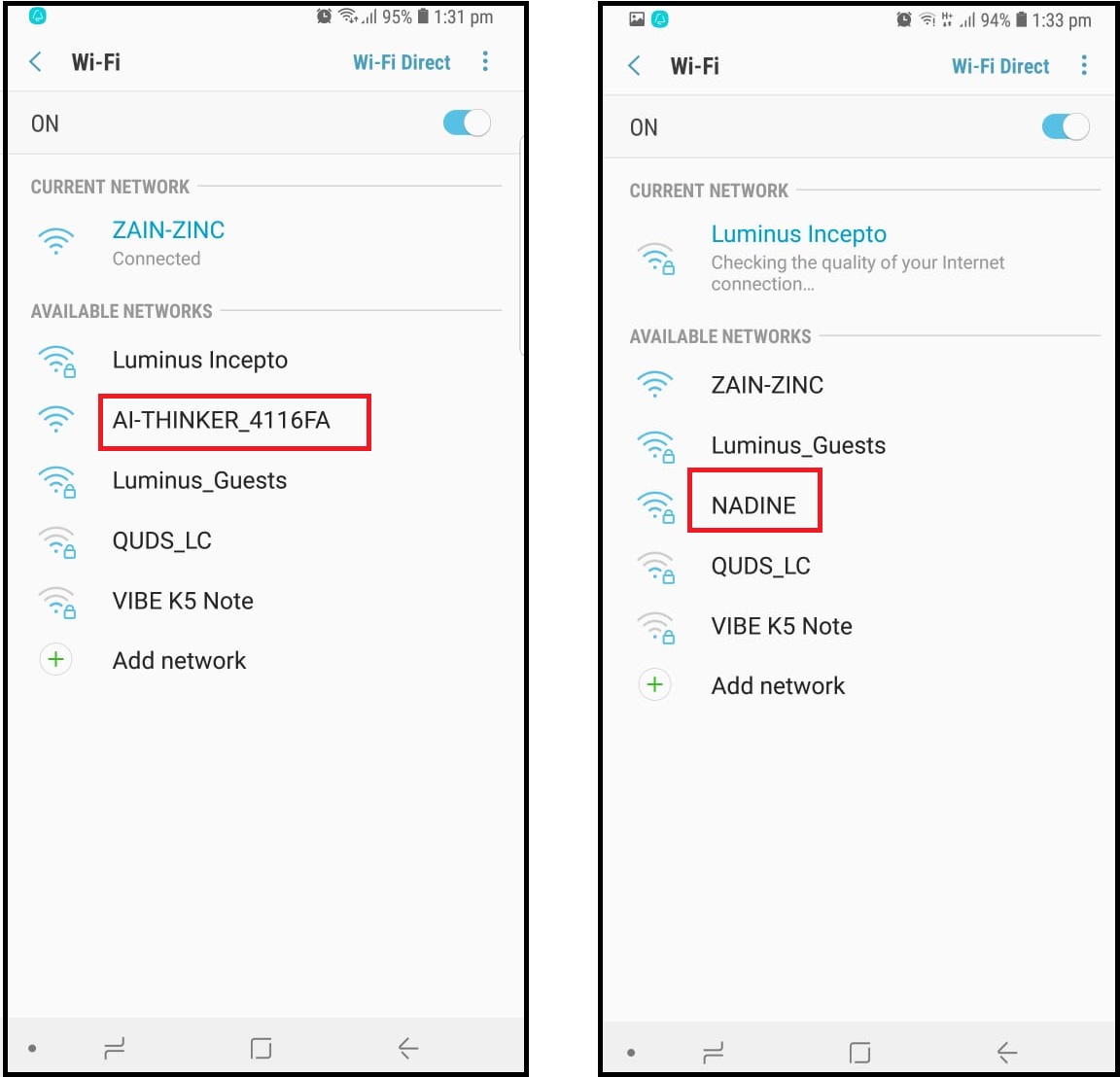
Next, I wanted to turn my wifi into an access point and have my mobile connect to it. To do that, I had to switch my module's operating mode from client to server. To do that I used AT+CWMODE=2 where 1 is client, 2 is host and 3 is dual.
Then I used AT+CWSAP? to check the name of the network.
Using Bluetooth HC-05
I also decided to use a bluetooth module. For the bluetooth, I didn't have the time to design my own board so I just used a commercial one.
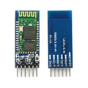
To use this bluetooth, I programmed my atmega328P board to receive data from the bluetooth using software serial and depending on the data received it controls an LED. The code is seen below.
#include <SoftwareSerial.h>
SoftwareSerial LED (3,2); // Tx first then Rx
#define led 5
void on();
void off();


void setup() {
  // put your setup code here, to run once:

  LED.begin(9600);
  Serial.begin(9600);
  pinMode(led, OUTPUT);
  delay(1000);

}
void loop() {
  // put your main code here, to run repeatedly:
  if (LED.available()){ //if data is received
    char input=LED.read();
    Serial.write(input);

    switch (input){
     case '1':
       on();
       break;
      case '2':
       off();
       break;
    }
  }
}

void on(){
  digitalWrite(led,1);
  LED.print("LED is ON");
}
void off(){
  digitalWrite(led,0);
  LED.print("LED is Off");
  }
To send data via bluetooth to my board, I downloaded a mobile application called Bluetooth Terminal HC-05 and used it to send an recieve data.
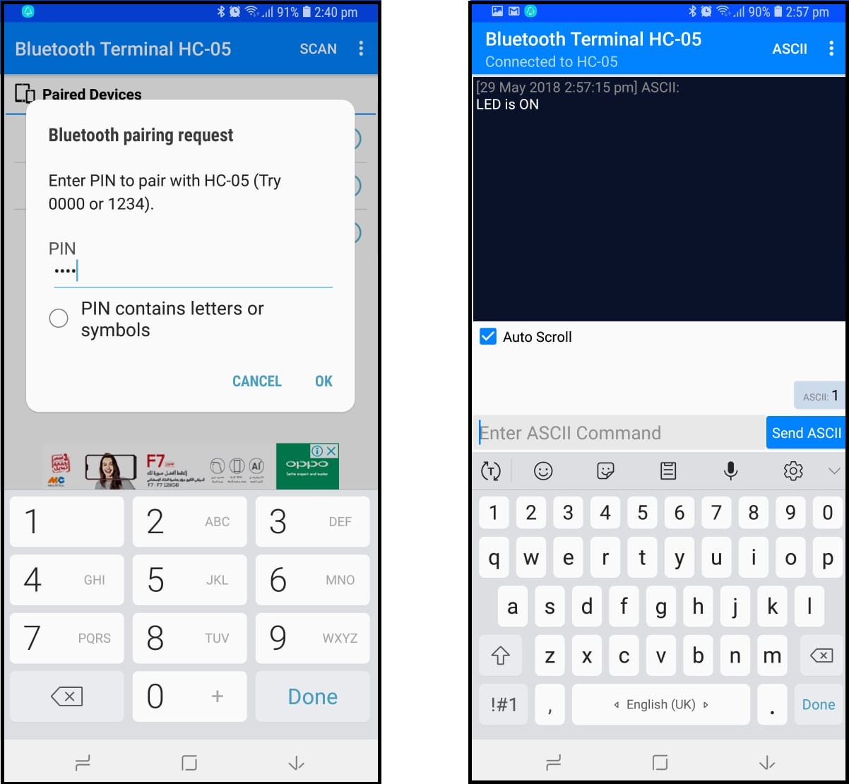
The video is seen below.
You can download my files here.