Input Devices Week
This week we had to test with different input devices using a board that we built on our own. I decided to use the Nadino Board that I created two weeks ago since it basically operates as an Arduino and it has many pins that I can use as inputs to read from input devices.
Input devices are used to sense the environment around us, you can sense and track different parameters using sensors and have them create a certain action based on that input.
Light Dependant Resistor
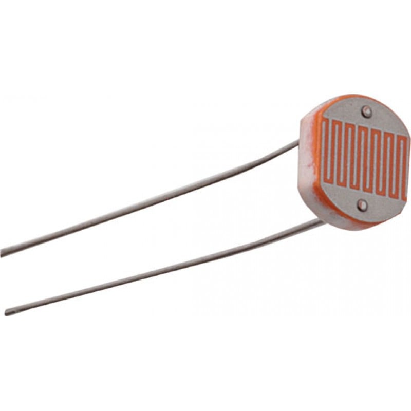
I first decided to test with a Light Dependant Resistor (LDR). An LDR is a component that has a resistance that changes depending on the light intensity that falls on it. That being said I decided to use it to sense the light (DUH!) and turn on an LED when it's dark, kinda like a night light.
The LDR gives out an analog voltage when connected to VCC (5V), the analog voltages changes depending on the intensity of light around the LDR. Higher light intensity means greater voltage from the LDR.
This means that I need to connect the LDR to an Analog Pin, the atmega328-P has a built in ADC (Analog to digital converter) that convers the voltage range of (0-5)V to (0-1023).
I tested the LDR first and figured out that when it's dark the reading is below 300.
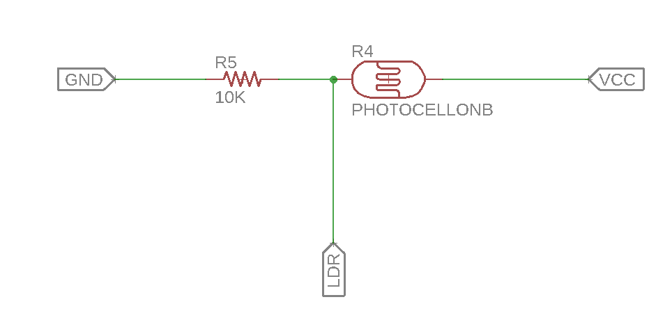
I connected the LDR to Analog pin 0 in the Nadino Board, and connected a resistance of 10K Ohm that acts as a voltage divider and then blinked in LED in the board which is connected to pin 5.
The schematic of the connection is seen below.
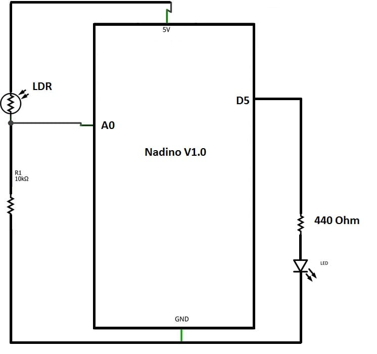
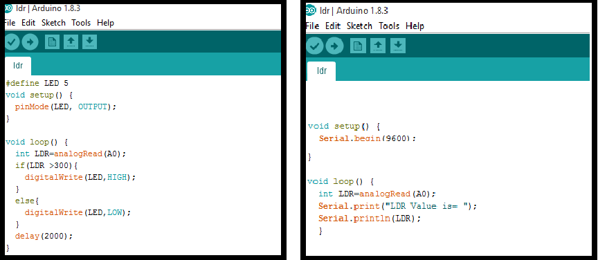
Then I wrote the code using the Arduino IDE. It's pretty simple, it reads the value from the LDR and if it's below 300 it lights up the LED.
Why 300?
I tested the LDR by reading and printing the values it reads and I noticed when I cover the LDR the values are always below 300.
The below video shows how it works.
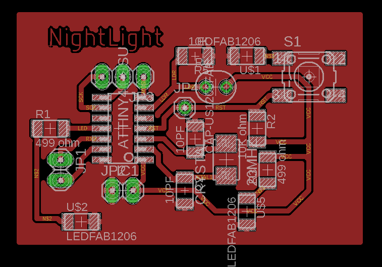
Designing a NightLight Board
I wanted to design a board that would automatically turn an LED on when it detects darkness. Basically what's on the breadboard on a separate PCB.
The schematics are seen below.
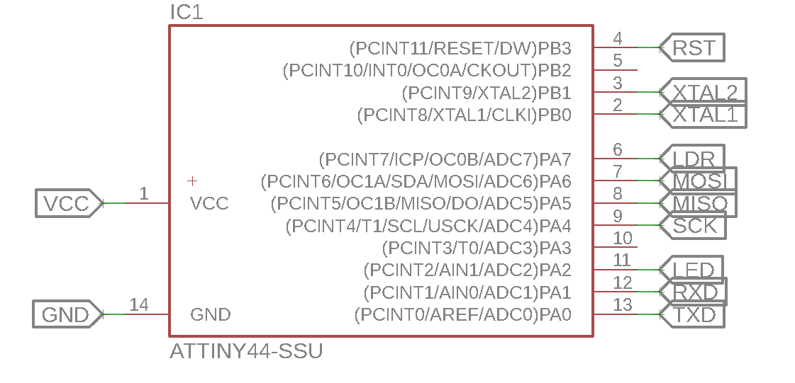
I decided to use Attiny44 since it's only going to have an LDR and an LED. The LDR is connected to PA7 which corresponds to Analog pin 7 on the arduino and the LED is connected to PA2 which corresponds to pin 2 on the Arduino.
The rest of the schematic is basically the same as the EchoHello board.
The schematic for how the LDR is connected is seen below, I basically took what's on the breadboard and put it on a PCB.
The board turned out to be really small arond 4x3 cm and I didn't really face any problems with routing.
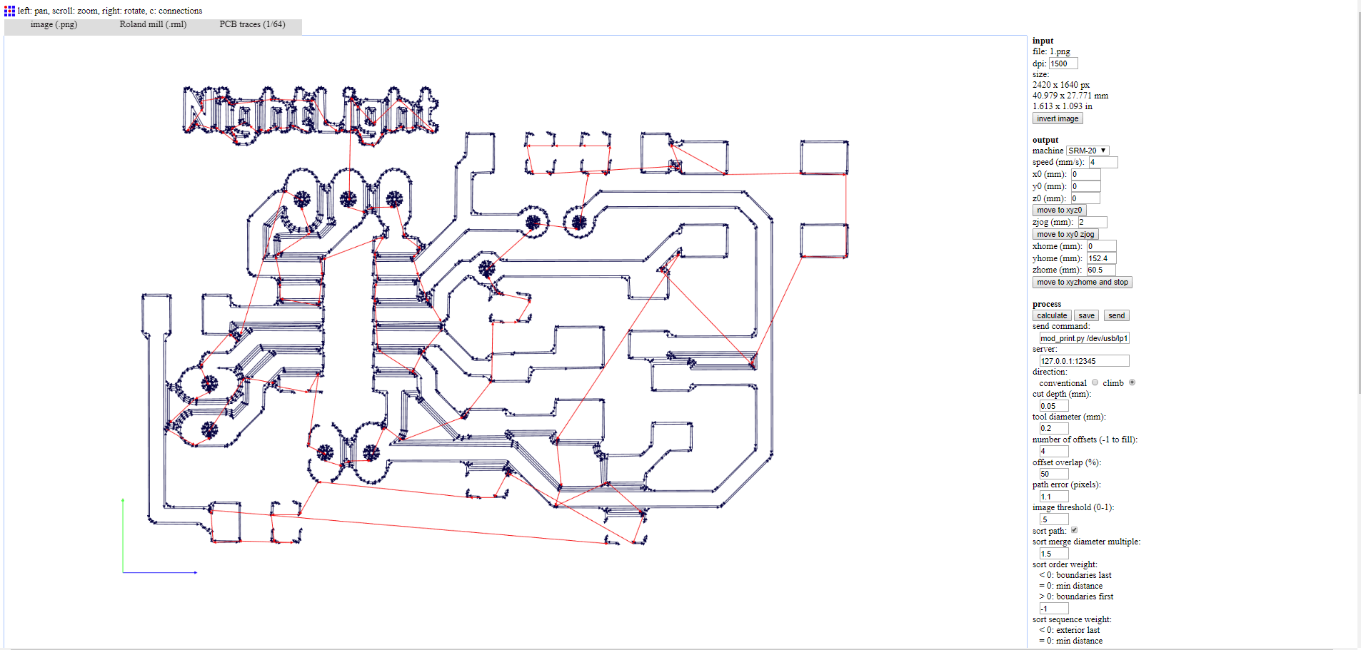
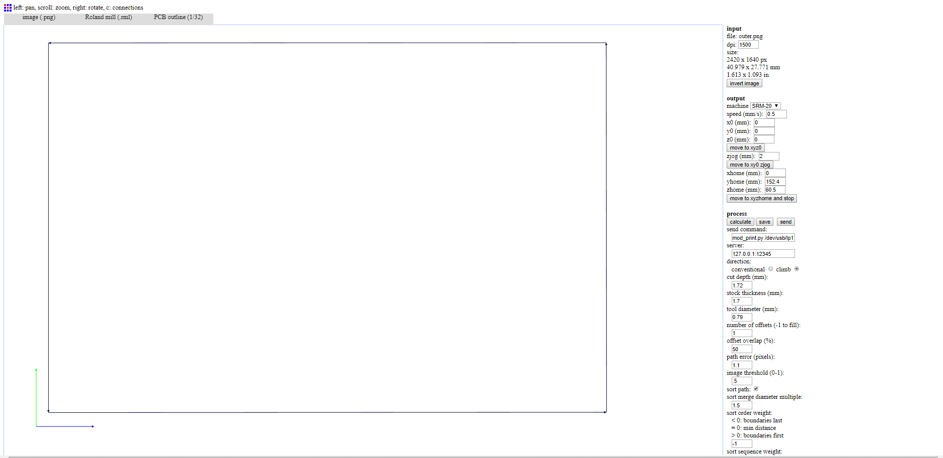
Next, I imported the board displaying only the top layer and the pads as an monochrome image and used Fabmodules to set the settings of milling as seen below.
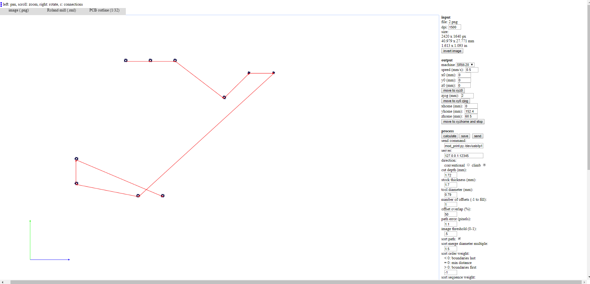
The settings for the drills and outcut is seen below.
Sodlering the board was pretty easy as it didn't have a lot of component.
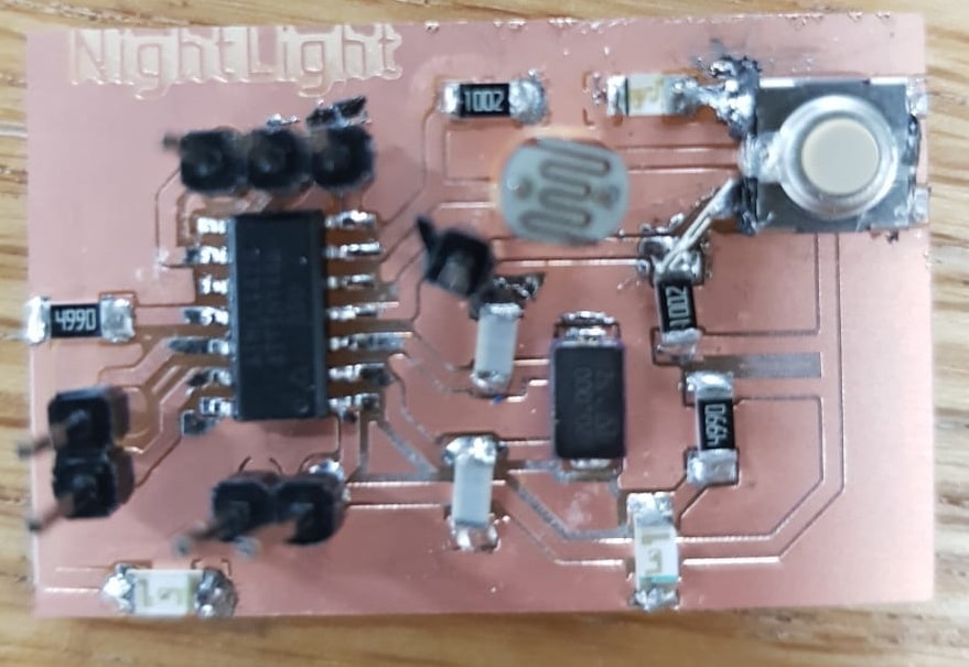
The below video shows what happens when I cover the LDR with my finger lighting an LED. I used the same code as before and programmed it using Arduino as an ISP.
Ultrasonic Sensor
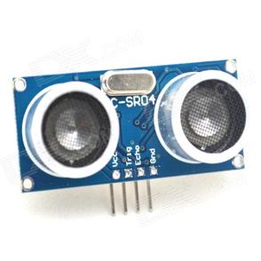
The Ultrasonic Sensor sends out a high-frequency sound pulse and then times how long it takes for the echo of the sound to reflect back. The sensor has 2 openings on its front. One opening transmits ultrasonic waves, (like a tiny speaker, called the trigger), the other receives them, (like a tiny microphone, called the echo).
The speed of sound is approximately 341 meters per second in air. The ultrasonic sensor uses this information along with the time difference between sending and receiving the sound pulse to determine the distance to an object. It uses the following mathematical equation:
Distance = Time x (Speed of Sound)/2
Time = the time between when an ultrasonic wave is transmitted and when it is received
You divide this number by 2 because the sound wave has to travel to the object and back.
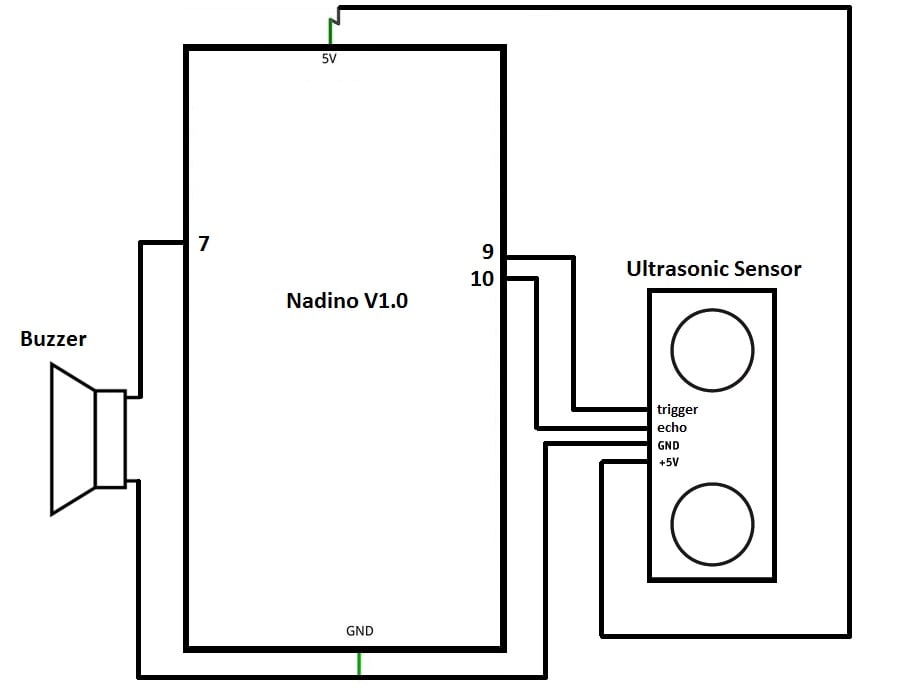
I decided to create a sort of ultrasonic bell, where a buzzer would ring if anything comes within half a meter of the sensor.
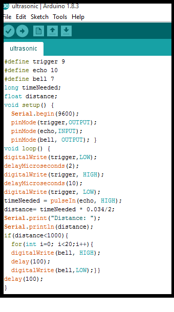
To do that, I connected the trigger pin of the Ultrasonic sensor to pin 9 on my Nadino board and connected the echo pin to pin 10 on the nadino and connected the buzzer to pin 7. As seen below.
The code is pretty simple, if the measured distance is less than 1 meter, the bell will ring.
I used a function in Arduino called the pulseIn, this function reads a pulse (either HIGH or LOW) on a pin. For example, if value is HIGH, pulseIn() waits for the pin to go HIGH, starts timing, then waits for the pin to go LOW and stops timing. Returns the length of the pulse in microseconds .
I used this on the echo pin to measure the time it took the echo of sound to reflect back.
I also wanted to see if it works right so I took the below video of me entering the space where the sensor is placed.
Temperature Sensor
I also tested out a temperature sensor (thermocouple). The thermocouple is a K type thermocouple and it has to be connected to a converter that will digitze the reading and that's where the MAX6675 Module comes in. This module makes it easy for us to read the thermocouple's signal and process it using the Nadino.
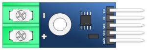
The MAX6675 has the following pins:
- SO: The module's serial output.
- CS: Chip Select. Setting low, selects the Module and tells it to supply an output that is synchronize with a clock.
- SCK : The Serial Clock.
- VCC: 5V supply.
- GND: Ground.
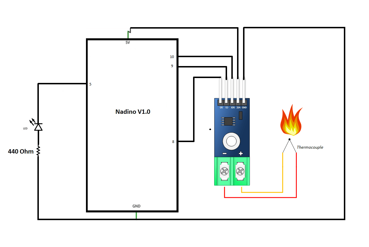
I connected the thermocouple to the MAX6675 module and the module to my Nadino as seen in the below schematics.
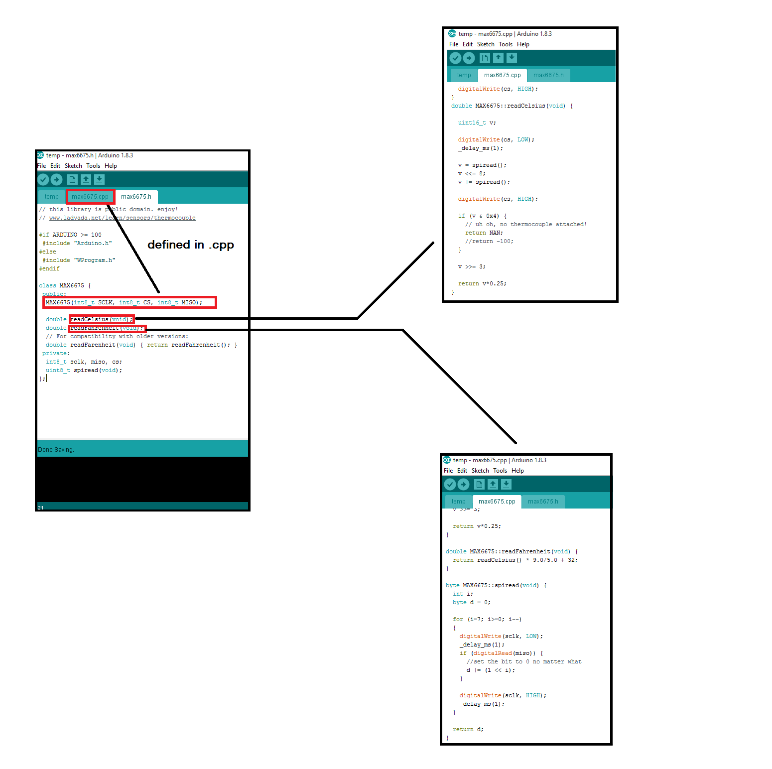
Coding this wasn't as simple as the previous sensors as it involved including a library.
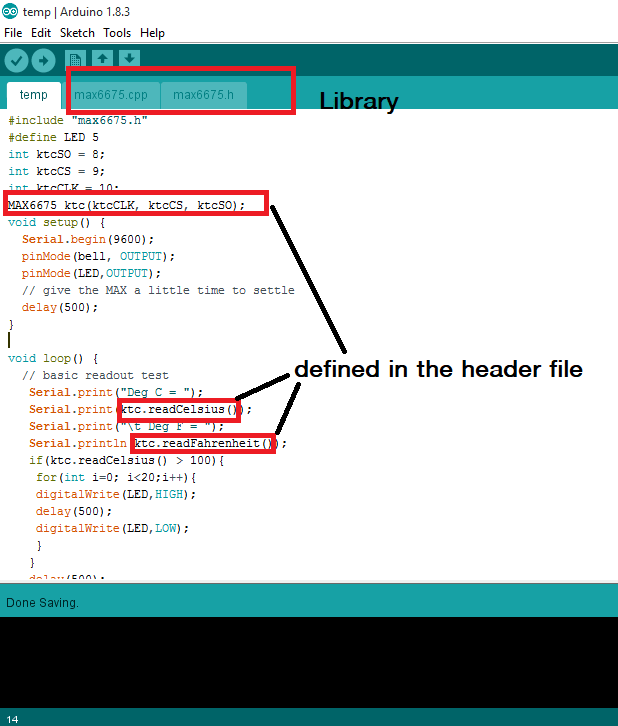
I wrote a code that will light up an LED when the temperature reads above 100 degrees Celsius as seen in the below video.
Here's me trying not to burn the lab down (just kidding).
Problems?
The only problem I faced this week was with the LDR, as seen in the above schematics, one pin of the LDR is supposed to be connected to the Analog Input and the other to 5V, I accidentally connected it to GND instead and the readings were pretty messed up. Luckily I reviewed the connection and figured out the error.
You can download my files here.
