Computer-Aided Design Week
This week we learnt Computer Aided Design. Our assignment was to model something related to our final project.
We had a lot of software options, I knew a little bit of CAD using autocad and sketchup but I wanted to learn new softwares to use.
I first started with  Fusion 360, turning my hand sketch shown below into a cad design.
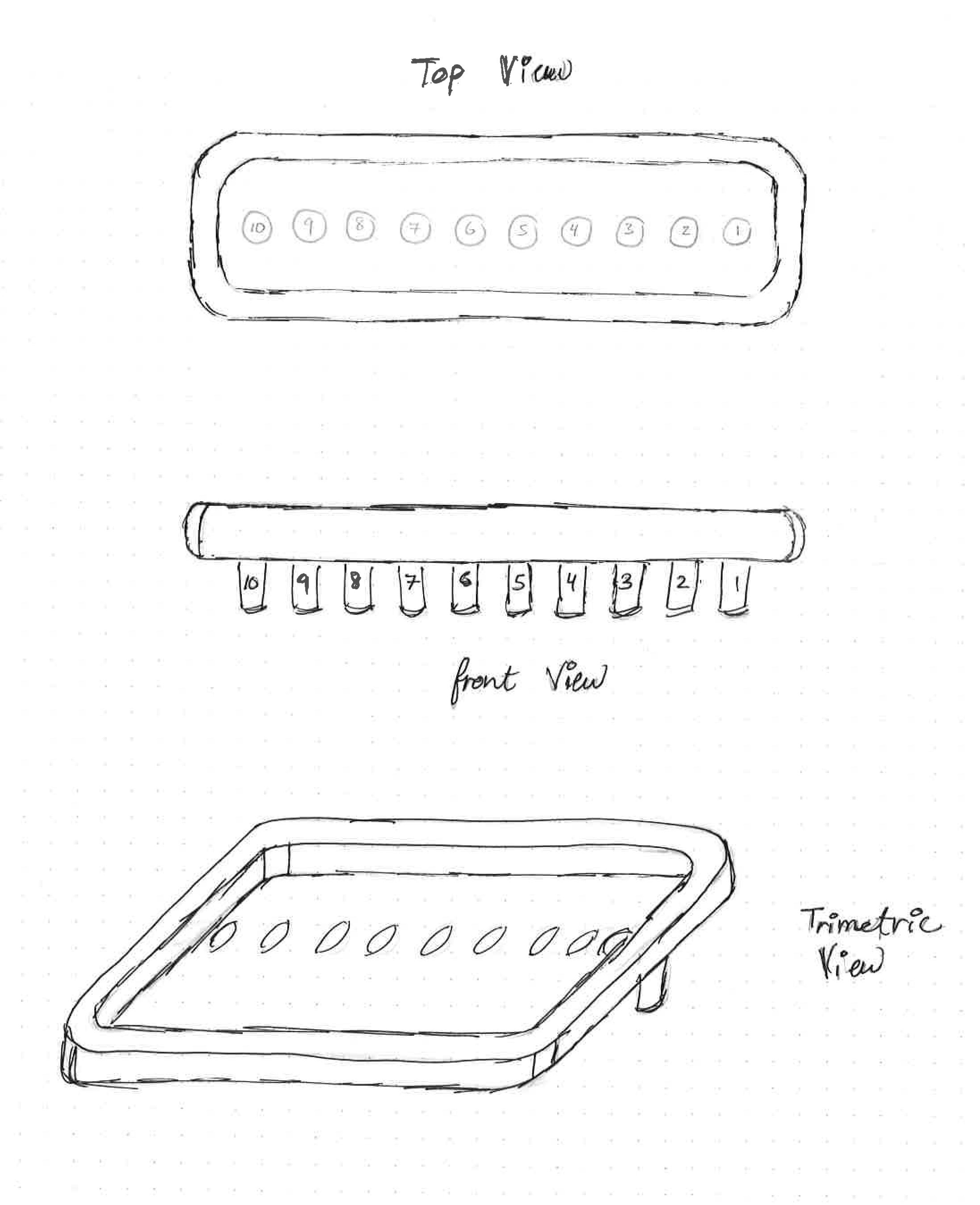
I wanted to design the water tank that will have the solenoid valves connected through it to control the water flow.
To sketch something you either sketch on a plane, or a face.
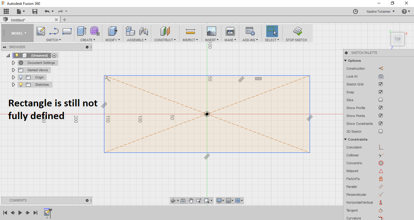
I started with the top plane, sketching a rectangle. When your sketch is colored in blue it means that it is still not fully-defined, as seen below.
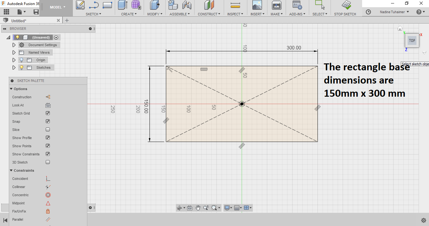
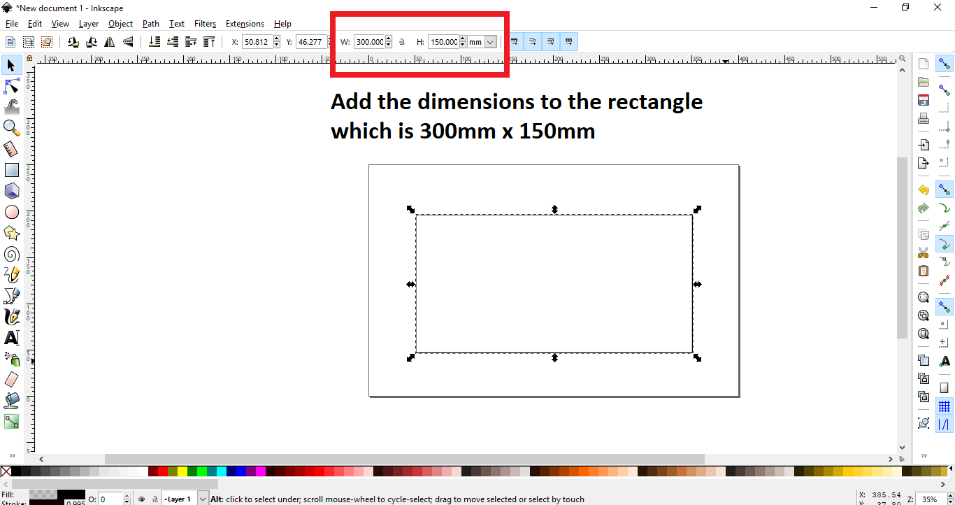
To fully define a sketch, I chose the center rectangle and placed it in the origin and then added dimensions, I then noticed the sketch was colored in black which means it is fully-defined as seen below. The dimensions are 300mm x 150mm.
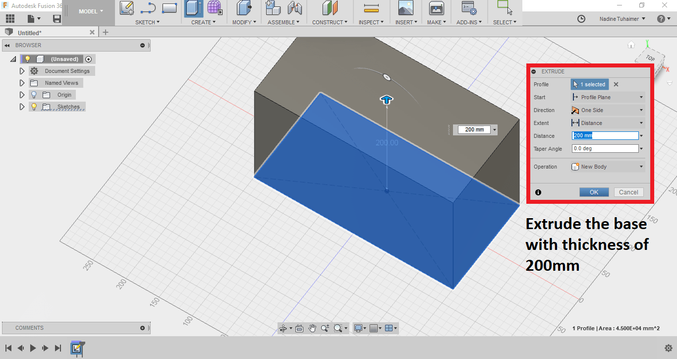
I then extruded the 2D rectangle into a 3D object with press pull. I added the dimension of the thickness I wanted, which was 200mm as seen below.
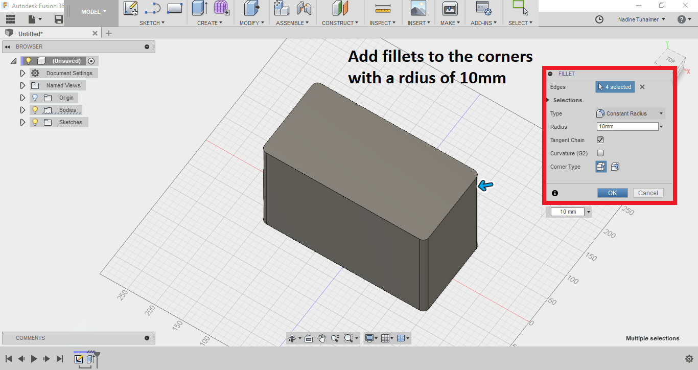
Then I added fillets to the corners of the cuboid. The radius I chose was 10mm.
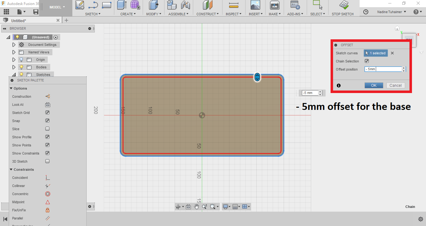
Then I used offset on the top of the cuboid to press pull it to the bottom to create the water tank. I chosea -5mm offset, the minus means it will be less than the original dimension.
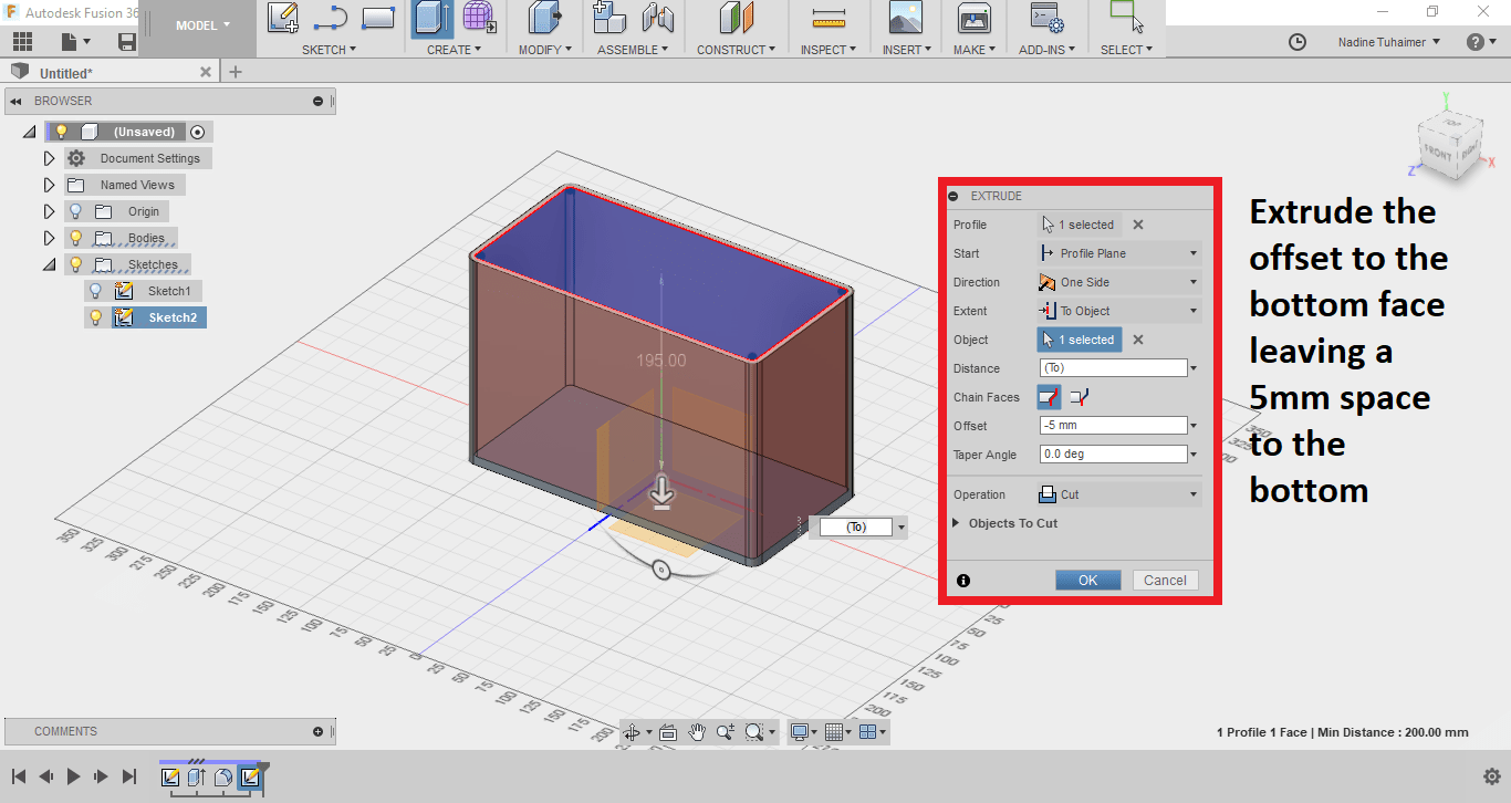
To extrude it, I used press pull but this time I changed the settings to "To Object" and choose the bottom face of the cuboid with an offset of "-5" which means it'll stop "5mm" before the bottom face subtracting material instead of adding.
Then I wanted to add the cylinders to the bottom of the cuboid I created so I switched to the bottom view, using the right-click of the mouse on the bottom face I chose sketch to begin another sketch.
I added construction lines to sketch accurately.
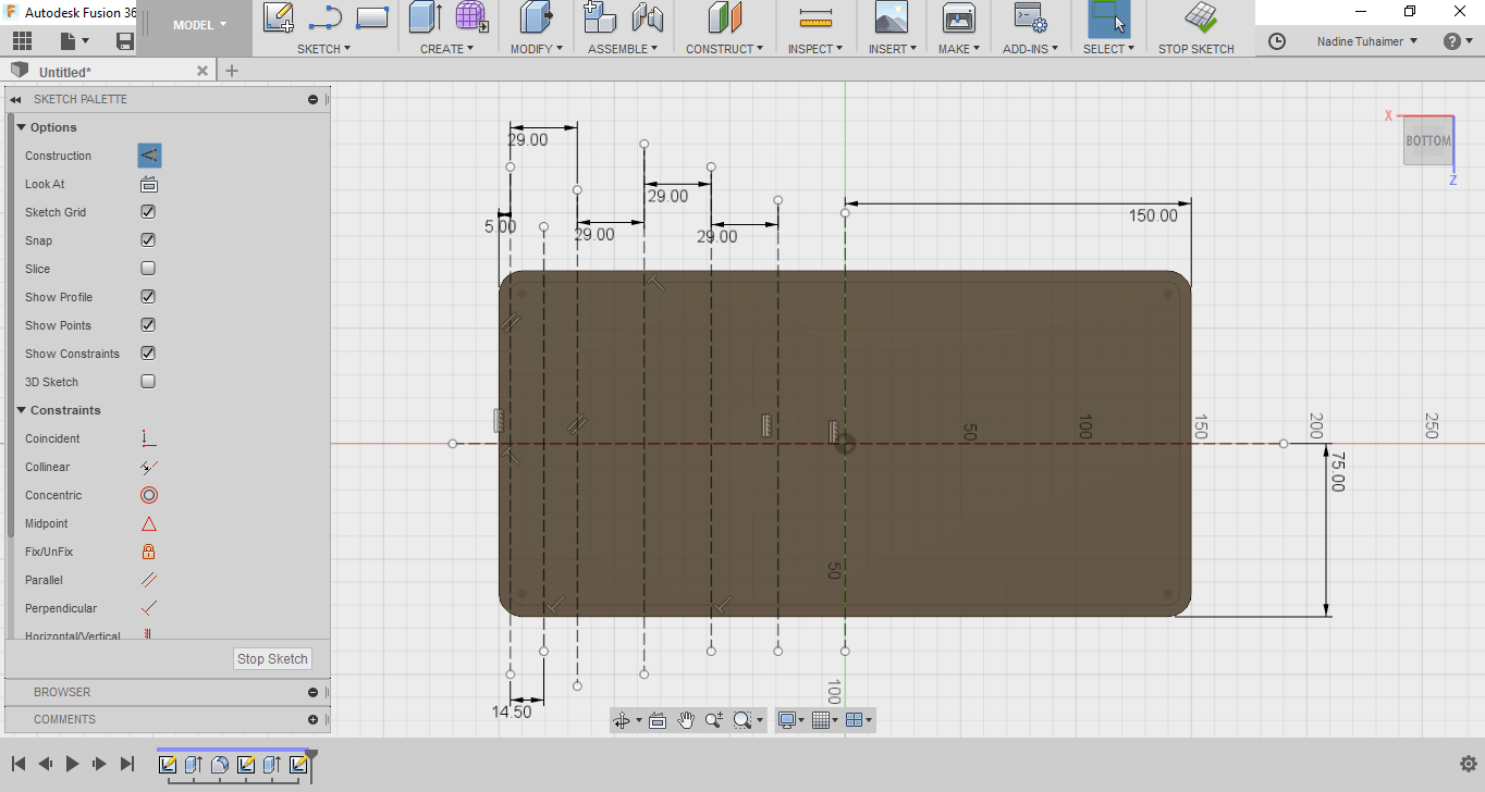
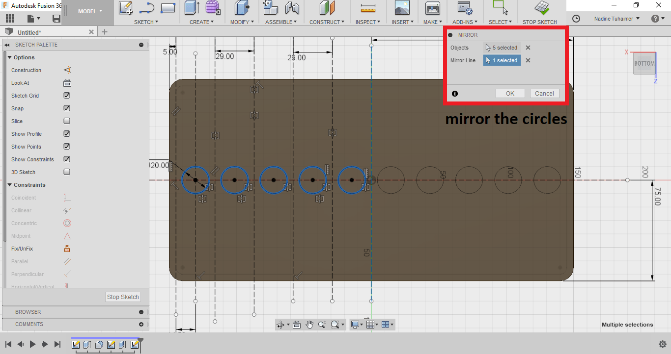
Then I started drawing the base of the first cylinder with a circle with the diameter of 20mm, I fully defined the circle by adding the diameter then I mirrored it to have the rest of the circles follow its parametric properties. This way if I change the dimension of one circle the rest of the circles will change as well.
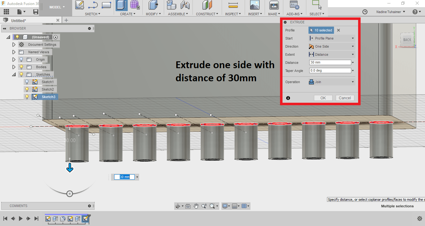
Then I extruded the circles into cylinders by selecting all 10 circles and press pulling them together. This way I can edit the length of all of the cylinders by editing only one feature. The length I chose was 30mm.
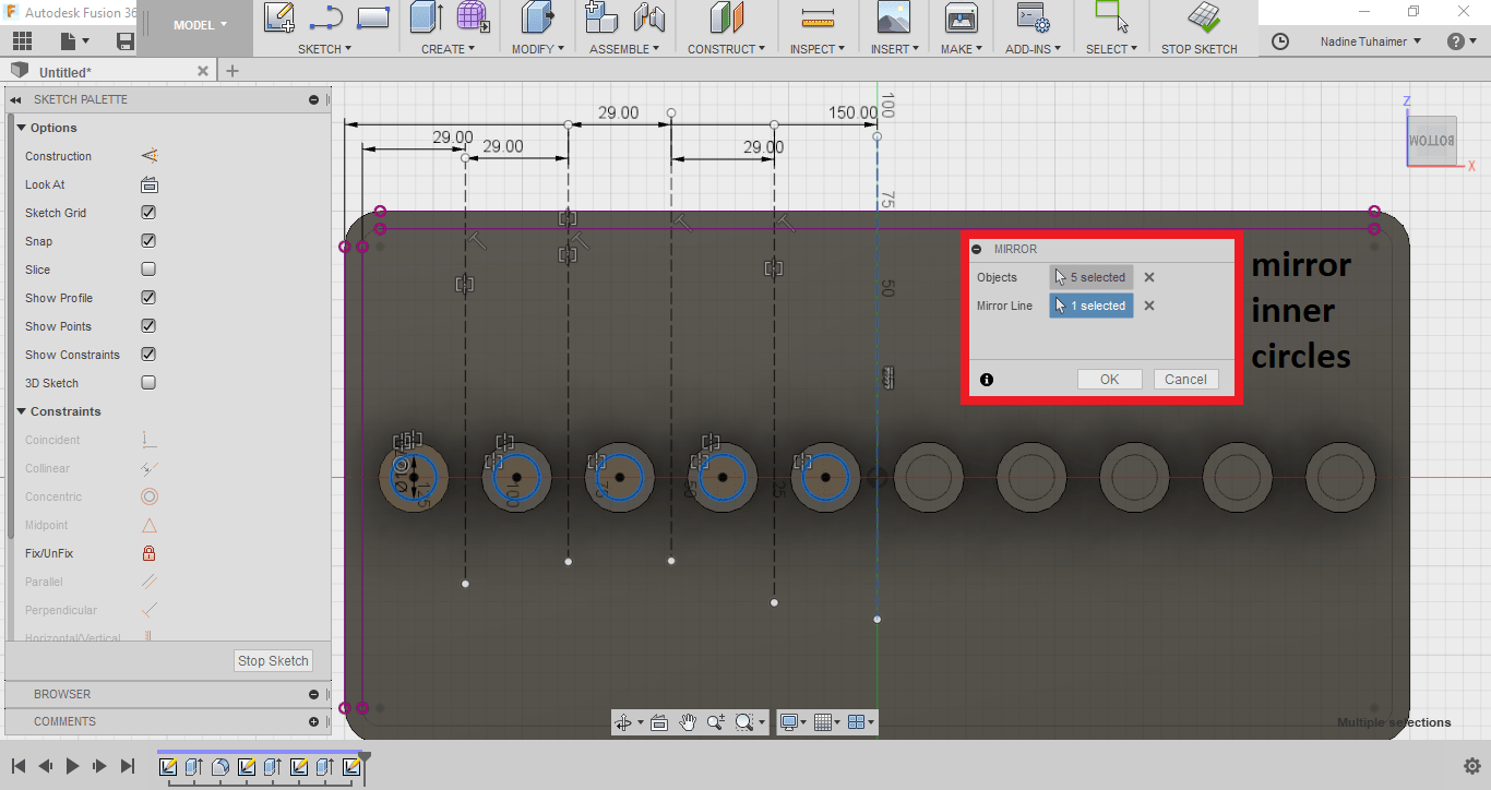
Then I sketched the inner circle and mirrored it as well, after I did that, I figured it would have probably been easier if I just used offset (future note to self, remember offset!).
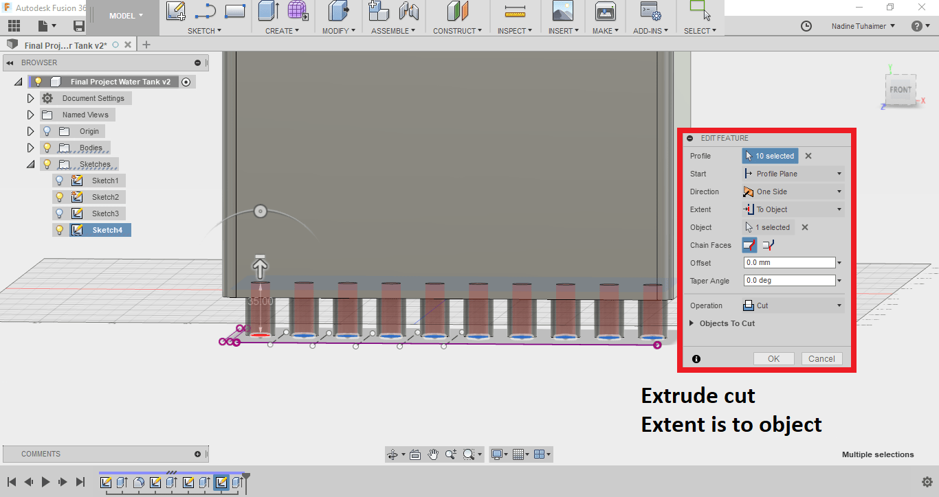
Then I used press pull but this time, I chose the option "To Object" and choose the inner rectangular base. This way the cylinder will cut through creating the pipe that water will flow through to the solenoid valve.
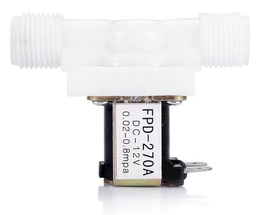
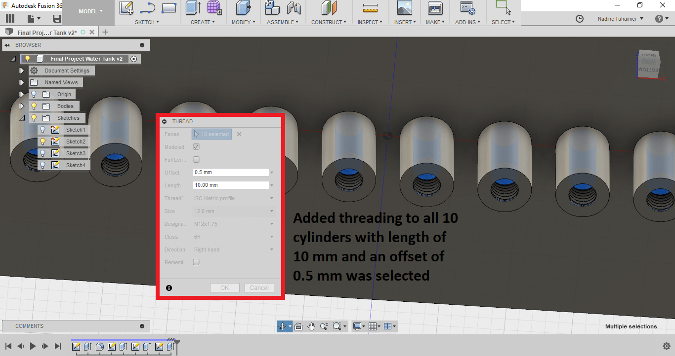
Then I wanted to add threads, so I'll just screw the solenoid valve to the water tank. I selected all 10 cylinders and threaded them together as seen below. The valve I'll be using is also present for reference.
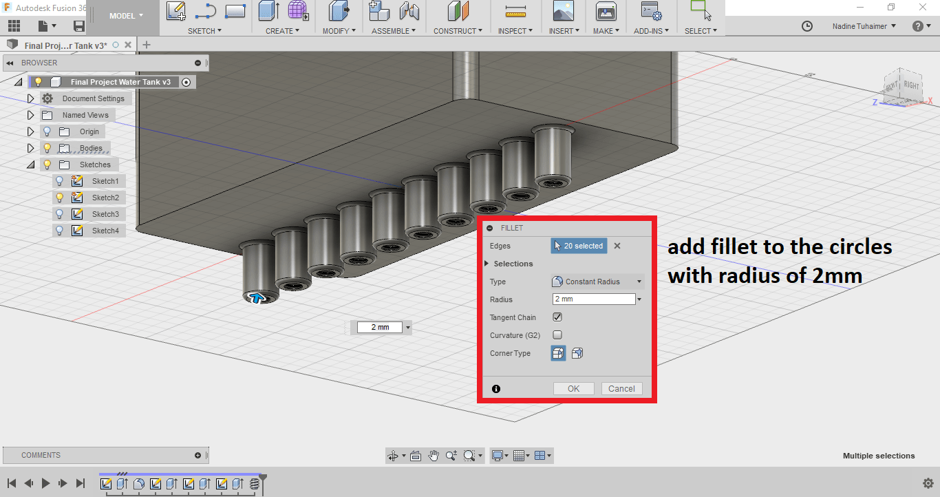
Then I added a fillet to the cylinders just to make it pretty as seen below.
You can see my design in 3D here.
Next I wanted to design the 3D Printed perforated base that the water will pass through to be pumped again to the top but then I realized it doesn't have to be 3D Printed, it can simply be a lasercut acrylic sheet which means I need to design it in 2D.
For that I chose to use,  InkScape. To learn the basics, I watched a couple of youtube tutorials.
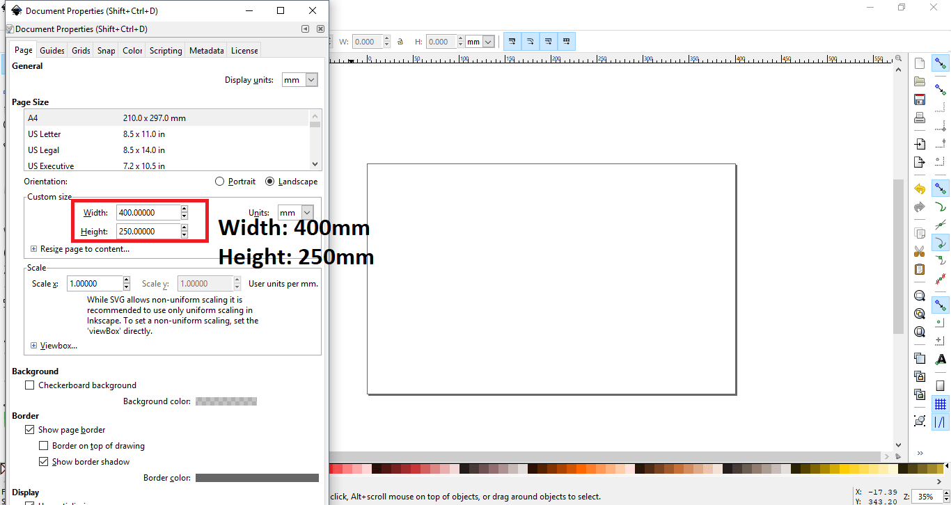
The first thing I did was change the canvas dimensions from document properties. I wanted to sketch something that was 300mm x 150mm so I made the canvas a little bit larger as seen below.
Then I drew the acrylic base that I will be cutting by drawing a rectangle and set the dimensions as shown below.
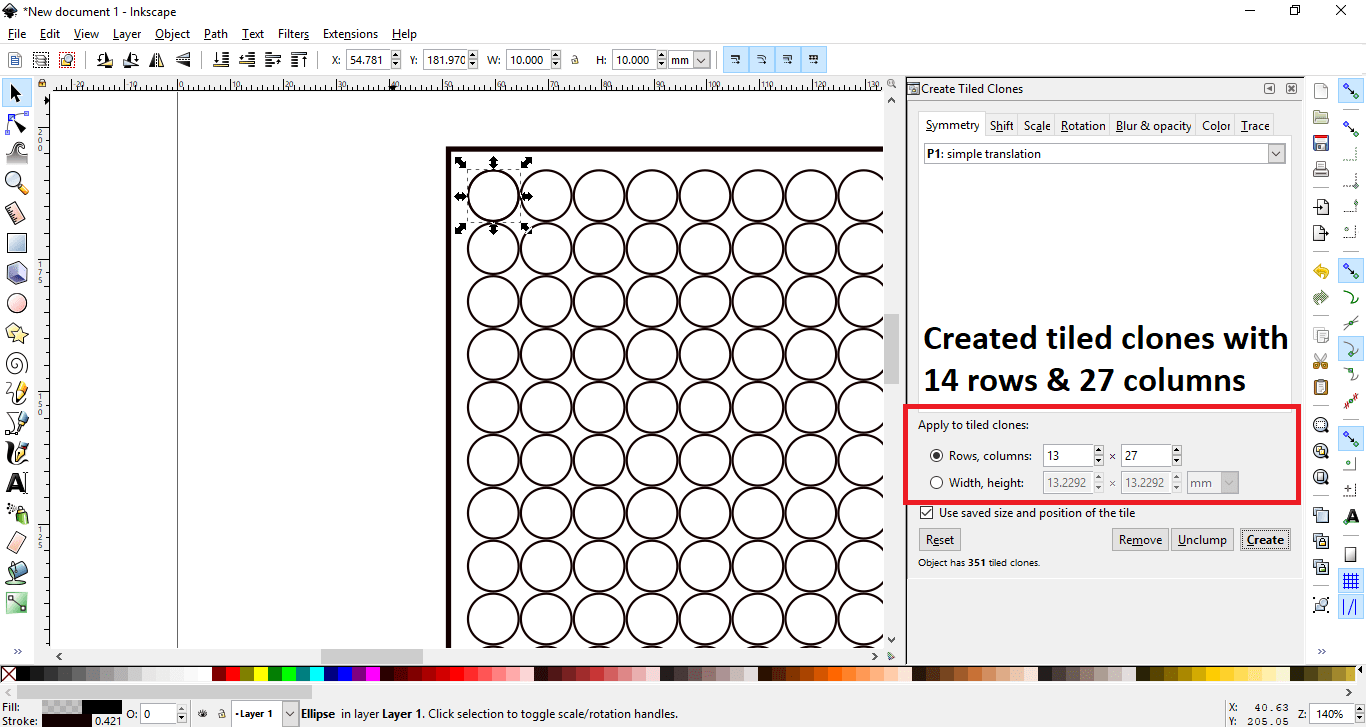
After that I drew the first circle that will be cut. Then instead of drawing each circle separately, I decided to create a tiled clone as seen below.
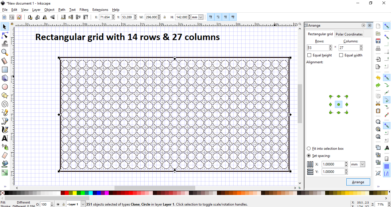
Then I arranged it giving a 1mm space in the x-axis and the y-axis as seen below.
Next I wanted to design a stepper motor holder for an internal project at work. I decided to use another software just to familiarize myself with more design softwares. I chose to use  Solidworks.
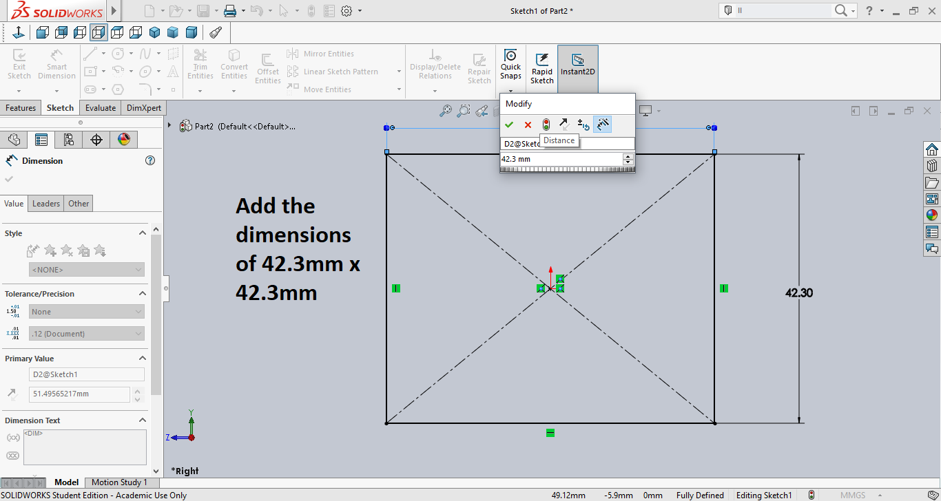
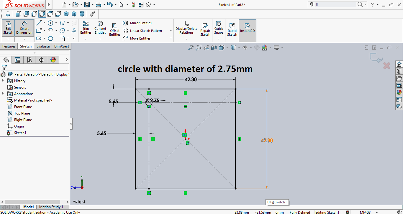
I chose the right plane to draw on. and I drew a center rectangle at the origin. At first it was colored in blue, which means it's still not fully defined, so I used smart dimensions to add the dimensions to it, which are 42.3mm x 42.3mm. Then it turned to black as seen below.
Next I wanted to add the holes for the screws. To do that I drew 2 lines for construction, then I drew a center circle with a diameter of 2.75mm as seen below.
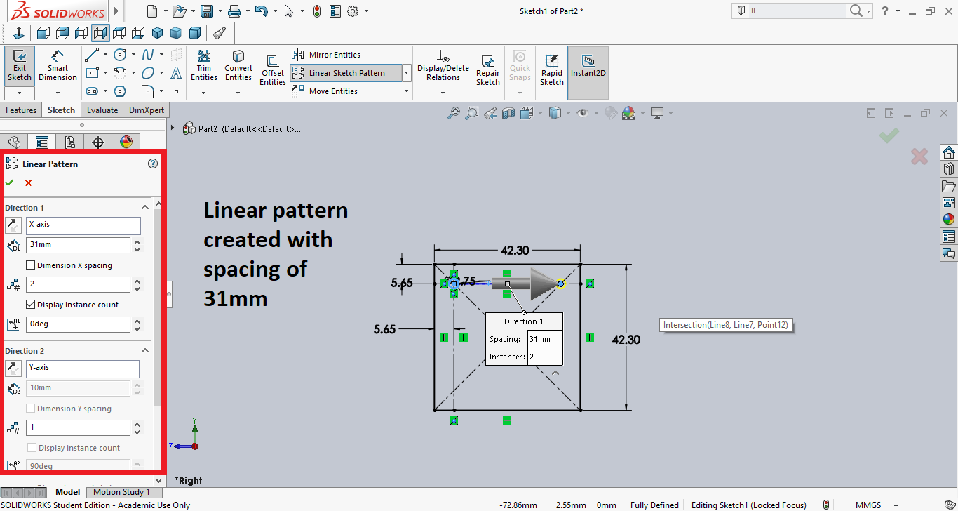
Then instead of drawing the 3 other holes from scratch, I created a linear pattern to the right as seen below.
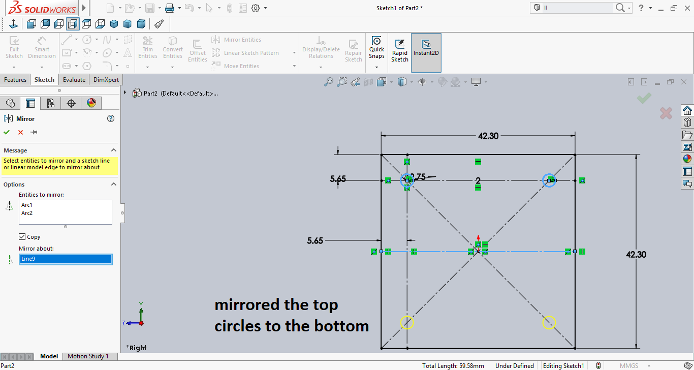
Then I used mirroring to create the bottom holes as seen below.
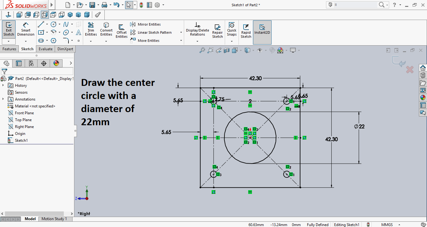
Then I created the center circle as seen below.
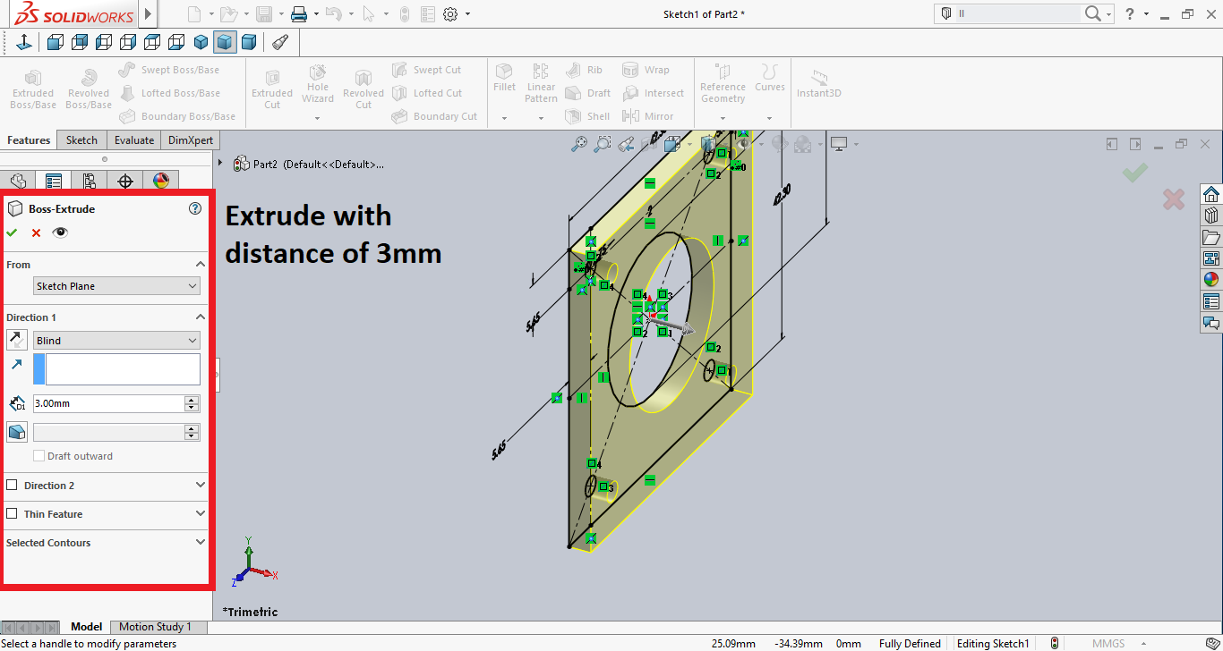
Then I used extrude and gave it a thickness of 3mm as seen in the below image.
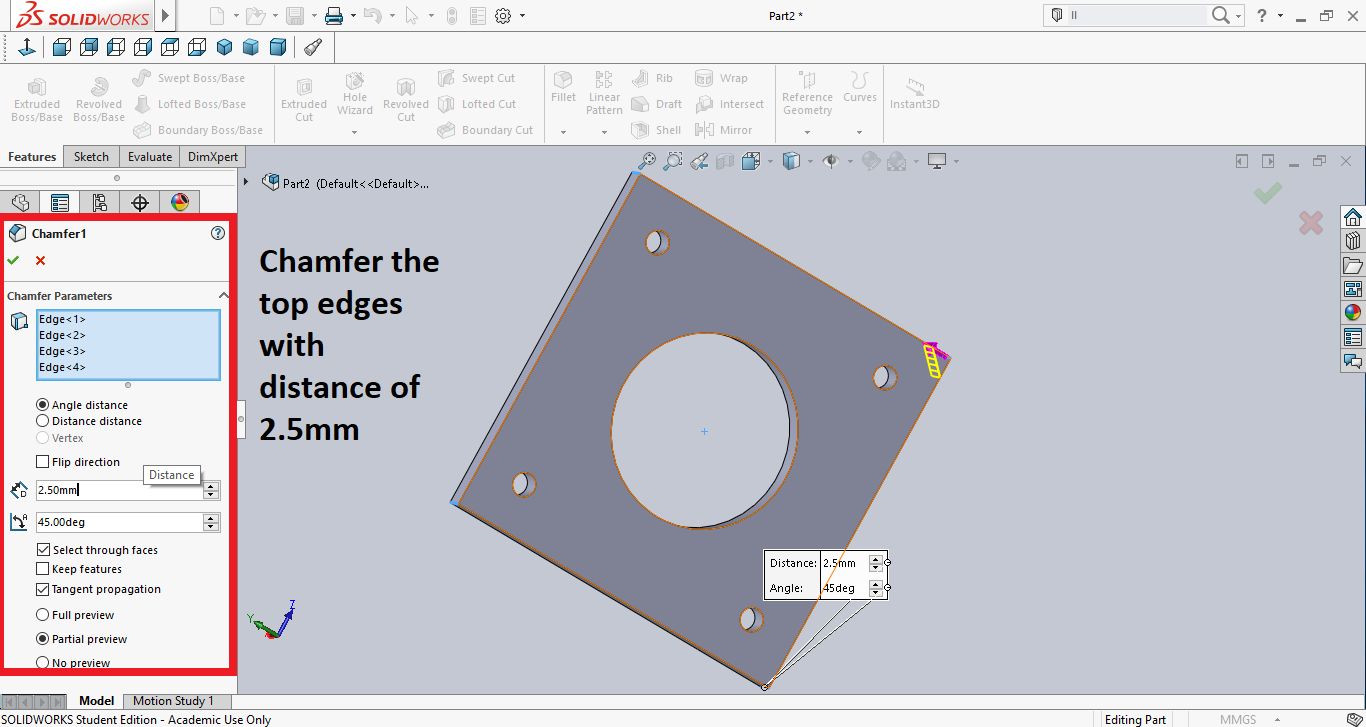
Then I used chamfer to cut the edges. But only the top ones as the bottom will have a base to carry the stepper motor.
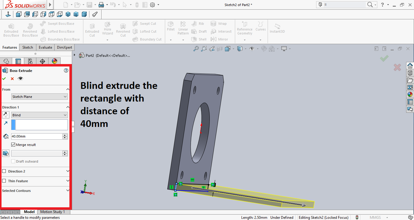
Then I sketched a rectangle and extruded it to create the base as seen below.
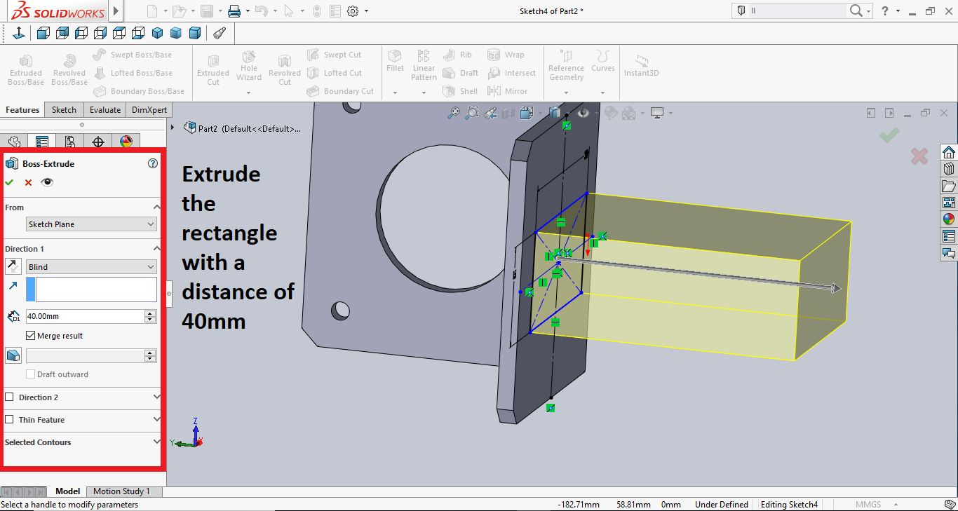
Then I switched to the bottom and sketched a rectangle then extruded it to create the holder.
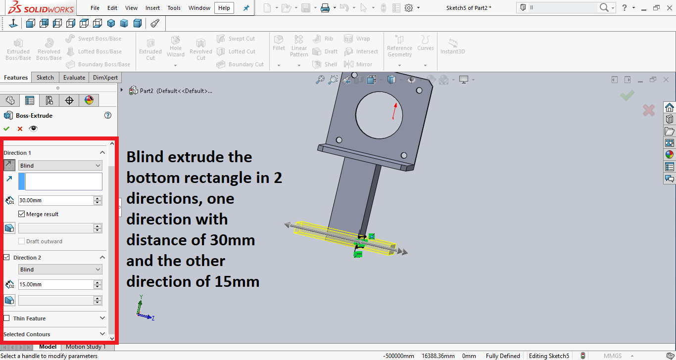
Then I drew another rectangle on the bottom of the holder I extruded in the previous step and extruded in 2 directions. This will have the holes for screws.
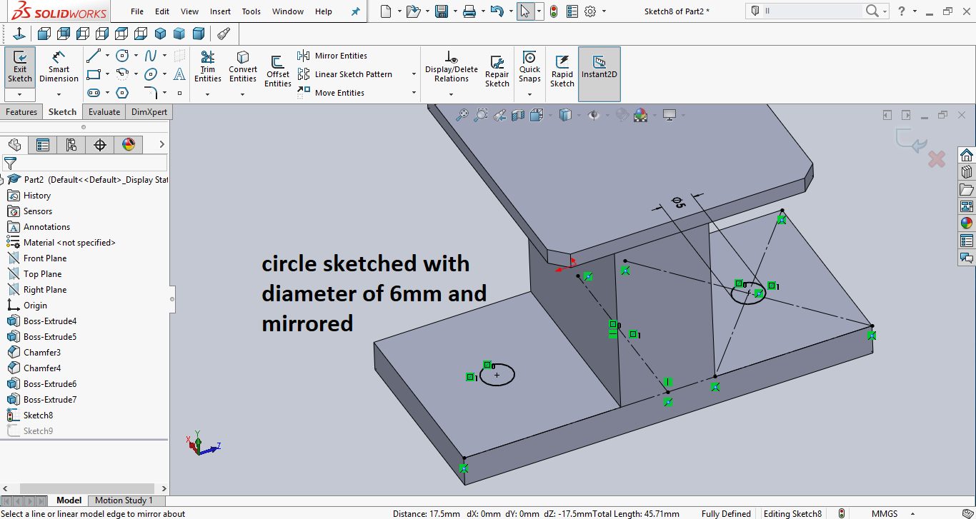
Then on the bottom, I drew a circle and mirrored it to the other side. The diameter is 6mm.
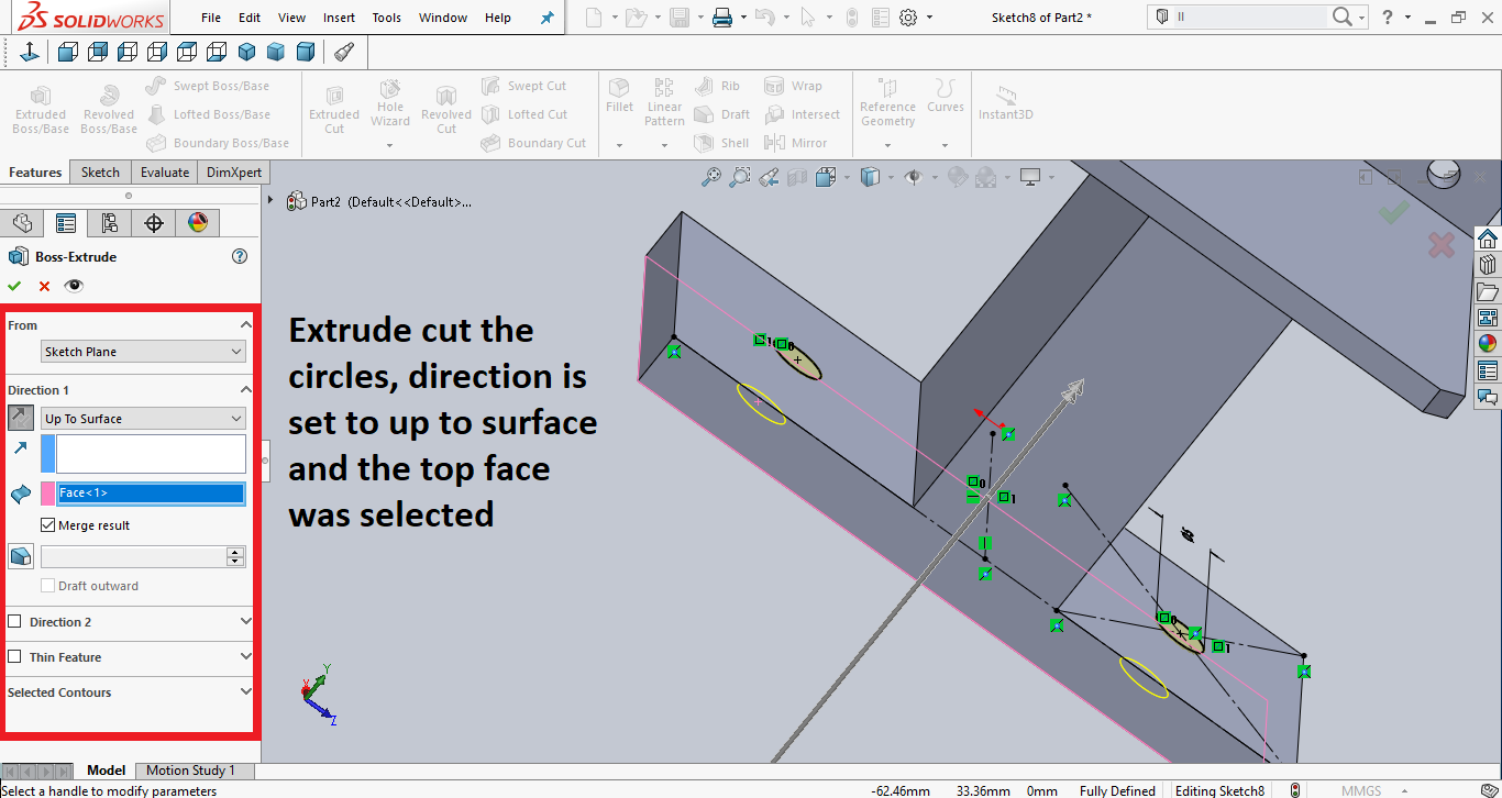
Then I selected the two circles to extrude but this time I chose to surface and selected the top surface.
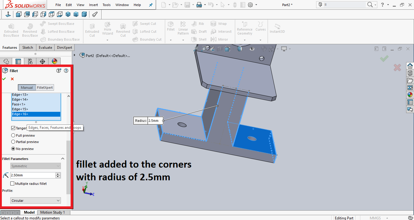
Then I selected the edges to create a fillet because circular edges are prettier in my opinion.
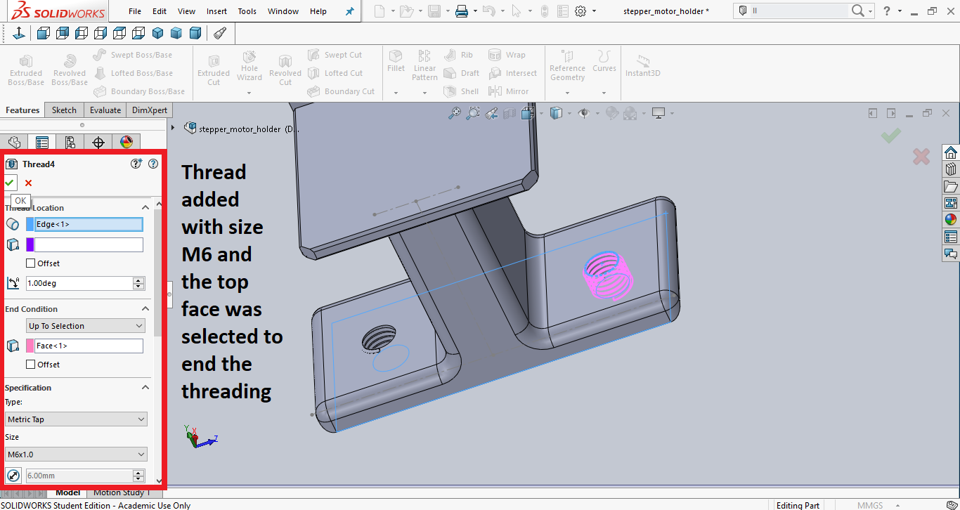
Then I added threads to the holes by choosing threads, I chose the M6 and the condition to stop the threading at up to selection and selected the bottom face of the holder.
You can check out my design here.
You can download my designs here:
